EP0917004A2 - Système de dispositifs porte-objet et appareil d'exposition avec un tel système - Google Patents
Système de dispositifs porte-objet et appareil d'exposition avec un tel système Download PDFInfo
- Publication number
- EP0917004A2 EP0917004A2 EP98309167A EP98309167A EP0917004A2 EP 0917004 A2 EP0917004 A2 EP 0917004A2 EP 98309167 A EP98309167 A EP 98309167A EP 98309167 A EP98309167 A EP 98309167A EP 0917004 A2 EP0917004 A2 EP 0917004A2
- Authority
- EP
- European Patent Office
- Prior art keywords
- stage
- countermass
- vertical direction
- pulley
- connecting members
- Prior art date
- Legal status (The legal status is an assumption and is not a legal conclusion. Google has not performed a legal analysis and makes no representation as to the accuracy of the status listed.)
- Withdrawn
Links
Images


Classifications
-
- H—ELECTRICITY
- H01—ELECTRIC ELEMENTS
- H01L—SEMICONDUCTOR DEVICES NOT COVERED BY CLASS H10
- H01L21/00—Processes or apparatus adapted for the manufacture or treatment of semiconductor or solid state devices or of parts thereof
- H01L21/02—Manufacture or treatment of semiconductor devices or of parts thereof
- H01L21/027—Making masks on semiconductor bodies for further photolithographic processing not provided for in group H01L21/18 or H01L21/34
-
- G—PHYSICS
- G03—PHOTOGRAPHY; CINEMATOGRAPHY; ANALOGOUS TECHNIQUES USING WAVES OTHER THAN OPTICAL WAVES; ELECTROGRAPHY; HOLOGRAPHY
- G03F—PHOTOMECHANICAL PRODUCTION OF TEXTURED OR PATTERNED SURFACES, e.g. FOR PRINTING, FOR PROCESSING OF SEMICONDUCTOR DEVICES; MATERIALS THEREFOR; ORIGINALS THEREFOR; APPARATUS SPECIALLY ADAPTED THEREFOR
- G03F7/00—Photomechanical, e.g. photolithographic, production of textured or patterned surfaces, e.g. printing surfaces; Materials therefor, e.g. comprising photoresists; Apparatus specially adapted therefor
- G03F7/70—Microphotolithographic exposure; Apparatus therefor
- G03F7/70691—Handling of masks or workpieces
- G03F7/70766—Reaction force control means, e.g. countermass
-
- B—PERFORMING OPERATIONS; TRANSPORTING
- B23—MACHINE TOOLS; METAL-WORKING NOT OTHERWISE PROVIDED FOR
- B23Q—DETAILS, COMPONENTS, OR ACCESSORIES FOR MACHINE TOOLS, e.g. ARRANGEMENTS FOR COPYING OR CONTROLLING; MACHINE TOOLS IN GENERAL CHARACTERISED BY THE CONSTRUCTION OF PARTICULAR DETAILS OR COMPONENTS; COMBINATIONS OR ASSOCIATIONS OF METAL-WORKING MACHINES, NOT DIRECTED TO A PARTICULAR RESULT
- B23Q11/00—Accessories fitted to machine tools for keeping tools or parts of the machine in good working condition or for cooling work; Safety devices specially combined with or arranged in, or specially adapted for use in connection with, machine tools
- B23Q11/001—Arrangements compensating weight or flexion on parts of the machine
- B23Q11/0017—Arrangements compensating weight or flexion on parts of the machine compensating the weight of vertically moving elements, e.g. by balancing liftable machine parts
- B23Q11/0025—Arrangements compensating weight or flexion on parts of the machine compensating the weight of vertically moving elements, e.g. by balancing liftable machine parts using resilient means, e.g. springs, hydraulic dampers
-
- B—PERFORMING OPERATIONS; TRANSPORTING
- B23—MACHINE TOOLS; METAL-WORKING NOT OTHERWISE PROVIDED FOR
- B23Q—DETAILS, COMPONENTS, OR ACCESSORIES FOR MACHINE TOOLS, e.g. ARRANGEMENTS FOR COPYING OR CONTROLLING; MACHINE TOOLS IN GENERAL CHARACTERISED BY THE CONSTRUCTION OF PARTICULAR DETAILS OR COMPONENTS; COMBINATIONS OR ASSOCIATIONS OF METAL-WORKING MACHINES, NOT DIRECTED TO A PARTICULAR RESULT
- B23Q11/00—Accessories fitted to machine tools for keeping tools or parts of the machine in good working condition or for cooling work; Safety devices specially combined with or arranged in, or specially adapted for use in connection with, machine tools
- B23Q11/001—Arrangements compensating weight or flexion on parts of the machine
- B23Q11/0028—Arrangements compensating weight or flexion on parts of the machine by actively reacting to a change of the configuration of the machine
-
- B—PERFORMING OPERATIONS; TRANSPORTING
- B23—MACHINE TOOLS; METAL-WORKING NOT OTHERWISE PROVIDED FOR
- B23Q—DETAILS, COMPONENTS, OR ACCESSORIES FOR MACHINE TOOLS, e.g. ARRANGEMENTS FOR COPYING OR CONTROLLING; MACHINE TOOLS IN GENERAL CHARACTERISED BY THE CONSTRUCTION OF PARTICULAR DETAILS OR COMPONENTS; COMBINATIONS OR ASSOCIATIONS OF METAL-WORKING MACHINES, NOT DIRECTED TO A PARTICULAR RESULT
- B23Q5/00—Driving or feeding mechanisms; Control arrangements therefor
- B23Q5/22—Feeding members carrying tools or work
- B23Q5/28—Electric drives
-
- G—PHYSICS
- G03—PHOTOGRAPHY; CINEMATOGRAPHY; ANALOGOUS TECHNIQUES USING WAVES OTHER THAN OPTICAL WAVES; ELECTROGRAPHY; HOLOGRAPHY
- G03F—PHOTOMECHANICAL PRODUCTION OF TEXTURED OR PATTERNED SURFACES, e.g. FOR PRINTING, FOR PROCESSING OF SEMICONDUCTOR DEVICES; MATERIALS THEREFOR; ORIGINALS THEREFOR; APPARATUS SPECIALLY ADAPTED THEREFOR
- G03F7/00—Photomechanical, e.g. photolithographic, production of textured or patterned surfaces, e.g. printing surfaces; Materials therefor, e.g. comprising photoresists; Apparatus specially adapted therefor
- G03F7/70—Microphotolithographic exposure; Apparatus therefor
- G03F7/70691—Handling of masks or workpieces
- G03F7/70716—Stages
-
- G—PHYSICS
- G03—PHOTOGRAPHY; CINEMATOGRAPHY; ANALOGOUS TECHNIQUES USING WAVES OTHER THAN OPTICAL WAVES; ELECTROGRAPHY; HOLOGRAPHY
- G03F—PHOTOMECHANICAL PRODUCTION OF TEXTURED OR PATTERNED SURFACES, e.g. FOR PRINTING, FOR PROCESSING OF SEMICONDUCTOR DEVICES; MATERIALS THEREFOR; ORIGINALS THEREFOR; APPARATUS SPECIALLY ADAPTED THEREFOR
- G03F7/00—Photomechanical, e.g. photolithographic, production of textured or patterned surfaces, e.g. printing surfaces; Materials therefor, e.g. comprising photoresists; Apparatus specially adapted therefor
- G03F7/70—Microphotolithographic exposure; Apparatus therefor
- G03F7/708—Construction of apparatus, e.g. environment aspects, hygiene aspects or materials
- G03F7/70858—Environment aspects, e.g. pressure of beam-path gas, temperature
- G03F7/709—Vibration, e.g. vibration detection, compensation, suppression or isolation
Definitions
- This invention relates to a stage system for use in exposure apparatuses for a lithographic process in manufacture of semiconductor devices, for example, or for use in various precision machining apparatuses or various precision measuring instruments, for example.
- the invention is concerned with an exposure apparatus with such stage system and/or a device manufacturing method using the same.
- a stepper As an exposure apparatus for manufacture of semiconductor devices, for example, there is an apparatus called a stepper.
- a pattern of an original such as a reticle or mask is printed repeatedly on a single substrate such as a wafer while moving stepwise the substrate relative to a projection optical system, for projecting the pattern to the substrate.
- a vertical type stage for holding a substrate such as a wafer in its upstanding position and for moving the substrate stepwise two-dimensionally along a vertical reference plane or a reference plane close to it, is used.
- a countermass mechanism for example, is necessary for the weight compensation of the stage.
- any vibration of such countermass mechanism will cause external disturbance that degrades wafer positioning precision.
- the dynamic characteristic of the stage is deteriorated remarkably.
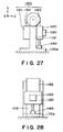
- FIGS 27 and 28 show an example of such vertical type stage.
- This stage comprises an X-Y stage including a Y stage 1120 which is reciprocally movable in Y-axis direction (vertical direction) along a stage base 1110, mounted on a base 1110a, an X stage 1130 which is reciprocally movable in X-axis direction along the Y stage 1120, a cylinder 140 for moving the Y stage 1120 in Y-axis direction, and a linear motor (not shown) for moving the X stage 1130 in X-axis direction.
- the stage base 1110 has a guiding surface for supporting, without contact, the bottom face of the Y stage 1120 through air pads, for example.
- a Y guide (not shown) for guiding the Y stage 1120 in Y-axis direction.
- the Y guide and the Y stage 1120 are kept out of contact with each other, by means of air pads, for example.
- Weight compensation mechanism 1160 serves to cancel the weight of the Y stage 1120, the X stage 1130 and the wafer (not shown) held by it.
- the mechanism comprises a belt 1162 with the Y stage 1120 suspended at one end thereof and with a countermass 1161 suspended at another end thereof.
- the belt extends around and is supported by a pulley 1163.
- the weight of the countermass 1161 is set to be balanced with the weight of stage movable components, including the Y stage 1120, the X stage 1130 and the wafer held thereby.
- the rigidity of the Y guide In order to support such large load, the rigidity of the Y guide has to be enlarged. However, increasing the rigidity of the Y guide necessitates enlargement in size of the Y guide, for example. This results in further enlargement in size and weight of the stage mechanism as a whole, and causes degradation of dynamic characteristic of the stage. Finally, improvement of positioning precision or positioning speed is disturbed.
- a steel belt or wire is used for a belt that connects the stage and the countermass.
- the stage moves, there occurs natural or proper vibration of several ten Hz due to insufficiency of rigidity of the steel belt or the like.
- a natural vibration of not less than 50 Hz, for example, of the countermass itself is propagated through the belt to the stage.
- a stage system comprising: a first stage movable along a reference plane, containing a vertical direction, and in the vertical direction or in a first direction close to the vertical direction; a second stage movable in a second direction intersecting with the first direction and relative to the first stage; a first driving mechanism for moving the first stage in the first direction; a second driving mechanism for moving the second stage in the second direction; a countermass movable in the first direction; and a third driving mechanism for moving the countermass in a direction opposite to the first direction.
- a stage system comprising: a first stage movable along a reference plane, containing a vertical direction, and in the vertical direction or in a first direction close to the vertical direction; a second stage movable in a second direction intersecting with the first direction and relative to the first stage; a countermass movable in the first direction; a first driving mechanism for moving the first stage in the first direction; and a second driving mechanism for moving the second stage in the second direction; wherein said first driving mechanism includes a magnet and a coil one of which is mounted on one of the first stage and the countermass and the other of which is mounted on the other of the first stage and the countermass, such that the countermass moves in a direction opposite to the first stage.
- a stage system comprising: a stage movable along a reference plane, containing a vertical direction, and in the vertical direction or a direction close to the vertical direction; a countermass, balancing with a weight of the stage; connecting members for connecting the countermass to the stage; a pulley for supporting said connecting members; and an anti-vibration mechanism for reducing vibration to be propagated from said connecting members to the stage.
- a stage system comprising: a stage movable along a reference plane, containing a vertical direction, and in the vertical direction or a first direction close to the vertical direction; connecting members connected to the stage; a pulley for supporting said connecting members; a motor for rotationally driving the pulley and for compensating a weight of the stage; and an anti-vibration mechanism for reducing vibration to be propagated from said connecting members to the stage.
- a stage system comprising: a stage movable along a reference plane, containing a vertical direction, and in the vertical direction or a direction close to the vertical direction; a countermass, balancing with a weight of the stage; connecting members for connecting the countermass to the stage; a pulley for supporting said connecting members; and an actuator for adjusting one of a tension force of and an effective length of the connection members.
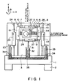
- Figure 1 is a schematic and front view of a vertical type stage system according to a first embodiment of the present invention.
- Figure 2 is a schematic view of a model of a gravity compensation mechanism in the first embodiment of the present invention.
- Figure 3 is a schematic and front view of a vertical type stage according to a second embodiment of the present invention.
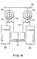
- Figure 4 is a schematic view of a model of a gravity compensation mechanism in the second embodiment of the present invention.
- Figure 5 is a schematic and front view of a vertical type stage system according to a third embodiment of the present invention.
- Figure 6 is a schematic and front view of a vertical type stage system according to a fourth embodiment of the present invention.
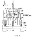
- Figure 7 is a schematic and front view of a vertical type stage system according to a fifth embodiment of the present invention.
- Figure 8 is a schematic and front view of a vertical type stage system according to a sixth embodiment of the present invention.
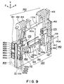
- Figure 9 is a schematic and front view of a stage system according to a seventh embodiment of the present invention.
- Figures 10A and 10B are schematic views, respectively, for explaining a Y guide of Figure 9, wherein Figure 10A is a view for explaining bearing rigidity of the Y guide and Figure 10B shows a section of the Y guide.
- Figure 11 is a schematic view of the stage system of the Figure 9 embodiment, as viewed from the back thereof.
- Figure 12 is a schematic view of a modified form of the Figure 11 embodiment.
- Figure 13 is a schematic view for explaining an example where a bellowphragm is used as an actuator.
- Figure 14 is a schematic view for explaining an example where an air cylinder is used as an actuator.
- Figure 15 is a schematic view for explaining an example where a linear motor is used as an actuator.
- Figure 16 is a schematic view for explaining an example where a laminated rubber member is used in place of an actuator.
- Figure 17 is a block diagram of a control system for an actuator.
- Figure 18 is a block diagram of a control system for a linear motor, for driving a countermass.
- Figure 19 is a graph for explaining frequency characteristic of servo rigidity of a positioning control system.
- Figure 20 is a schematic and perspective view of a stage system an eighth embodiment of the present invention.
- Figure 21 is a schematic view for explaining an actuator of the Figure 20 embodiment.
- Figure 22 is a schematic view for explaining rotary type static bearing used in a bearing portion for a pulley.
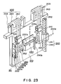
- Figure 23 is a schematic and perspective view of a stage system according to a ninth embodiment of the present invention.
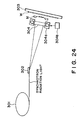
- Figure 24 is a schematic view of a main portion of an X-ray exposure apparatus according to a tenth embodiment of the present invention.
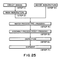
- Figure 25 is a flow chart of semiconductor device manufacturing processes.
- Figure 26 is a flow chart of a wafer process.
- Figures 27 and 28 are schematic views, respectively, of a known vertical type stage system.
- Figure 1 is a schematic and front view of a vertical type stage system according to a first embodiment of the present invention.
- the invention is applied to a vertical type X-Y stage which is incorporated into an X-ray exposure apparatus using synchrotron radiation, for supporting a wafer along a vertical direction and which is movable along the surface of the wafer.
- the X-Y stage system is provided with inertial force applying means and gravity compensating means.
- Denoted in Figure 1 at 1 is a base for supporting the vertical type stage system, and denoted at 2 is an anti-vibration damper for removing or reducing vibration of the base 1.
- Denoted at 3 is a stage base which is supported by the base 1 and which has a reference surface for supporting the stage system.
- Denoted at 4 is a wafer chuck for holding a wafer thereon
- denoted at 5 is a main stage (second stage) for supporting the wafer chuck 4 and being movable along the wafer surface (X-Y plane).
- the main stage 5 has an X measurement mirror 6 and Y measurement mirror 7 fixedly mounted at an end face thereof, for providing reflection surfaces for a position measurement beam.
- Denoted at 8 is a Y stage guide fixedly mounted on the stage base 3, and denoted at 9 is a Y stage base (first stage) being movable in Y direction with the main stage 5 mounted thereon.
- the Y stage guide 8 serves to support the Y stage base 9 with respect to X direction (second direction) and to guide it with respect to Y direction (first direction) without contact thereto.
- Denoted at 10 is an X stage guide fixedly mounted on the Y stage base 9. It serves to support the main stage 5 with respect to Y direction and to guide it with respect to X direction without contact thereto.
- This embodiment uses an air bearing mechanism for non-contact guiding.
- any other mechanism may be used, as long as it can provides a function of low friction guiding.
- Denoted at 51 is a movable element of a linear motor (first driving mechanism) for providing a drive in Y direction. It is fixedly mounted on the Y stage base 9, and is disposed opposed to a linear motor stator (not shown) mounted on the Y stage guide 8.
- the main stage 5 is provided with a movable element (not shown) of another linear motor (second driving mechanism) for providing a drive in X direction. It is disposed opposed to an X linear motor stator 54, mounted on the X stage guide 10.
- these linear motors are set so that their operational axis, along which the thrust is applied, extends through the gravity center of the element to be driven thereby.
- Denoted at 23 is a Y mass member (countermass) for applying an inertial force in Y direction to the stage base 3.
- Denoted at 24 is a Y mass guide fixedly mounted on the stage base, for guiding the Y mass member 23 in X direction without contact thereto. As the Y mass member 23 moves in Y direction, it functions as a Y-direction inertial force applying mechanism.
- Denoted at 27 is an X mass member (secondary countermass) for applying an inertial force in X direction to the stage base 3.
- Denoted at 28 is an X mass guide fixedly mounted on the Y stage base 9, for guiding the X mass member 27 in X direction without contact thereto. As the X mass member 27 moves in X direction, it functions as an X-direction inertial force applying mechanism.
- Each of these masses is equipped with a movable element (not shown) of a linear motor for a drive in a predetermined direction, which is disposed opposed to the linear motor stator (not shown) provided on the corresponding guide, whereby an inertial force applying mechanism is provided.
- these linear motors are set so that their operational axis, along which the thrust is applied, extends through the gravity center of the element to be driven thereby.
- This embodiment is provided with means for compensating a gravity applied to the Y stage, which comprises a cylinder mechanism with piston, in this embodiment.
- a cylinder piston A32 Denoted at 33 is another cylinder rod (rod B) fixedly mounted on the Y mass member. An end thereof opposite to the Y mass member 23 is supported by a cylinder piston B34.
- the pistons A32 and B34 have a sealing function for a fluid within an air cylinder 35 of coupled structure.
- the weight of the Y stage base 9 as supported by the piston A32 and the weight of the Y mass member 23 as supported by the piston B34 are propagated, and they are balanced with each other.
- gravity compensation for the Y stage base 9 is accomplished.
- the cylinder 35 as well as the pistons A32 and B34 are maintained in non-contact state, for example, to assure movement with very low friction.
- the weight of Y stage base corresponds to total weight, including the main stage movable in Y direction with the Y stage, the X stage guide, the X mass member, the X mass guide and the like.
- the mass of Y stage base corresponds to total mass, including an element movable in Y direction with the Y stage base.
- the sectional area of the piston of the cylinder mechanism 35 is determined in consideration of the weight of Y stage base 9 and the weight of Y mass member 23. Details of this will be described later.
- a drive signal for the mass member is produced as follows.
- the reaction force produced at the linear motor stator of the X stage guide as the main stage 5 is driven is denoted by F X
- the a resultant force of reaction force produced at the stator of the linear motor of the X mass guide 28 as the X mass member 27 of the inertial force applying mechanism is driven is denoted by R X .
- R X -F X
- the inertial force applying mechanism is arranged so that the operational axis of R X is registered with the operational axis of drive reaction force F X of the main stage 5, no rotational torque is produced at the main stage 5.
- providing plural X mass members 27 will be effective to broaden the latitude for designing the structure so that the operational axis of the drive thrust applied to the main stage 5 extends through the gravity center position.
- use of plural X mass members 27 is not a requisition.
- the ratio of movement amount of them displaces relative to the stage base 3, in a proportion corresponding to an inverse of the mass ratio.
- the mass ratio M X /m X becomes smaller and, therefore, the driving stroke s X of the X mass member can be designed small.
- the energy required for Y-direction movement becomes larger.
- s X can be designed large, the mass m X of the X mass member 27 can be made smaller and, therefore, the Y-direction movement mass can be made smaller. Therefore, the energy required for Y-direction movement is made smaller.
- the Y mass member of the inertial force applying mechanism may be driven so as to cancel the reaction force produced at the Y stage guide 8. Since however there is a large influence of gravity, in regard to the Y direction, here, description will be made only on the function of Y-direction driving means, similarly to the case of X direction, on an assumption that a gravity compensating mechanism acting on the Y stage base 9 or Y mass member 23 is being operated such that the effect of gravity applied to the Y stage base 9 or the Y mass member 23 can be disregarded.
- the inertial force applying mechanism is arranged so that the operational axis of R Y is registered with the operational axis of drive reaction force F Y , no rotational torque is produced at the stage base 3.
- providing plural Y mass members 23 will be effective to broaden the latitude for designing the structure so that the operational axis of the drive thrust applied to the Y stage base extends through the gravity center position.
- use of plural Y mass members 23 is not a requisition.
- the ratio of movement amount of them displaces relative to the stage base 3, in a proportion corresponding to an inverse of the mass ratio.
- the mass ratio M Y /m Y becomes smaller and, therefore, the driving stroke s Y of the Y mass member 23 can be designed small.
- Figure 2 shows a model of cylinder mechanism which serves as a gravity compensating mechanism, in the first embodiment.
- the amount a or b corresponds to the total of piston sectional areas.
- the sectional area ratio a/b of the piston A32 for supporting the weight of the Y stage base 9 and of the piston B34 for supporting the weight of the Y mass member 23, corresponds to an inverse of the movement amount ratio between the Y stage base 9 and the Y mass member 23.
- the ratio in sectional area of the pistons A32 and B34 is approximately equal to the mass ratio of the Y stage base 9 and the Y mass member 23.
- drive reaction force due to drive of the main stage in X direction is reduced by movement of the X mass member and, as a result, application of vibration to be applied to the base or the stage base can be reduced.
- the main stage and the X mass member move in opposite directions with respect to X direction, at a proportion corresponding to an inverse of the mass ratio, advantageously there occurs substantially no shift of gravity center position of the whole stage system. Therefore, deformation of the base which supports the stage base can be suppressed.
- suppression of a shift of gravity center position or of a change in reaction force with respect to X direction is very effective to a high speed and high precision stage system, since it reduces a change in load applied to an anti-vibration damper.
- reaction force resulting from drive of the Y stage base in Y direction is reduced by movement of the Y mass member and, as a result, application of vibration to be applied to the base or the stage base can be reduced.
- the Y stage base and the Y mass member move in opposite directions with respect to Y direction, at a proportion corresponding to an inverse of the mass ratio, advantageously there occurs substantially no shift of gravity center position of the whole stage system. Therefore, deformation of the base which supports the stage base can be suppressed.
- the weight of the Y stage base is compensated by a cylinder mechanism of coupled structure, both the inertial force applying mechanism and the gravity compensating mechanism are accomplished in parallel, with a simple structure. Thus, stage driving can be performed with less energy and less heat generation.
- Figure 3 is a schematic and front view of a vertical type stage system according to a second embodiment of the present invention.
- the components corresponding to those of the first embodiment of Figure 1 are denoted by the same reference numerals.
- the second embodiment is applied to a vertical type X-Y stage system which is equipped with an inertial force applying mechanism and a gravity compensating mechanism.
- gravity compensation is provided by a pulley and belt mechanism, in place of the gravity compensation mechanism having a cylinder mechanism.
- Denoted in Figure 3 at 41 is a belt from which a Y mass member 23 and a Y stage 9 are suspended.
- Denoted at 42 is a fixed table which is fixedly mounted on a stage base 3.
- Denoted at 43 is a pulley unit disposed on the fixed table 42. As seen from the drawing, since the belt 41 is wound around the pulley unit 43, the pulley unit 43 functions to support the Y stage base 9 and the Y mass member 23 through the belt 41.
- Figure 4 shows a model of pulley unit which is a gravity compensating mechanism, in the second embodiment.
- the pulley unit 43 comprises pulleys each having two diameters, use of two belts is necessary for each pulley.
- An end of the belt 41 is fixed to the pulley, and an end of the other belt is attached to the Y stage base 9 or Y mass member 23.
- the mass of the Y stage base 9 is M Y and total mass of the Y mass member 23 is m Y .
- the diameter of the pulley on which the belt 41 coupled to the Y stage base 9 is wound is d
- the diameter of the pulley on which the belt 41 coupled to the Y mass member 23 is wound is e.
- the ratio of pulley diameters of the pulley unit 43 corresponds to an inverse of the mass ratio between the Y mass member 23 and the Y stage base as supported by the pulleys.
- the movement amount S P of the Y stage base 9 and the movement amount s P of the Y mass member 23 as the pulleys are arranged with this pulley diameter ratio, are proportional to the diameters of the pulleys to which they are connected, respectively. Thus, they are expressed by an equation below.
- S P /s P d/e
- the gravity compensating mechanism uses a belt, this is not a requisition.
- a wire may be used, for example, as long as a similar effect is attainable.
- plural pulley units 43 for supporting the Y stage base 9 or Y mass member 23 may be used similarly.
- the gravity compensating means comprising belts and pulleys that the drive reaction force resulting from drive of the Y stage base in Y direction is reduced by movement of the Y mass member and, consequently, application of vibration to the base and the stage base is reduced. Furthermore, since the Y stage base and the Y mass member move in opposite directions with respect to Y direction in a proportion corresponding to an inverse of the mass ratio of the Y stage base and the Y mass member, there occurs substantially no shift of gravity center position of the whole stage system. Therefore, deformation of the base for supporting the stage base can be suppressed. Additionally, by compensation of weight of the Y stage through pulleys and belts, the stage drive can be made with less energy and less heat generation.
- Figure 5 is a schematic and front view of a vertical type stage system according to a third embodiment of the present invention.
- the components corresponding to those of the first embodiment of Figure 1 are denoted by the same reference numerals.
- the third embodiment is applied to a vertical type X-Y stage system which is equipped with an inertial force applying mechanism and a gravity compensating mechanism.
- the main stage and the X mass member are provided with an X magnet unit and an X coil unit by which driving in X direction and inertial force application are accomplished.
- a Y magnet unit and a Y coil unit are provided on the Y stage base and the Y mass member, by which driving in Y direction and inertial force application are accomplished.
- Denoted in Figure 5 at 1 is a base for supporting the vertical type stage system, and denoted at 2 is an anti-vibration damper for removing or reducing vibration of the base 1.
- Denoted at 3 is a stage base supported by the base 1, and by this stage base the stage unit is fixed.
- Denoted at 4 is a wafer chuck for holding a wafer thereon
- denoted at 5 is a main stage (first stage) for supporting the wafer chuck 4 and being movable along the wafer surface (X-Y plane).
- the main stage 5 has an X measurement mirror 6 and Y measurement mirror 7 fixedly mounted at an end face thereof, for providing reflection surfaces for a position measurement beam.
- Denoted at 8 is a Y stage guide fixedly mounted on the stage base 3, and denoted at 9 is a Y stage base (second stage) being movable in Y direction (second direction) with the main stage 5 mounted thereon.
- the Y stage guide 8 serves to support the Y stage base 9 with respect to X direction (first direction) and to guide it with respect to Y direction without contact thereto.
- Denoted at 10 is an X stage guide fixedly mounted on the Y stage base 9. It serves to support the main stage 5 with respect to Y direction and to guide it with respect to X direction without contact thereto.
- This embodiment uses an air bearing mechanism for non-contact guiding.
- any other mechanism may be used, as long as it can provides a function of low friction guiding.
- Denoted at 21 is a Y magnet unit (magnet of first driving mechanism) mounted on the Y stage base 9.
- Denoted at 22 is a Y coil unit (second coil) mounted on the Y mass member 23 (countermass).
- the Y magnet unit 21 and the Y coil unit 22 provide a linear motor (second mechanism) which functions as moving means.
- the Y magnet unit and the Y coil unit may be disposed reversely.
- the Y mass member 23 is a mass member which is movable in opposite direction to the Y stage base 9 with respect to the Y direction.
- Denoted at 24 is a Y mass guide fixedly mounted on the stage base, for guiding the Y mass member 23 in X direction without contact thereto. As the Y mass member 23 moves in Y direction, it functions as a Y-direction inertial force applying mechanism.
- Denoted at 25 is an X magnet unit (magnet of second driving mechanism) mounted on the main stage 5.
- Denoted at 27 is an X coil unit (coil of second driving means) mounted on the X mass member 27 (secondary countermass).
- the X magnet unit 25 and the X coil unit 26 provide a linear motor (second mechanism) which functions as moving means.
- the X magnet unit and the X coil unit may be disposed reversely.
- the X mass member 27 is a mass member which is movable in opposite direction to the main stage 5 with respect to X direction.
- Denoted at 28 is an X mass guide fixedly mounted on the Y stage base 9, for guiding the X mass member 27 in X direction without contact thereto. As the X mass member 27 moves in X direction, it functions as an X-direction inertial force applying mechanism.
- the ratio of movement amount of them displaces relative to the stage base 3, in a proportion corresponding to an inverse of the mass ratio.
- the mass ratio M X /m X becomes smaller and, therefore, the driving stroke s X of the X mass member can be designed small. Since however the Y-direction movement mass including the X mass member 27 becomes larger, the energy required for Y-direction movement can be made smaller.
- Y direction thrust is produced between the Y coil unit 22 and the Y magnet unit 21. Since, however, the Y stage 9 on which the Y magnet unit 21 is mounted and the Y mass member 23 on which the Y coil unit 22 is mounted are both arranged to be movable in Y direction and, additionally, since they are guided without contact to minimize the friction, they move in opposite directions with respect to Y direction.
- the ratio of movement amount of them displaces relative to the stage base 3, in a proportion corresponding to an inverse of the mass ratio.
- the mass ratio M Y /m Y becomes smaller and, therefore, the driving stroke sy of the Y mass member can be designed small.
- the mass member is moved in opposite direction to the stage.
- the relation between the movement amount of the stage and the movement amount of the mass member is similar to that of the first embodiment. Therefore, in the third embodiment, as in the first embodiment, the Y stage base 9 and the Y mass member 23, constituting the inertial force applying mechanism, can be connected to the gravity compensation mechanism through the cylinder rods A31 and B33.
- the inertial force applying mechanism and the gravity compensation mechanism can be accomplished in parallel, with a simple structure.
- the ratio of sectional area between the pistons A32 and B34 is substantially the same as the mass ratio between the Y stage base 9 and the Y mass member 23.
- drive reaction force due to drive of the main stage in X direction is reduced by movement of the X mass member and, as a result, application of vibration to be applied to the base or the stage base can be reduced.
- the main stage and the X mass member move in opposite directions with respect to X direction, at a proportion corresponding to an inverse of the mass ratio, advantageously there occurs substantially no shift of gravity center position of the whole stage system. Therefore, deformation of the base which supports the stage base can be suppressed.
- suppression of a shift of gravity center position or of a change in reaction force with respect to X direction is very effective to a high speed and high precision stage system, since it reduces a change in load applied to an anti-vibration damper.
- reaction force resulting from drive of the Y stage base in Y direction is reduced by movement of the Y mass member and, as a result, application of vibration to be applied to the base or the stage base can be reduced.
- the Y stage base and the Y mass member move in opposite directions with respect to Y direction, at a proportion corresponding to an inverse of the mass ratio, advantageously there occurs substantially no shift of gravity center position of the whole stage system. Therefore, deformation of the base which supports the stage base can be suppressed.
- the weight of the Y stage base is compensated by a cylinder mechanism of coupled structure, both the inertial force applying mechanism and the gravity compensating mechanism are accomplished in parallel, with a simple structure. Thus, stage driving can be performed with less energy and less heat generation.
- the stage or mass member driving mechanism of this embodiment can be provided.
- the gravity compensating means of this embodiment may be omitted.
- Figure 6 is a schematic and front view of a vertical type stage system according to a forth embodiment of the present invention.
- the components corresponding to those of the second embodiment of Figure 3 or of the third embodiment of Figure 5 are denoted by the same reference numerals.
- the fourth embodiment is applied to a vertical type X-Y stage system which is equipped with an inertial force applying mechanism and a gravity compensating mechanism.
- the principle of operation and the manner of operation of the inertial force applying mechanism of the fourth embodiment comprising a magnet unit and a coil unit, are essentially the same as those of the third embodiment, and description therefor will be omitted. Further, the principle of operation and the manner of operation of the gravity compensation mechanism, comprising a pulley unit 43 and a belt 41, are essentially the same as those of the second embodiment, and description therefor will be omitted.
- reaction force due to drive of the main stage in X direction is reduced by movement of the X mass member and, as a result, application of vibration to be applied to the base or the stage base can be reduced.
- the main stage and the X mass member move in opposite directions with respect to X direction, at a proportion corresponding to an inverse of the mass ratio, advantageously there occurs substantially no shift of gravity center position of the whole stage system. Therefore, deformation of the base which supports the stage base can be suppressed.
- suppression of a shift of gravity center position or of a change in reaction force with respect to X direction is very effective to a high speed and high precision stage system, since it reduces a change in load applied to an anti-vibration damper.
- reaction force resulting from drive of the Y stage base in Y direction is reduced by movement of the Y mass member and, as a result, application of vibration to be applied to the base or the stage base can be reduced.
- the Y stage base and the Y mass member move in opposite directions with respect to Y direction, at a proportion corresponding to an inverse of the mass ratio, advantageously there occurs substantially no shift of gravity center position of the whole stage system. Therefore, deformation of the base which supports the stage base can be suppressed.
- the weight of the Y stage base is compensated by a gravity compensation mechanism comprising belts and a pulley units, both the inertial force applying mechanism and the gravity compensating mechanism are accomplished in parallel, with a simple structure. Thus, stage driving can be performed with less energy and less heat generation.
- Figure 7 is a schematic and front view of a vertical type stage system according to a fifth embodiment of the present invention.
- the components corresponding to those of the first embodiment of Figure 1 are denoted by the same reference numerals.
- the fifth embodiment is applied to a vertical type X-Y stage system which is equipped with an inertial force applying mechanism and a gravity compensating mechanism.
- This embodiment uses a cylinder mechanism with piston, for the gravity compensation mechanism.
- a piston for supporting the Y stage base and a piston for supporting the Y mass member are provided by independent cylinder mechanisms, such that gravity compensation for these members is performed separately.
- a cylinder rod (rod A) connected to the Y stage base. An end thereof opposite to the Y stage base 9 is supported by a cylinder piston A32.
- a cylinder rod (rod B) connected to the Y mass member 23. An end thereof opposite to the Y mass member 23 is supported by a cylinder piston B34.
- Piston A of the gravity compensation mechanism for performing gravity compensation for the Y stage base 9, provides a sealing function to the fluid within an air cylinder A36.
- a gravity compensation controller (not shown) calculates a thrust level to be applied to the cylinder A36, and a thrust level signal is applied to a control valve (not shown) of the cylinder.
- the control valve operates to change the pressure or volume of the fluid within the cylinder A, to thereby adjust the thrust of the piston A32.
- the piston A32 is connected to the cylinder rod A31, and it applies a Y direction thrust to the stage base 9. Through the control of thrust of the cylinder mechanism 36, the weight of the Y stage base 9 is balanced with the thrust of the cylinder A36.
- the piston B34 of the gravity compensation mechanism for performing gravity compensation for the Y mass member 23 provides a sealing function to the fluid within an air cylinder B37.
- a control valve is controlled to change the pressure or volume of the fluid within the cylinder B, to thereby adjust the thrust of the piston B37.
- the weight of the Y stage base 9 is balanced with the thrust of the cylinder B37.
- the gravity compensation for the Y stage base and the gravity compensation for the Y mass member can be performed independently of each other. Therefore, the thrust of piston of the cylinder mechanism performing the gravity compensation may be used as an energy for drive. Since the Y stage base and the Y mass member can be driven independently of each other, in addition to reduction of stage reaction force by the inertial force applying mechanism, there is an advantage that any vibration produced at the Y stage base due to external disturbance can be canceled. Further, there is no limitation to the sectional area ratio between the pistons A and B, as in the first embodiment. The latitude of design can be expanded more. Furthermore, it is possible to meet a change in mass of the Y stage base, when a wafer is placed on the stage.
- Figure 8 is a schematic and front view of a vertical type stage system according to a sixth embodiment of the present invention.
- the components corresponding to those of the third embodiment of Figure 5 or of the fifth embodiment of Figure 7 are denoted by the same reference numerals.
- the sixth embodiment is applied to a vertical type X-Y stage system which is equipped with an inertial force applying mechanism and a gravity compensating mechanism.
- This embodiment comprises an X direction (second direction) inertial force applying mechanism having an X magnet unit 25 (magnet of second driving mechanism) and an X coil unit 26 (coil of second driving mechanism) mounted on the main stage 5 (second stage) and the X mass member 27 (secondary countermass), respectively, as well as a Y direction (first direction) inertial force applying mechanism having a Y magnet unit 21 (magnet of first driving mechanism) and Y coil unit 22 (coil of first driving mechanism) mounted on the Y stage base 9 (first stage) and the Y mass member 23 (countermass), respectively.
- the principle of operation and the manner of operation of these inertial force applying mechanisms are essentially the same as those of the third embodiment, and description therefor will be omitted.
- FIG. 9 illustrates a stage system according to a seventh embodiment of the present invention.
- the stage system comprises an X-Y stage which includes: a Y stage 120 being reciprocally movable in Y-axis direction (vertical direction or a direction close to it), along a stage base 110 mounted on a base plate (not shown); an X stage 130 being reciprocally movable in X-axis direction along the Y stage 120; a pair of Y linear motors 140 which serve as first driving means for moving the Y stage 120 in Y-axis direction; and an X linear motor 150 which serves as second driving means for moving the X stage 130 in X-axis direction.
- a Y guide 11 to be described later
- one of the Y linear motors 140 placed at the left-hand side is omitted.
- the stage base 110 has an X-Y guiding surface 110a which provides a reference surface, extending in a vertical direction or a direction close to it, for non-contact support of the bottom face of the X stage 130 and the Y stage 120 through a static bearing device (not shown) having air pads, for example.
- a Y guide 111 (broken line) which serves as a yaw guide for guiding the Y stage 120 in Y-axis direction.
- the Y guiding surface 111a of the Y guide 111 and the Y stage 120 are kept out of contact with each other, by means of air pads 120, for example, of the yaw guide static bearing device.
- the Y stage 120 is provided by a frame-like structure comprising a pair of Y sliders 121 and 122 as well as an X linear motor stator 152 having opposite ends supported by the sliders.
- the bottom faces of these Y sliders 121 and 122 are opposed to the X-Y guiding surface 110a of the stage base 110, and they are supported without contact, by means of the air pads, for example, as described above.
- the length of the Y slider 122 on the left-hand side as viewed in the drawing, is longer than the other. Its side face 122a is opposed to the Y guiding face 111a of the Y guide 111, and it is guided without contact, by use of air pads 120a (see Figure 10B), for example, as described above.
- the Y sliders 121 and 122 are integrally connected to a Y linear motor movable element 141, through a connecting plate 123.
- the X stage 130 comprises a hollow plate member having a top plate 131.
- An X linear motor stator 152 extends through this hollow portion of the X stage.
- the top face of the top plate 131 provides a work stage for holding, by attraction, a wafer (workpiece) not shown.
- the Y linear motors 140 include Y linear motor movable elements 141, coupled integrally to the Y sliders 121 and 122, respectively, of the Y stage 120 through the connecting plate 123 as described, as well as Y linear motor stators 142 extending through apertures of them.
- a thrust in Y-axis direction is produced at respective Y linear motor movable elements 141, by which the Y stage 120 and the X stage 130 are moved in Y-axis direction.
- the X linear motor movable element for moving the X stage 130 in X-axis direction, along the Y stage 120, is fixedly mounted on the inside face of the top plate 131.
- a thrust in X-axis direction is produced at the X linear motor movable element, by which the X stage 130 is moved in X-axis direction and along the Y linear motor stator 152.
- a countermass mechanism 160 serves as a weight compensation mechanism for cancelling the weight of the Y stage 120, X stage 130 and the like. It comprises belts 162 which are connecting members having the Y sliders 121 and 122 (i.e., Y stage 120) suspended at one end and having a countermass 161 suspended at the other end, as well as pulleys 163 around which the belts are wound and supported.
- the weight of the countermass 161 is set so that is is balanced with the total weight of the whole stage movable components, including the Y stage 120, the X stage 130 and a wafer held thereby.
- the rigidity of the Y guide 111 has to be enlarged.
- increasing the rigidity of the Y guide 111 necessitates enlargement in size of the Y guide 111, for example. This results in further enlargement in size and weight of the stage mechanism as a whole, and causes degradation of dynamic characteristic of the stage. Finally, improvement of positioning precision or positioning speed is disturbed.
- a steel belt or steel wire is used for the belt that connects the Y stage 120 and the countermass 161.
- the Y stage 120 moves, there occurs natural or proper vibration due to insufficiency of rigidity of the steel belt or the like.
- natural vibration of the countermass 161 itself is propagated through the belt 62 to the Y stage 120.
- each actuator 170 is provided at connections between the Y stage 120 and the belts 162, which actuators have a function as anti-vibration means and which are operable to adjust the tension or effective length of each belt 162 in accordance with the displacement of the X stage 130.
- each actuator 170 may comprise a bellowphragm (air spring) 171 for controlling the tension of the belt 162, an air cylinder 172, or a linear motor 173, for example.
- it may comprise a laminated or accumulated rubber member 174 ( Figure 16) which is an elastic member for resiliently coupling the belt 162 and the Y stage 120 with each other.
- the drive amounts of the actuators 170 for respective belts 162, from which the Y sliders 121 suspend, are controlled independently of each other on the basis of the positional information regarding the X stage 130. By this, tension or effective length of each belt 162 can be adjusted. In this manner, rotational moment produced with the movement of the X stage 130 can be canceled or compensated and, by this, loads to be applied from the Y stage 120 to the Y guide 111 can be reduced.
- the bellowphragm 171, the air cylinder 172 or the linear motor 173 has an anti-vibration function, and thus it serves to absorb and attenuate natural vibration resulting from insufficient rigidity of the belt 162, or natural vibration of the countermass 161. Namely, by means of the actuators 170, vibration propagation from the belts 162 to the Y stage 120 can be prevented, such that positioning precision or frequency response characteristic of the positioning control system can be improved significantly.
- the laminated rubber member 174 of Figure 16 may not have an effect of rotational moment correction to the Y stage 120. However, it provides a function for effectively absorbing vibration to be propagated from the belt 162 to the Y stage 120.
- the guiding face 111a of the Y guide 111 and the Y stage 120 (Y slider 122) opposed to it are kept without contact with each other, by means of the air pads 120a.
- the Y stage 120 is equipped with magnetic pads 120b which serve to apply a preload in opposite direction to the air pads 120a, to thereby produce bearing rigidity k 1 shown in Figure 10A.
- a countermass yaw guide 164 at the back of the stage base 110.
- the countermass yaw guide 164 is disposed opposed to air pads 161a and magnetic pads 161b which serve as a countermass yaw guide static bearing device, provided at one end of the countermass 161.
- the magnetic pads 161b of the countermass 161 serve to apply a preload in opposite direction to the air pads 161a, whereby a bearing rigidity k 2 ( Figure 10A) which is larger than the bearing rigidity k 1 on the Y stage 120 side, is produced.
- the bearing rigidity k 2 of the countermass yaw guide 164 is made larger than the bearing rigidity k 1 of the Y guide 111 as described. This is to assure that the influence of rotational moment, produced as the gravity center position of the Y stage 120 shifts with movement of the X stage 130 in X-axis direction, is received by the countermass 164 to thereby reduce the rotational moment to be applied to the Y stage 120.
- the position of the X stage 130 with respect to Y-axis direction and X-axis direction can be measured by using position sensors 130c and 130d, respectively, for receiving reflection light from a Y measurement mirror 130a and an X measurement mirror 130b, integral with the X stage 130.
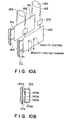
- each actuator 170 comprises a bellowphragm 171 shown in Figure 13, will be explained.
- the bellowphragm 171 includes a bellows 171b having an air supply port 171a.
- the upper end of the bellows 171b is coupled to a first housing 171c which is integral with the Y stage 120.
- the lower end of the bellows 171b is connected to a second housing 171d, connected to the lower end of the belt 162.
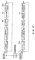
- Figure 17 is a block diagram of a control system for controlling the inside air pressure of the bellows 171b, on the basis of positional information of the X stage 130 in X-axis direction.
- Serve system for controlling X linear motor 150 controls the drive amount of the X linear motor 150, on the basis of a position designation value supplied thereto from a computer (not shown) and of positional information of the X stage 130 in X-axis direction as fed back from the position sensor 130d.
- the position designation value described above is kp transformed, and the result is supplied to a controller 171a (control means) together with a pressure designation value of a bellowphragm control system.
- a servo valve connected to the air supply inlet 171a of the bellowphragm 171 is adjusted, whereby the inside air pressure within the bellows 171b is controlled.
- the position designation value of the X stage 130 is multiplied by a conversion coefficient kp and a pressure designation value of the bellowphragm control system is added. Then, as the gravity position of the stage movable portion shifts, inside pressure of each bellows 171 is changed to adjust the tension of each belt 162. In this manner, the tensions of belts 162 are adjusted individually. This produces rotational moment opposite to the rotational moment, produced with the movement of the X stage 130. As a result, loads to be applied to the Y guide 111 are reduced.
- actuator 170 comprising bellowphragm 171, air cylinder 172 or linear motor 173, for example, or of an elastic member such as a laminated rubber member 174, will be explained in greater detail.
- PID Proportion Kp, Integration Ki and Differentiation Kd
- gain adjustment is made so that the gain crossover frequency with which the servo rigidity ⁇ d/ ⁇ e becomes lowest is set to about 100 Hz.
- each actuator 120 comprises an air cylinder 172 ( Figure 14) in place of bellowphragm 171
- the cylinder 172b having an air supply port 172a is made integral with the Y stage 120.
- the belt 162 has its lower end connected to the piston 172c. By changing the pressure of air to be supplied to the air supply inlet 172a, the tension of the belt 162 is adjusted.
- a control system for controlling the air pressure of the cylinder 172b may be similar to that shown in Figure 17.
- each actuator 170 comprises a linear motor 173 shown in Figure 15, the following applies.
- the coil 173a of the linear motor 173 is integral with the Y stage 120, and the belt 162 has its lower end connected to a driving magnet 173b.
- a control system for controlling the electric current to be supplied to the coil 173a may be similar to that of Figure 17.
- the laminated rubber member 174 shown in Figure 16 has its upper end connected to a housing 174a which is integral with the Y stage 120.
- the lower end of the rubber member 174 is supported by a housing 174b, connected to the belt 162.
- a housing 174b Through elastic change in thickness of the laminated rubber member 174, vibration propagation from the belt 162 to the Y stage 120 is prevented.
- the laminated rubber member 174 may be replaced by a piezoelectric device which can function as an actuator.
- the housing 174a supporting the upper end of the piezoelectric device may be integral with the Y stage 120, while a housing 174b for supporting the lower end of the piezoelectric device 174 may be connected to the lower end of the belt 162.
- a control system for controlling the electric voltage to be supplied to the piezoelectric device may be similar to that of Figure 17.
- vibration propagation from the countermass 161 to the Y stage 120 may be of low frequency as a few Hz, for further improvement of positioning precision and for attainment of higher speed, it may be undesirable.
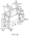
- third driving means comprising a pair of linear motors 180 ( Figure 12) may preferably be added to accelerate the countermass 161 in opposite direction to the Y stage 120, to thereby suppress the natural vibration of the countermass 161.
- the linear motors 180 may be provided at opposite ends of the countermass 161, and they may be disposed at the back of the Y linear motor 140 for moving the Y stage 120 in Y-axis direction.
- Each linear motor 180 is provided with a linear motor movable element 181 integral with the countermass 161, which element is movable along a linear motor stator 182 provided at a side edge of the stage base 110.
- a linear motor stator 182 By controlling electric current to be supplied to the linear motor stator 182, acceleration of the countermass 161 in Y-axis direction can be adjusted to one having the same absolute value as and in opposite direction to the acceleration as provided by the Y linear motor 140 to the Y stage 120. By doing so, it is possible to substantially completely remove external disturbance due to natural vibration of the countermass 161.
- a control system for the linear motor 180 for driving the countermass 161 will be described later with reference to the block diagram of Figure 18.
- Figure 18 shows a control system for linear motors 180, for driving the countermass 161 in Y-axis direction.
- Servo system for controlling the Y linear motor 140 controls the driving amount of the Y linear motor 140 on the basis of a position designation value as supplied from a computer (not shown) and of positional information of the Y stage 120 in Y-axis direction as fed back from the position sensor 130c.
- the position designation value is applied to the linear motor 180 of the countermass 161, as an acceleration designation value being twice differentiated and kp converted. Only with the addition of such a simple control system as described above, the driving amounts of the Y stage 120 and of the countermass 161 can be controlled synchronously.
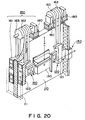
- FIG 20 shows an eighth embodiment of the present invention.
- actuators 180 are provided at the bearing portion (supporting portion) of pulleys 163 disposed at the top of the stage base 110.
- each actuator 180 comprises bellowphragms 181 provided between the stage base 110 and a bearing base 163b on which a rolling bearing 163a for rotatably supporting the pulley 163 is mounted.
- the inside structure of the bellowphragm 181 may be similar to that of the bellowphragm 171 of Figure 13. It is controlled with a control system similar to that of Figure 17.
- an air cylinder In place of the bellowphragm, an air cylinder, a linear motor, or a laminated rubber member such as shown in Figures 14 - 16 may be used.
- stage base 110 As regards stage base 110, Y guide 111, Y stage 120, X stage 130, Y linear motor 140, X linear motor 150, countermass mechanism 160 and so on, they may be similar to those of the seventh embodiment. Description therefor will be omitted, by assigning corresponding reference numerals to them.
- an actuator or elastic member for adjusting the tension or effective length of the belt may be provided at the support of the pulley.
- similar actuator means may be provided at the connection between the countermass and the belt at the back of the stage base, with a similar advantage of effective correction or prevention of rotational moment.
- a rotary type static pressure bearing 190 shown in Figure 22 may be used to rotatably support the pulley 163.
- the rotary type static bearing 190 comprises a pair of bearing members 190a for supporting the bearing portion of the pulley 163 with respect to a radial direction and a thrust direction, without contact thereto. It serves to resiliently change the height of the pulley 163 within the range as determined by the bearing gap 190b of the bearing member 190a. With the damper effect as described, vibration propagation from the belt 162 to the Y stage 120 can be prevented.
- FIG 23 shows a ninth embodiment of the present invention.
- a weight compensation mechanism 200 is used wherein a pulley 263 is rotationally driven by a weight compensation motor 203 which produces a torque that balances with the weight of stage movable portion, including the Y stage 120 and X stage 130. More specifically, each motor 203 rotates the pulley 263 to wind up the belt 262, to thereby cancel the weight of the stage movable portion.
- Each of the belts 262 and the Y stage 202 (Y slider 221) are connected to each other through an actuator 210 (anti-vibration means).
- stage base 210 As regards stage base 210, Y guide 211, Y stage 220, X stage 230, Y linear motor 240, X linear motor 250 and so on, they may be similar to those of the first embodiment, and description therefor will be omitted.
- actuators 210 As for actuators 210, a bellowphragm 171, an air cylinder 172 or a linear motor 173 shown in Figures 13 - 15 may be used. In place of the actuator 210, an elastic member such as rubber member 174 of Figure 16 or a piezoelectric device may be used.
- an actuator or elastic member having an anti-vibration function may be added. This largely contributes to improvement of speed and precision of the stage system.
- the actuators may be controlled on the basis of positional information about the X stage to perform rotational moment correction, similarly to the seventh and eighth embodiments.
- the actuator or elastic member may be provided at the connection between the Y stage and the belt, as shown in Figure 23. Alternatively, it may be provided at the support for the bearing portion of the pulley.
- an elastic member such as a laminated rubber member may be provided on the surface of a pulley for winding the belt, to thereby absorb belt vibration.
- FIG. 24 is a schematic view of an X-ray exposure apparatus according to an embodiment of the present invention.
- Synchrotron radiation light emitted from a synchrotron radiation producing device 301 (X-ray source) impinges on a mirror 302 disposed at a predetermined distance from the light emission point.
- the mirror 302 has a convex surface shape, and it expands the synchrotron radiation light of sheet-like beam from the synchrotron radiation source 301. Although only one mirror is illustrated, plural mirrors may be used for expansion of the synchrotron radiation.
- the synchrotron radiation light reflected by the mirror passes through a transmission type mask M (original) having a pattern of X-ray absorptive material, formed on an X-ray transmissive film, by which the light is transformed into a desired pattern shape and is projected on a substrate W (wafer).
- the wafer is coated with a resist material (photosensitive material).
- the wafer W is held by a wafer chuck 303 of a stage system, according to any one of the preceding embodiments of the present invention described above.
- the wafer chuck 303 is mounted on a main stage (not shown).
- a shutter 304 Disposed upstream of the mask M is a shutter 304 for controlling exposure time over the whole exposure region.
- the shutter 304 is actuated by a shutter driving unit 304a which is controlled by a shutter control unit 304b.
- a beryllium film (not shown) is provided between the mirror 302 and the shutter 304. The mirror side of this beryllium film is maintained at super vacuum, while the shutter side thereof is maintained at reduced pressure He.
- an exposure apparatus which meets increases of speed and precision is provided.
- FIG 25 is a flow chart of procedure for manufacture of microdevices such as semiconductor chips (e.g. ICs or LSIs), liquid crystal panels, CCDs, thin film magnetic heads or micro-machines, for example.
- Step 1 is a design process for designing a circuit of a semiconductor device.
- Step 2 is a process for making a mask on the basis of the circuit pattern design.
- Step 3 is a process for preparing a wafer by using a material such as silicon.
- Step 4 is a wafer process which is called a pre-process wherein, by using the so prepared mask and wafer, circuits are practically formed on the wafer through lithography.
- Step 5 subsequent to this is an assembling step which is called a post-process wherein the wafer having been processed by step 4 is formed into semiconductor chips.
- This step includes assembling (dicing and bonding) process and packaging (chip sealing) process.
- Step 6 is an inspection step wherein operation check, durability check and so on for the semiconductor devices provided by step 5, are carried out. With these processes, semiconductor devices are completed and they are shipped (step 7).
- Step 26 is a flow chart showing details of the wafer process.
- Step 11 is an oxidation process for oxidizing the surface of a wafer.
- Step 12 is a CVD process for forming an insulating film on the wafer surface.
- Step 13 is an electrode forming process for forming electrodes upon the wafer by vapor deposition.
- Step 14 is an ion implanting process for implanting ions to the wafer.
- Step 15 is a resist process for applying a resist (photosensitive material) to the wafer.
- Step 16 is an exposure process for printing, by exposure, the circuit pattern of the mask on the wafer through the exposure apparatus described above.
- Step 17 is a developing process for developing the exposed wafer.
- Step 18 is an etching process for removing portions other than the developed resist image.
- Step 19 is a resist separation process for separating the resist material remaining on the wafer after being subjected to the etching process. By repeating these processes, circuit patterns are superposedly formed on the wafer.
Priority Applications (1)
| Application Number | Priority Date | Filing Date | Title |
|---|---|---|---|
| TR2001/01314T TR200101314T2 (tr) | 1998-11-10 | 1999-10-25 | Ağartıcı deterjan bileşimleri |
Applications Claiming Priority (12)
| Application Number | Priority Date | Filing Date | Title |
|---|---|---|---|
| JP30860797 | 1997-11-11 | ||
| JP308607/97 | 1997-11-11 | ||
| JP30860797A JP3890127B2 (ja) | 1997-11-11 | 1997-11-11 | ステージ装置およびこれを用いた露光装置、ならびにデバイス製造方法 |
| JP10114219A JPH11297616A (ja) | 1998-04-09 | 1998-04-09 | ステージ装置およびこれを用いた露光装置ならびにデバイス製造方法 |
| JP11421998 | 1998-04-09 | ||
| JP114119/98 | 1998-04-09 | ||
| JP114219/98 | 1998-04-09 | ||
| JP114208/98 | 1998-04-09 | ||
| JP11411998 | 1998-04-09 | ||
| JP10114208A JPH11297795A (ja) | 1998-04-09 | 1998-04-09 | ステージ装置およびこれを用いた露光装置ならびにデバイス製造方法 |
| JP10114119A JPH11297613A (ja) | 1998-04-09 | 1998-04-09 | ステージ装置およびこれを用いた露光装置ならびにデバイス製造方法 |
| JP11420898 | 1998-04-09 |
Publications (2)
| Publication Number | Publication Date |
|---|---|
| EP0917004A2 true EP0917004A2 (fr) | 1999-05-19 |
| EP0917004A3 EP0917004A3 (fr) | 2000-05-24 |
Family
ID=27470142
Family Applications (1)
| Application Number | Title | Priority Date | Filing Date |
|---|---|---|---|
| EP98309167A Withdrawn EP0917004A3 (fr) | 1997-11-11 | 1998-11-10 | Système de dispositifs porte-objet et appareil d'exposition avec un tel système |
Country Status (3)
| Country | Link |
|---|---|
| US (1) | US6408045B1 (fr) |
| EP (1) | EP0917004A3 (fr) |
| KR (1) | KR100278263B1 (fr) |
Cited By (15)
| Publication number | Priority date | Publication date | Assignee | Title |
|---|---|---|---|---|
| WO2001027978A1 (fr) * | 1999-10-07 | 2001-04-19 | Nikon Corporation | Substrat, dispositif a etage, procede d'attaque d'etage, systeme d'exposition et procede d'exposition |
| EP1111470A2 (fr) * | 1999-12-21 | 2001-06-27 | Asm Lithography B.V. | Appareil lithographique avec un système de positionnement équilibré |
| EP1211560A1 (fr) * | 2000-12-04 | 2002-06-05 | Nikon Corporation | Porte-objet actionné par gaz comprenant un mécanisme pour annuler les forces de réaction pour être utilisé dans un système de lithographie utilisant un faisceau de particules chargées |
| EP1321822A1 (fr) * | 2001-12-21 | 2003-06-25 | ASML Netherlands B.V. | Appareil lithographique et méthode pour la fabrication d un dispositif |
| EP1369745A1 (fr) | 2002-06-07 | 2003-12-10 | ASML Netherlands B.V. | Appareil lithographique et méthode de fabrication d'un dispositif |
| EP1463185A2 (fr) | 2003-03-28 | 2004-09-29 | Tokyo Seimitsu Co.,Ltd. | Unité d'entrainement uniaxiale et dispositif de mesure de formes les utilisant |
| EP1486824A1 (fr) * | 2003-06-11 | 2004-12-15 | ASML Netherlands B.V. | Système porte-objet mobile pour un appareil d'exposition, appareil d'exposition et méthode de fabrication d'un dispositif |
| WO2006075209A2 (fr) | 2005-01-13 | 2006-07-20 | Prima Industrie S.P.A. | Machine-outil laser |
| DE102006038455A1 (de) * | 2006-08-16 | 2008-02-21 | Carl Zeiss Smt Ag | Optisches System für die Halbleiterlithographie |
| WO2008117197A1 (fr) | 2007-03-27 | 2008-10-02 | Koninklijke Philips Electronics, N.V. | Conception d'étages à axes séparés pour des applications semi-conductrices |
| DE102012017130A1 (de) | 2012-09-01 | 2014-03-06 | Man Diesel & Turbo Se | Laser-Rohreinschweißen |
| CN103698984A (zh) * | 2013-12-17 | 2014-04-02 | 嘉兴华嶺机电设备有限公司 | 一种超精扫描镀膜及定位光刻设备 |
| EP2862670A1 (fr) * | 2010-03-02 | 2015-04-22 | Fives Landis Limited | Méchanisme de compensation d'une force et procédé d'opération de ce méchanisme |
| CN110270842A (zh) * | 2018-03-14 | 2019-09-24 | 发那科株式会社 | 校正量取得装置及方法、进给机构控制装置及方法 |
| CN115741209A (zh) * | 2022-11-21 | 2023-03-07 | 绍兴格洛博动力总成有限公司 | 一种机床重力平衡装置及立式稳定机床 |
Families Citing this family (47)
| Publication number | Priority date | Publication date | Assignee | Title |
|---|---|---|---|---|
| US6558878B1 (en) * | 1999-07-08 | 2003-05-06 | Korea Electronics Technology Institute | Microlens manufacturing method |
| EP1248288A1 (fr) * | 1999-12-16 | 2002-10-09 | Nikon Corporation | Procede et dispositif d'exposition |
| TW546551B (en) * | 1999-12-21 | 2003-08-11 | Asml Netherlands Bv | Balanced positioning system for use in lithographic apparatus |
| JP2002075855A (ja) * | 2000-06-14 | 2002-03-15 | Canon Inc | 自重補償装置およびこれを用いたステージ装置並びに露光装置およびそれを用いたデバイス製造方法 |
| US6757053B1 (en) * | 2000-11-16 | 2004-06-29 | Nikon Corporation | Stage assembly including a reaction mass assembly |
| US6593997B1 (en) * | 2000-11-16 | 2003-07-15 | Nikon Corporation | Stage assembly including a reaction assembly |
| US6603531B1 (en) * | 2000-11-16 | 2003-08-05 | Nikon Corporation | Stage assembly including a reaction assembly that is connected by actuators |
| US6809486B2 (en) * | 2000-12-15 | 2004-10-26 | Stirling Technology Company | Active vibration and balance system for closed cycle thermodynamic machines |
| US20020117969A1 (en) * | 2001-02-28 | 2002-08-29 | Nikon Corporation | Magnetic shielding devices and methods involving active cancellation of external magnetic fields at the column of a charged-particle-beam optical system |
| US6828890B2 (en) * | 2001-09-26 | 2004-12-07 | Engineering Matters, Inc. | High intensity radial field magnetic array and actuator |
| US7061577B2 (en) | 2002-03-26 | 2006-06-13 | Nikon Corporation | Image adjustor including damping assembly |
| US6724466B2 (en) | 2002-03-26 | 2004-04-20 | Nikon Corporation | Stage assembly including a damping assembly |
| JP4109891B2 (ja) * | 2002-04-19 | 2008-07-02 | キヤノン株式会社 | 能動制振装置、露光装置及びデバイス製造方法 |
| JP4012024B2 (ja) * | 2002-09-10 | 2007-11-21 | キヤノン株式会社 | 位置決め装置に於ける衝撃吸収装置 |
| US6876284B2 (en) | 2002-09-26 | 2005-04-05 | Engineering Matters, Inc. | High intensity radial field magnetic array and actuator |
| US7352268B2 (en) * | 2002-09-26 | 2008-04-01 | Engineering Matters, Inc. | High intensity radial field magnetic actuator |
| US6963821B2 (en) * | 2003-02-11 | 2005-11-08 | Nikon Corporation | Stage counter mass system |
| US20040160132A1 (en) * | 2003-02-14 | 2004-08-19 | Carter Frederick Michael | System and method to reduce the effect of reactive forces on a stage using a balance mass |
| JP2004253741A (ja) * | 2003-02-21 | 2004-09-09 | Sumitomo Eaton Noba Kk | 移動装置及び半導体製造装置 |
| US20040252287A1 (en) * | 2003-06-11 | 2004-12-16 | Michael Binnard | Reaction frame assembly that functions as a reaction mass |
| JP3781421B2 (ja) * | 2003-07-23 | 2006-05-31 | キヤノン株式会社 | 位置決め方法および位置決め本体装置 |
| JP2005086029A (ja) * | 2003-09-09 | 2005-03-31 | Canon Inc | 位置決めステージ装置及び露光装置並びに半導体デバイスの製造方法 |
| JP4093156B2 (ja) * | 2003-09-11 | 2008-06-04 | セイコーエプソン株式会社 | 半導体装置製造用治具、半導体装置製造方法および半導体装置 |
| JP4314091B2 (ja) * | 2003-10-03 | 2009-08-12 | キヤノン株式会社 | 露光装置及びデバイス製造方法 |
| JP2005203567A (ja) * | 2004-01-15 | 2005-07-28 | Canon Inc | 駆動装置、露光装置及びデバイス製造方法 |
| JP4478470B2 (ja) * | 2004-01-26 | 2010-06-09 | キヤノン株式会社 | 位置決めステージ装置 |
| US7221433B2 (en) | 2004-01-28 | 2007-05-22 | Nikon Corporation | Stage assembly including a reaction assembly having a connector assembly |
| US20050261559A1 (en) * | 2004-05-18 | 2005-11-24 | Mumford John R | Wireless physiological monitoring system |
| JP4655039B2 (ja) | 2004-06-07 | 2011-03-23 | 株式会社ニコン | ステージ装置、露光装置及び露光方法 |
| JP2006032788A (ja) * | 2004-07-20 | 2006-02-02 | Canon Inc | 露光装置及び半導体デバイスの製造方法 |
| ITTO20040647A1 (it) * | 2004-09-28 | 2004-12-28 | Prima Ind Spa | Punzonatrice laser |
| JP2006120798A (ja) * | 2004-10-20 | 2006-05-11 | Canon Inc | 露光装置 |
| US7557529B2 (en) * | 2005-01-11 | 2009-07-07 | Nikon Corporation | Stage unit and exposure apparatus |
| JP4731977B2 (ja) * | 2005-04-22 | 2011-07-27 | キヤノン株式会社 | 光学機器 |
| JP4834439B2 (ja) * | 2006-03-30 | 2011-12-14 | キヤノン株式会社 | ステージ装置及びその制御方法、露光装置及びデバイス製造方法 |
| US8387945B2 (en) * | 2009-02-10 | 2013-03-05 | Engineering Matters, Inc. | Method and system for a magnetic actuator |
| US8659746B2 (en) * | 2009-03-04 | 2014-02-25 | Nikon Corporation | Movable body apparatus, exposure apparatus and device manufacturing method |
| US8735774B2 (en) * | 2009-03-27 | 2014-05-27 | Electro Scientific Industries, Inc. | Force reaction compensation system |
| JPWO2010131490A1 (ja) * | 2009-05-15 | 2012-11-01 | 株式会社ニコン | 露光装置及びデバイス製造方法 |
| US8724115B2 (en) | 2011-09-06 | 2014-05-13 | Kla-Tencor Corporation | Linear stage and metrology architecture for reflective electron beam lithography |
| WO2013036615A1 (fr) * | 2011-09-06 | 2013-03-14 | Kla-Tencor Corporation | Étage linéaire pour lithographie par faisceau d'électrons réfléchissant |
| CN104889951A (zh) * | 2015-06-08 | 2015-09-09 | 广东工业大学 | 动态特性可调宏微一体化复合平台 |
| CN112763521A (zh) * | 2015-06-30 | 2021-05-07 | 伊利诺斯工具制品有限公司 | 联机x射线测量设备和方法 |
| US10031427B2 (en) * | 2015-09-30 | 2018-07-24 | Applied Materials, Inc. | Methods and apparatus for vibration damping stage |
| KR20180077991A (ko) * | 2016-12-29 | 2018-07-09 | 삼성전자주식회사 | 의료기기 |
| CN111266631A (zh) * | 2020-03-28 | 2020-06-12 | 福州脉弧科技有限公司 | 一种纳米板材钻孔设备 |
| JP2022061834A (ja) * | 2020-10-07 | 2022-04-19 | キヤノン株式会社 | 位置決め装置、リソグラフィ装置及び物品の製造方法 |
Citations (5)
| Publication number | Priority date | Publication date | Assignee | Title |
|---|---|---|---|---|
| EP0360272A2 (fr) * | 1988-09-22 | 1990-03-28 | Fujitsu Limited | Dispositif de séquence pour la formation de circuits intégrés |
| US4993696A (en) * | 1986-12-01 | 1991-02-19 | Canon Kabushiki Kaisha | Movable stage mechanism |
| EP0501724A2 (fr) * | 1991-02-25 | 1992-09-02 | Canon Kabushiki Kaisha | Support |
| EP0557100A1 (fr) * | 1992-02-21 | 1993-08-25 | Canon Kabushiki Kaisha | Système de commande de porte-objets |
| GB2290658A (en) * | 1994-06-27 | 1996-01-03 | Nikon Corp | Electromagnetic alignment and scanning apparatus |
Family Cites Families (18)
| Publication number | Priority date | Publication date | Assignee | Title |
|---|---|---|---|---|
| US5040431A (en) | 1988-01-22 | 1991-08-20 | Canon Kabushiki Kaisha | Movement guiding mechanism |
| JP2770960B2 (ja) * | 1988-10-06 | 1998-07-02 | キヤノン株式会社 | Sor−x線露光装置 |
| US5280677A (en) | 1990-05-17 | 1994-01-25 | Canon Kabushiki Kaisha | Positioning mechanism |
| US5684856A (en) * | 1991-09-18 | 1997-11-04 | Canon Kabushiki Kaisha | Stage device and pattern transfer system using the same |
| JP2714502B2 (ja) * | 1991-09-18 | 1998-02-16 | キヤノン株式会社 | 移動ステージ装置 |
| US5298939A (en) * | 1991-11-04 | 1994-03-29 | Swanson Paul A | Method and apparatus for transfer of a reticle pattern onto a substrate by scanning |
| DE69412719T2 (de) * | 1993-06-24 | 1999-02-18 | Canon Kk | Steuerung für einen mehrphasigen Motor |
| JP3196798B2 (ja) | 1993-10-12 | 2001-08-06 | キヤノン株式会社 | 自重支持装置 |
| JPH07115056A (ja) | 1993-10-15 | 1995-05-02 | Canon Inc | 縦型基板ステージ装置 |
| JP3226704B2 (ja) | 1994-03-15 | 2001-11-05 | キヤノン株式会社 | 露光装置 |
| JPH08229759A (ja) | 1995-02-24 | 1996-09-10 | Canon Inc | 位置決め装置並びにデバイス製造装置及び方法 |
| US5806193A (en) * | 1995-11-09 | 1998-09-15 | Nikon Corporation | Tilt and movement apparatus using flexure and air cylinder |
| JP3634483B2 (ja) | 1996-02-13 | 2005-03-30 | キヤノン株式会社 | ステージ装置、及びこれを用いた露光装置やデバイス生産方法 |
| US5930324A (en) * | 1996-04-03 | 1999-07-27 | Canon Kabushiki Kaisha | Exposure apparatus and device manufacturing method using the same |
| JP3659529B2 (ja) * | 1996-06-06 | 2005-06-15 | キヤノン株式会社 | 露光装置およびデバイス製造方法 |
| JP3266515B2 (ja) * | 1996-08-02 | 2002-03-18 | キヤノン株式会社 | 露光装置、デバイス製造方法およびステージ装置 |
| US6028376A (en) * | 1997-04-22 | 2000-02-22 | Canon Kabushiki Kaisha | Positioning apparatus and exposure apparatus using the same |
| JPH1184098A (ja) * | 1997-07-11 | 1999-03-26 | Canon Inc | X線照明装置およびx線照明方法、x線露光装置ならびにデバイス製造方法 |
-
1998
- 1998-11-06 US US09/187,408 patent/US6408045B1/en not_active Expired - Fee Related
- 1998-11-10 EP EP98309167A patent/EP0917004A3/fr not_active Withdrawn
- 1998-11-11 KR KR1019980048200A patent/KR100278263B1/ko not_active IP Right Cessation
Patent Citations (5)
| Publication number | Priority date | Publication date | Assignee | Title |
|---|---|---|---|---|
| US4993696A (en) * | 1986-12-01 | 1991-02-19 | Canon Kabushiki Kaisha | Movable stage mechanism |
| EP0360272A2 (fr) * | 1988-09-22 | 1990-03-28 | Fujitsu Limited | Dispositif de séquence pour la formation de circuits intégrés |
| EP0501724A2 (fr) * | 1991-02-25 | 1992-09-02 | Canon Kabushiki Kaisha | Support |
| EP0557100A1 (fr) * | 1992-02-21 | 1993-08-25 | Canon Kabushiki Kaisha | Système de commande de porte-objets |
| GB2290658A (en) * | 1994-06-27 | 1996-01-03 | Nikon Corp | Electromagnetic alignment and scanning apparatus |
Non-Patent Citations (1)
| Title |
|---|
| UCHIDA N ET AL: "A vertical X-Y stage for X-ray lithography using SOR" BULLETIN OF THE JAPAN SOCIETY OF PRECISION ENGINEERING, JUNE 1988, JAPAN, vol. 22, no. 2, pages 102-108, XP000892597 ISSN: 0582-4206 * |
Cited By (30)
| Publication number | Priority date | Publication date | Assignee | Title |
|---|---|---|---|---|
| WO2001027978A1 (fr) * | 1999-10-07 | 2001-04-19 | Nikon Corporation | Substrat, dispositif a etage, procede d'attaque d'etage, systeme d'exposition et procede d'exposition |
| EP1111470A2 (fr) * | 1999-12-21 | 2001-06-27 | Asm Lithography B.V. | Appareil lithographique avec un système de positionnement équilibré |
| EP1111470A3 (fr) * | 1999-12-21 | 2004-03-10 | ASML Netherlands B.V. | Appareil lithographique avec un système de positionnement équilibré |
| EP1211560A1 (fr) * | 2000-12-04 | 2002-06-05 | Nikon Corporation | Porte-objet actionné par gaz comprenant un mécanisme pour annuler les forces de réaction pour être utilisé dans un système de lithographie utilisant un faisceau de particules chargées |
| US6674085B2 (en) | 2000-12-04 | 2004-01-06 | Nikin Corporation | Gas-actuated stages including reaction-force-canceling mechanisms for use in charged-particle-beam microlithography systems |
| EP1321823A3 (fr) * | 2001-12-21 | 2005-02-09 | ASML Netherlands B.V. | Appareil lithographique et méthode pour la production d'un dispositif |
| EP1321822A1 (fr) * | 2001-12-21 | 2003-06-25 | ASML Netherlands B.V. | Appareil lithographique et méthode pour la fabrication d un dispositif |
| EP1321823A2 (fr) * | 2001-12-21 | 2003-06-25 | ASML Netherlands B.V. | Appareil lithographique et méthode pour la production d'un dispositif |
| EP1369745A1 (fr) | 2002-06-07 | 2003-12-10 | ASML Netherlands B.V. | Appareil lithographique et méthode de fabrication d'un dispositif |
| EP1369745B1 (fr) * | 2002-06-07 | 2013-02-27 | ASML Netherlands B.V. | Appareil lithographique et méthode de fabrication d'un dispositif |
| EP1463185A3 (fr) * | 2003-03-28 | 2006-10-11 | Tokyo Seimitsu Co.,Ltd. | Unité d'entrainement uniaxiale et dispositif de mesure de formes les utilisant |
| US7239050B2 (en) | 2003-03-28 | 2007-07-03 | Tokyo Seimitsu Co., Ltd. | Uniaxial drive unit and surface shape measuring apparatus using the same |
| EP1463185A2 (fr) | 2003-03-28 | 2004-09-29 | Tokyo Seimitsu Co.,Ltd. | Unité d'entrainement uniaxiale et dispositif de mesure de formes les utilisant |
| US7110086B2 (en) | 2003-06-11 | 2006-09-19 | Asml Netherlands B.V. | Movable stage system, lithographic apparatus, and device manufacturing method |
| EP1486824A1 (fr) * | 2003-06-11 | 2004-12-15 | ASML Netherlands B.V. | Système porte-objet mobile pour un appareil d'exposition, appareil d'exposition et méthode de fabrication d'un dispositif |
| CN101142051B (zh) * | 2005-01-13 | 2011-04-06 | 普瑞玛工业股份有限公司 | 激光机床 |
| US7910857B2 (en) | 2005-01-13 | 2011-03-22 | Prima Industrie S.P.A. | Laser machine tool |
| WO2006075209A2 (fr) | 2005-01-13 | 2006-07-20 | Prima Industrie S.P.A. | Machine-outil laser |
| WO2006075209A3 (fr) * | 2005-01-13 | 2006-09-28 | Prima Ind Spa | Machine-outil laser |
| DE102006038455A1 (de) * | 2006-08-16 | 2008-02-21 | Carl Zeiss Smt Ag | Optisches System für die Halbleiterlithographie |
| US9383544B2 (en) | 2006-08-16 | 2016-07-05 | Carl Zeiss Smt Gmbh | Optical system for semiconductor lithography |
| WO2008117197A1 (fr) | 2007-03-27 | 2008-10-02 | Koninklijke Philips Electronics, N.V. | Conception d'étages à axes séparés pour des applications semi-conductrices |
| US9789578B2 (en) | 2010-03-02 | 2017-10-17 | Fives Landis Limited | Counterforce mechanism and methods of operation thereof |
| EP2862670A1 (fr) * | 2010-03-02 | 2015-04-22 | Fives Landis Limited | Méchanisme de compensation d'une force et procédé d'opération de ce méchanisme |
| DE102012017130A1 (de) | 2012-09-01 | 2014-03-06 | Man Diesel & Turbo Se | Laser-Rohreinschweißen |
| CN103698984A (zh) * | 2013-12-17 | 2014-04-02 | 嘉兴华嶺机电设备有限公司 | 一种超精扫描镀膜及定位光刻设备 |
| CN103698984B (zh) * | 2013-12-17 | 2017-01-04 | 嘉兴华嶺机电设备有限公司 | 一种超精扫描镀膜及定位光刻设备 |
| CN110270842A (zh) * | 2018-03-14 | 2019-09-24 | 发那科株式会社 | 校正量取得装置及方法、进给机构控制装置及方法 |
| CN110270842B (zh) * | 2018-03-14 | 2020-09-22 | 发那科株式会社 | 校正量取得装置及方法、进给机构控制装置及方法 |
| CN115741209A (zh) * | 2022-11-21 | 2023-03-07 | 绍兴格洛博动力总成有限公司 | 一种机床重力平衡装置及立式稳定机床 |
Also Published As
| Publication number | Publication date |
|---|---|
| KR19990045193A (ko) | 1999-06-25 |
| KR100278263B1 (ko) | 2001-01-15 |
| EP0917004A3 (fr) | 2000-05-24 |
| US6408045B1 (en) | 2002-06-18 |
Similar Documents
| Publication | Publication Date | Title |
|---|---|---|
| US6408045B1 (en) | Stage system and exposure apparatus with the same | |
| JP3947501B2 (ja) | リソグラフィ用機器およびデバイスの製造方法 | |
| US6862077B2 (en) | Anti-vibration system for exposure apparatus | |
| US6028376A (en) | Positioning apparatus and exposure apparatus using the same | |
| JP3971868B2 (ja) | 位置決め装置、およびその装置を含んで成る平板印刷投影装置 | |
| KR100570252B1 (ko) | 리소그래피 장치에 사용하는 균형화 위치결정 시스템 | |
| US6472840B1 (en) | Vibration cancellation apparatus and exposure apparatus | |
| US6999162B1 (en) | Stage device, exposure system, method of device manufacture, and device | |
| US6885430B2 (en) | System and method for resetting a reaction mass assembly of a stage assembly | |
| US20070097340A1 (en) | Active damper with counter mass to compensate for structural vibrations of a lithographic system | |
| US6987558B2 (en) | Reaction mass for a stage device | |
| KR20010067456A (ko) | 전사 장치용 균형화 위치결정시스템 | |
| US6958808B2 (en) | System and method for resetting a reaction mass assembly of a stage assembly | |
| US6731372B2 (en) | Multiple chamber fluid mount | |
| JP3890127B2 (ja) | ステージ装置およびこれを用いた露光装置、ならびにデバイス製造方法 | |
| US7333179B2 (en) | Moving mechanism with high bandwidth response and low force transmissibility | |
| EP1369745B1 (fr) | Appareil lithographique et méthode de fabrication d'un dispositif | |
| US20040057817A1 (en) | Switchable damping mechanism for use in a stage apparatus | |
| US20030169412A1 (en) | Reaction frame for a wafer scanning stage with electromagnetic connections to ground | |
| US20040004703A1 (en) | Method and apparatus for reducing rotary stiffness in a support mechanism | |
| JPH11297613A (ja) | ステージ装置およびこれを用いた露光装置ならびにデバイス製造方法 | |
| JP2002175963A (ja) | ステージ装置とその位置制御方法および露光装置並びに露光方法 | |
| JP4011919B2 (ja) | 移動装置及び露光装置並びに半導体デバイスの製造方法 | |
| US20040187616A1 (en) | Bellows lateral stiffness adjustment | |
| JPH11297616A (ja) | ステージ装置およびこれを用いた露光装置ならびにデバイス製造方法 |
Legal Events
| Date | Code | Title | Description |
|---|---|---|---|
| PUAI | Public reference made under article 153(3) epc to a published international application that has entered the european phase |
Free format text: ORIGINAL CODE: 0009012 |
|
| AK | Designated contracting states |
Kind code of ref document: A2 Designated state(s): DE GB NL |
|
| AX | Request for extension of the european patent |
Free format text: AL;LT;LV;MK;RO;SI |
|
| PUAL | Search report despatched |
Free format text: ORIGINAL CODE: 0009013 |
|
| AK | Designated contracting states |
Kind code of ref document: A3 Designated state(s): AT BE CH CY DE DK ES FI FR GB GR IE IT LI LU MC NL PT SE |
|
| AX | Request for extension of the european patent |
Free format text: AL;LT;LV;MK;RO;SI |
|
| 17P | Request for examination filed |
Effective date: 20001009 |
|
| 17Q | First examination report despatched |
Effective date: 20001129 |
|
| AKX | Designation fees paid |
Free format text: DE GB NL |
|
| STAA | Information on the status of an ep patent application or granted ep patent |
Free format text: STATUS: THE APPLICATION HAS BEEN WITHDRAWN |
|
| 18W | Application withdrawn |
Effective date: 20091214 |