EP0914918B1 - Prothèse tubulaire poreuse et méthode pour sa fabrication par co-aspersion sur un mandrin en rotation de composés solubles et non-solubles à l'eau - Google Patents
Prothèse tubulaire poreuse et méthode pour sa fabrication par co-aspersion sur un mandrin en rotation de composés solubles et non-solubles à l'eau Download PDFInfo
- Publication number
- EP0914918B1 EP0914918B1 EP98303484A EP98303484A EP0914918B1 EP 0914918 B1 EP0914918 B1 EP 0914918B1 EP 98303484 A EP98303484 A EP 98303484A EP 98303484 A EP98303484 A EP 98303484A EP 0914918 B1 EP0914918 B1 EP 0914918B1
- Authority
- EP
- European Patent Office
- Prior art keywords
- prosthesis
- water soluble
- mandrel
- component
- fibrous
- Prior art date
- Legal status (The legal status is an assumption and is not a legal conclusion. Google has not performed a legal analysis and makes no representation as to the accuracy of the status listed.)
- Expired - Lifetime
Links
- XLYOFNOQVPJJNP-UHFFFAOYSA-N water Substances O XLYOFNOQVPJJNP-UHFFFAOYSA-N 0.000 title claims description 108
- 238000000034 method Methods 0.000 title claims description 54
- 238000005507 spraying Methods 0.000 title claims description 41
- 239000000835 fiber Substances 0.000 claims description 133
- 239000002904 solvent Substances 0.000 claims description 62
- 239000000203 mixture Substances 0.000 claims description 61
- 229920001223 polyethylene glycol Polymers 0.000 claims description 47
- 239000002202 Polyethylene glycol Substances 0.000 claims description 46
- 229920000642 polymer Polymers 0.000 claims description 31
- YMWUJEATGCHHMB-UHFFFAOYSA-N Dichloromethane Chemical compound ClCCl YMWUJEATGCHHMB-UHFFFAOYSA-N 0.000 claims description 21
- 239000011248 coating agent Substances 0.000 claims description 21
- 238000000576 coating method Methods 0.000 claims description 21
- 239000002243 precursor Substances 0.000 claims description 16
- 229920002050 silicone resin Polymers 0.000 claims description 14
- 238000004519 manufacturing process Methods 0.000 claims description 13
- 238000009835 boiling Methods 0.000 claims description 8
- UOCLXMDMGBRAIB-UHFFFAOYSA-N 1,1,1-trichloroethane Chemical compound CC(Cl)(Cl)Cl UOCLXMDMGBRAIB-UHFFFAOYSA-N 0.000 claims description 7
- 239000003480 eluent Substances 0.000 claims description 4
- 229920005989 resin Polymers 0.000 claims description 4
- 239000011347 resin Substances 0.000 claims description 4
- 150000001335 aliphatic alkanes Chemical class 0.000 claims description 3
- 238000005406 washing Methods 0.000 claims description 2
- 239000007921 spray Substances 0.000 claims 3
- XUIMIQQOPSSXEZ-UHFFFAOYSA-N Silicon Chemical compound [Si] XUIMIQQOPSSXEZ-UHFFFAOYSA-N 0.000 claims 1
- 229910052710 silicon Inorganic materials 0.000 claims 1
- 239000010703 silicon Substances 0.000 claims 1
- 229920001296 polysiloxane Polymers 0.000 description 48
- 239000007787 solid Substances 0.000 description 25
- 238000007590 electrostatic spraying Methods 0.000 description 20
- 239000000463 material Substances 0.000 description 20
- 238000004626 scanning electron microscopy Methods 0.000 description 18
- 239000006185 dispersion Substances 0.000 description 15
- 239000012530 fluid Substances 0.000 description 13
- -1 polyethylene terephthalate Polymers 0.000 description 12
- 238000004804 winding Methods 0.000 description 11
- 230000008569 process Effects 0.000 description 10
- 230000000052 comparative effect Effects 0.000 description 8
- 238000001035 drying Methods 0.000 description 8
- 238000010998 test method Methods 0.000 description 8
- 238000013459 approach Methods 0.000 description 7
- 238000001125 extrusion Methods 0.000 description 6
- 239000007788 liquid Substances 0.000 description 6
- 238000012545 processing Methods 0.000 description 6
- 150000003839 salts Chemical class 0.000 description 6
- 230000002792 vascular Effects 0.000 description 6
- 210000004027 cell Anatomy 0.000 description 5
- 238000010828 elution Methods 0.000 description 5
- 239000002195 soluble material Substances 0.000 description 5
- OFBQJSOFQDEBGM-UHFFFAOYSA-N Pentane Chemical compound CCCCC OFBQJSOFQDEBGM-UHFFFAOYSA-N 0.000 description 4
- 229920002594 Polyethylene Glycol 8000 Polymers 0.000 description 4
- 239000004372 Polyvinyl alcohol Substances 0.000 description 4
- 230000009286 beneficial effect Effects 0.000 description 4
- 239000003795 chemical substances by application Substances 0.000 description 4
- 150000002148 esters Chemical class 0.000 description 4
- 239000000155 melt Substances 0.000 description 4
- 239000002861 polymer material Substances 0.000 description 4
- 229920002451 polyvinyl alcohol Polymers 0.000 description 4
- 239000011148 porous material Substances 0.000 description 4
- 125000006850 spacer group Chemical group 0.000 description 4
- 238000009987 spinning Methods 0.000 description 4
- 208000007536 Thrombosis Diseases 0.000 description 3
- 208000027418 Wounds and injury Diseases 0.000 description 3
- 230000008901 benefit Effects 0.000 description 3
- 238000004364 calculation method Methods 0.000 description 3
- 238000004581 coalescence Methods 0.000 description 3
- 238000005516 engineering process Methods 0.000 description 3
- 238000002474 experimental method Methods 0.000 description 3
- 238000005259 measurement Methods 0.000 description 3
- 239000002245 particle Substances 0.000 description 3
- 229920002379 silicone rubber Polymers 0.000 description 3
- LFQSCWFLJHTTHZ-UHFFFAOYSA-N Ethanol Chemical compound CCO LFQSCWFLJHTTHZ-UHFFFAOYSA-N 0.000 description 2
- 229920002845 Poly(methacrylic acid) Polymers 0.000 description 2
- 239000004952 Polyamide Substances 0.000 description 2
- 229920002125 Sokalan® Polymers 0.000 description 2
- 230000009471 action Effects 0.000 description 2
- 150000001298 alcohols Chemical class 0.000 description 2
- 230000001413 cellular effect Effects 0.000 description 2
- 230000008878 coupling Effects 0.000 description 2
- 238000010168 coupling process Methods 0.000 description 2
- 238000005859 coupling reaction Methods 0.000 description 2
- 230000006378 damage Effects 0.000 description 2
- 230000001419 dependent effect Effects 0.000 description 2
- 238000011161 development Methods 0.000 description 2
- 229920001971 elastomer Polymers 0.000 description 2
- 125000004185 ester group Chemical group 0.000 description 2
- 125000001495 ethyl group Chemical group [H]C([H])([H])C([H])([H])* 0.000 description 2
- 238000011156 evaluation Methods 0.000 description 2
- 239000008187 granular material Substances 0.000 description 2
- 238000002513 implantation Methods 0.000 description 2
- 125000002496 methyl group Chemical group [H]C([H])([H])* 0.000 description 2
- 229920002432 poly(vinyl methyl ether) polymer Polymers 0.000 description 2
- 229920002401 polyacrylamide Polymers 0.000 description 2
- 239000004584 polyacrylic acid Substances 0.000 description 2
- 229920002647 polyamide Polymers 0.000 description 2
- 229920006324 polyoxymethylene Polymers 0.000 description 2
- 229920002635 polyurethane Polymers 0.000 description 2
- 239000004814 polyurethane Substances 0.000 description 2
- 239000005060 rubber Substances 0.000 description 2
- 229920002994 synthetic fiber Polymers 0.000 description 2
- 230000001225 therapeutic effect Effects 0.000 description 2
- 229920001169 thermoplastic Polymers 0.000 description 2
- 229920001187 thermosetting polymer Polymers 0.000 description 2
- 239000004416 thermosoftening plastic Substances 0.000 description 2
- SCYULBFZEHDVBN-UHFFFAOYSA-N 1,1-Dichloroethane Chemical compound CC(Cl)Cl SCYULBFZEHDVBN-UHFFFAOYSA-N 0.000 description 1
- HEDRZPFGACZZDS-UHFFFAOYSA-N Chloroform Chemical compound ClC(Cl)Cl HEDRZPFGACZZDS-UHFFFAOYSA-N 0.000 description 1
- 102000016359 Fibronectins Human genes 0.000 description 1
- 108010067306 Fibronectins Proteins 0.000 description 1
- 229940123457 Free radical scavenger Drugs 0.000 description 1
- 229920002683 Glycosaminoglycan Polymers 0.000 description 1
- CTQNGGLPUBDAKN-UHFFFAOYSA-N O-Xylene Chemical compound CC1=CC=CC=C1C CTQNGGLPUBDAKN-UHFFFAOYSA-N 0.000 description 1
- 229930182556 Polyacetal Natural products 0.000 description 1
- 229920002732 Polyanhydride Polymers 0.000 description 1
- 239000004695 Polyether sulfone Substances 0.000 description 1
- 229920002582 Polyethylene Glycol 600 Polymers 0.000 description 1
- 239000004642 Polyimide Substances 0.000 description 1
- 229920001710 Polyorthoester Polymers 0.000 description 1
- 239000004743 Polypropylene Substances 0.000 description 1
- 208000024248 Vascular System injury Diseases 0.000 description 1
- 208000012339 Vascular injury Diseases 0.000 description 1
- 230000002411 adverse Effects 0.000 description 1
- 238000004458 analytical method Methods 0.000 description 1
- 239000005557 antagonist Substances 0.000 description 1
- 239000003242 anti bacterial agent Substances 0.000 description 1
- 230000002927 anti-mitotic effect Effects 0.000 description 1
- 230000001028 anti-proliverative effect Effects 0.000 description 1
- 229940088710 antibiotic agent Drugs 0.000 description 1
- 239000003146 anticoagulant agent Substances 0.000 description 1
- 229940127219 anticoagulant drug Drugs 0.000 description 1
- 239000004599 antimicrobial Substances 0.000 description 1
- 239000003080 antimitotic agent Substances 0.000 description 1
- 239000003963 antioxidant agent Substances 0.000 description 1
- 239000003124 biologic agent Substances 0.000 description 1
- 230000015572 biosynthetic process Effects 0.000 description 1
- 230000017531 blood circulation Effects 0.000 description 1
- 210000004204 blood vessel Anatomy 0.000 description 1
- 230000001680 brushing effect Effects 0.000 description 1
- 230000008859 change Effects 0.000 description 1
- 229960001701 chloroform Drugs 0.000 description 1
- 238000004891 communication Methods 0.000 description 1
- 239000004020 conductor Substances 0.000 description 1
- 238000003618 dip coating Methods 0.000 description 1
- 238000009826 distribution Methods 0.000 description 1
- 238000012377 drug delivery Methods 0.000 description 1
- 239000013536 elastomeric material Substances 0.000 description 1
- 210000002889 endothelial cell Anatomy 0.000 description 1
- 239000003822 epoxy resin Substances 0.000 description 1
- 230000009477 glass transition Effects 0.000 description 1
- PCHJSUWPFVWCPO-UHFFFAOYSA-N gold Chemical compound [Au] PCHJSUWPFVWCPO-UHFFFAOYSA-N 0.000 description 1
- 239000010931 gold Substances 0.000 description 1
- 229910052737 gold Inorganic materials 0.000 description 1
- 239000003102 growth factor Substances 0.000 description 1
- LNEPOXFFQSENCJ-UHFFFAOYSA-N haloperidol Chemical compound C1CC(O)(C=2C=CC(Cl)=CC=2)CCN1CCCC(=O)C1=CC=C(F)C=C1 LNEPOXFFQSENCJ-UHFFFAOYSA-N 0.000 description 1
- 238000010438 heat treatment Methods 0.000 description 1
- 229920001903 high density polyethylene Polymers 0.000 description 1
- 239000004700 high-density polyethylene Substances 0.000 description 1
- 206010020718 hyperplasia Diseases 0.000 description 1
- 239000003018 immunosuppressive agent Substances 0.000 description 1
- 229940125721 immunosuppressive agent Drugs 0.000 description 1
- 239000004615 ingredient Substances 0.000 description 1
- 238000010128 melt processing Methods 0.000 description 1
- 238000002844 melting Methods 0.000 description 1
- 230000008018 melting Effects 0.000 description 1
- 239000002184 metal Substances 0.000 description 1
- 229910052751 metal Inorganic materials 0.000 description 1
- 229940021182 non-steroidal anti-inflammatory drug Drugs 0.000 description 1
- 230000003287 optical effect Effects 0.000 description 1
- 239000011368 organic material Substances 0.000 description 1
- 239000003960 organic solvent Substances 0.000 description 1
- 238000004806 packaging method and process Methods 0.000 description 1
- 229920001568 phenolic resin Polymers 0.000 description 1
- 239000005011 phenolic resin Substances 0.000 description 1
- 229920003023 plastic Polymers 0.000 description 1
- 239000004033 plastic Substances 0.000 description 1
- 239000002745 poly(ortho ester) Substances 0.000 description 1
- 239000004417 polycarbonate Substances 0.000 description 1
- 229920000515 polycarbonate Polymers 0.000 description 1
- 229920000647 polyepoxide Polymers 0.000 description 1
- 229920000728 polyester Polymers 0.000 description 1
- 229920006393 polyether sulfone Polymers 0.000 description 1
- 229920000139 polyethylene terephthalate Polymers 0.000 description 1
- 239000005020 polyethylene terephthalate Substances 0.000 description 1
- 229920001721 polyimide Polymers 0.000 description 1
- 239000002952 polymeric resin Substances 0.000 description 1
- 229920001155 polypropylene Polymers 0.000 description 1
- 229920001343 polytetrafluoroethylene Polymers 0.000 description 1
- 239000004810 polytetrafluoroethylene Substances 0.000 description 1
- 230000000644 propagated effect Effects 0.000 description 1
- 102000004169 proteins and genes Human genes 0.000 description 1
- 108090000623 proteins and genes Proteins 0.000 description 1
- 239000002516 radical scavenger Substances 0.000 description 1
- 230000003439 radiotherapeutic effect Effects 0.000 description 1
- 230000008439 repair process Effects 0.000 description 1
- 239000013557 residual solvent Substances 0.000 description 1
- 238000005096 rolling process Methods 0.000 description 1
- 239000012056 semi-solid material Substances 0.000 description 1
- 238000000926 separation method Methods 0.000 description 1
- 239000004945 silicone rubber Substances 0.000 description 1
- 239000011343 solid material Substances 0.000 description 1
- 238000010129 solution processing Methods 0.000 description 1
- 239000007858 starting material Substances 0.000 description 1
- 150000003431 steroids Chemical class 0.000 description 1
- 239000002731 stomach secretion inhibitor Substances 0.000 description 1
- 239000000126 substance Substances 0.000 description 1
- 229920003002 synthetic resin Polymers 0.000 description 1
- 238000012360 testing method Methods 0.000 description 1
- 238000012956 testing procedure Methods 0.000 description 1
- 230000002885 thrombogenetic effect Effects 0.000 description 1
- 229960000103 thrombolytic agent Drugs 0.000 description 1
- 230000002537 thrombolytic effect Effects 0.000 description 1
- 238000013519 translation Methods 0.000 description 1
- 208000019553 vascular disease Diseases 0.000 description 1
- 229940124549 vasodilator Drugs 0.000 description 1
- 239000003071 vasodilator agent Substances 0.000 description 1
- 229920003176 water-insoluble polymer Polymers 0.000 description 1
- 239000008096 xylene Substances 0.000 description 1
Images


Classifications
-
- B—PERFORMING OPERATIONS; TRANSPORTING
- B29—WORKING OF PLASTICS; WORKING OF SUBSTANCES IN A PLASTIC STATE IN GENERAL
- B29C—SHAPING OR JOINING OF PLASTICS; SHAPING OF MATERIAL IN A PLASTIC STATE, NOT OTHERWISE PROVIDED FOR; AFTER-TREATMENT OF THE SHAPED PRODUCTS, e.g. REPAIRING
- B29C41/00—Shaping by coating a mould, core or other substrate, i.e. by depositing material and stripping-off the shaped article; Apparatus therefor
- B29C41/02—Shaping by coating a mould, core or other substrate, i.e. by depositing material and stripping-off the shaped article; Apparatus therefor for making articles of definite length, i.e. discrete articles
- B29C41/08—Coating a former, core or other substrate by spraying or fluidisation, e.g. spraying powder
- B29C41/085—Coating a former, core or other substrate by spraying or fluidisation, e.g. spraying powder by rotating the former around its axis of symmetry
-
- A—HUMAN NECESSITIES
- A61—MEDICAL OR VETERINARY SCIENCE; HYGIENE
- A61F—FILTERS IMPLANTABLE INTO BLOOD VESSELS; PROSTHESES; DEVICES PROVIDING PATENCY TO, OR PREVENTING COLLAPSING OF, TUBULAR STRUCTURES OF THE BODY, e.g. STENTS; ORTHOPAEDIC, NURSING OR CONTRACEPTIVE DEVICES; FOMENTATION; TREATMENT OR PROTECTION OF EYES OR EARS; BANDAGES, DRESSINGS OR ABSORBENT PADS; FIRST-AID KITS
- A61F2/00—Filters implantable into blood vessels; Prostheses, i.e. artificial substitutes or replacements for parts of the body; Appliances for connecting them with the body; Devices providing patency to, or preventing collapsing of, tubular structures of the body, e.g. stents
- A61F2/02—Prostheses implantable into the body
- A61F2/04—Hollow or tubular parts of organs, e.g. bladders, tracheae, bronchi or bile ducts
- A61F2/06—Blood vessels
- A61F2/062—Apparatus for the production of blood vessels made from natural tissue or with layers of living cells
-
- B—PERFORMING OPERATIONS; TRANSPORTING
- B29—WORKING OF PLASTICS; WORKING OF SUBSTANCES IN A PLASTIC STATE IN GENERAL
- B29K—INDEXING SCHEME ASSOCIATED WITH SUBCLASSES B29B, B29C OR B29D, RELATING TO MOULDING MATERIALS OR TO MATERIALS FOR MOULDS, REINFORCEMENTS, FILLERS OR PREFORMED PARTS, e.g. INSERTS
- B29K2105/00—Condition, form or state of moulded material or of the material to be shaped
- B29K2105/04—Condition, form or state of moulded material or of the material to be shaped cellular or porous
-
- B—PERFORMING OPERATIONS; TRANSPORTING
- B29—WORKING OF PLASTICS; WORKING OF SUBSTANCES IN A PLASTIC STATE IN GENERAL
- B29K—INDEXING SCHEME ASSOCIATED WITH SUBCLASSES B29B, B29C OR B29D, RELATING TO MOULDING MATERIALS OR TO MATERIALS FOR MOULDS, REINFORCEMENTS, FILLERS OR PREFORMED PARTS, e.g. INSERTS
- B29K2995/00—Properties of moulding materials, reinforcements, fillers, preformed parts or moulds
- B29K2995/0037—Other properties
- B29K2995/0059—Degradable
-
- B—PERFORMING OPERATIONS; TRANSPORTING
- B29—WORKING OF PLASTICS; WORKING OF SUBSTANCES IN A PLASTIC STATE IN GENERAL
- B29L—INDEXING SCHEME ASSOCIATED WITH SUBCLASS B29C, RELATING TO PARTICULAR ARTICLES
- B29L2031/00—Other particular articles
- B29L2031/753—Medical equipment; Accessories therefor
- B29L2031/7532—Artificial members, protheses
- B29L2031/7534—Cardiovascular protheses
Definitions
- the present invention generally relates to porous prostheses and to methods of making the same. More particularly, the invention relates to porous prostheses and methods of making the same wherein the prostheses are formed by spraying fibers onto a rotating mandrel under conditions such that the resultant prostheses have a porous inner surface, more preferably both porous inner and outer surfaces.
- prostheses also referred to as stents or grafts
- a typical treatment involves implanting a prosthesis to replace and/or repair portions of damaged or diseased blood vessels.
- prostheses have been formed from both natural and synthetic materials. As between natural and synthetic materials, much attention has been focused upon the development and use of acceptable synthetic prostheses formed from materials such as polymers or the like.
- Porous structures are currently preferred as such porous structures, after implantation in a host, tend to become covered with a lining of thrombus. Thus, the surface of the structure exposed to blood flow i.e., the flow surface, becomes less thrombogenic over time. Accordingly, synthetic prostheses desirably exhibit a certain amount of porosity effective to help promote tissue ingrowth that results in the formation of a lining of thrombus. Porosity is desirable on both the inner and outer surfaces of a prosthesis, but is particularly desirable on the inner, or flow, surface.
- the quality and quantity of the porosity of the inner surface of a synthetic prosthesis is highly dependent upon the manner in which the prosthesis is made.
- some synthetic prostheses have been made from compositions comprising a biocompatible, water insoluble elastomeric resin and a water soluble salt. After a prosthesis is formed from such a composition, the salt is rinsed out using hot water. The voids in the prosthesis formerly occupied by the salt contribute to the porosity of the inner wall of the prosthesis.
- This approach has a number of drawbacks, however.
- the resultant pore shape tends to correspond to the crystalline shape of the salt, and therefore tends to have sharp edges and corners. These sharp edges and corners can act like stress concentrators from which stresses are easily propagated. This has a negative impact upon the mechanical strength of the prosthesis.
- a relatively high concentration of salt is generally required to achieve desired levels of porosity, which also can result in a mechanically weak prosthesis.
- Synthetic prostheses with some porosity have also been prepared using the so-called continuous fiber winding technique.
- a polymer melt, solution, or dispersion is extruded through a fine orifice to form a polymeric fiber.
- the resultant polymeric fiber is then continuously wound onto a rotating mandrel.
- the circumferential velocity of the mandrel is generally higher than the velocity by which the fiber is extruded so that considerable stretching of the fiber takes place during winding. Because the fiber is still hot (melt processing) or still contains solvent (solution processing) when it reaches the mandrel, fiber-fiber binding takes place. After a number of passes, the desired thickness is reached.
- the fibrous structure may then be dried, cured, cooled, and removed from the mandrel.
- a porous, stable tube can result.
- the use of such a continuous fiber winding technique to form a porous prosthesis has been described in Leidner et al., "A Novel Process for the Manufacturing of Porous Grafts: Process Description and Product Evaluation," J. of Biomedical Materials Res., Vol. 17, No. 2, March 1983, pp. 229-247.
- EP-A-0,143,638 discloses a method for making a porous tubular structure for biomedical applications comprising as the starting materials two polymer solutions having dispersed therein water soluble particles of different size. Co-extruding these dispersions results in an intermediate tubular structure from which their dispersed material is eluted. The resulted product comprises a polymer open porous structure.
- US-A-3,700,380 describes a polymer lining or intermediate polymer layer having micro cavities. This can be produced by incorporating fibres, particles or granules into a polymer layer from which, after curing this layer, said fibres, particles or granules can be leached, leaving said micro cavities in the polymer layer.
- US-A-4,738,740 describes vascular grafts having an external surface with a porous structure.
- the grafts are prepared by winding an extruded fibre onto a mandrel in the presence of intermittently applied electrostatic forces.
- said vascular graft does not comprise a fibrous, porous structure, i.e. fibrous shaped voids.
- continuous fibre winding provides a prosthesis with a fibrous structure, which is very desirable in terms of performance (e.g. tissue ingrowth) and mechanical properties such as strength, compliance, flexibility and the like.
- continuous fibre winding techniques may only be used in connection with polymeric materials that are spinnable, e.g. good fibre formers.
- polymer materials without such good fibre forming characteristics that nontheless have other characteristics that are extremely desirable in the manufacture and subsequent use of prostheses.
- silicone resins are a class of materials that are desirable in terms of strength, compliance, flexibility, biocompatibility, elasticity, and the like, but are not spinnable fiber formers. Consequently, silicone resins and similar materials generally are not compatible with the continuous fiber winding technique.
- Electrostatic spraying is a technique that may be used to form a fibrous prostheses from a wide range of polymer materials, (including polymers such as silicone resins) that are otherwise poor fiber formers.
- a polymer melt, solution, or dispersion is extruded through a fine orifice and directed toward a rotating mandrel.
- a voltage is maintained between the orifice and mandrel so that the polymer material is attracted electrostatically to the mandrel.
- droplets of the polymer material extruded from the orifice are electrostatically pulled toward the mandrel.
- the mandrel is thus struck with a plurality of short polymeric fibers that eventually coat the mandrel.
- a desired thickness of material can be built up, after which the resultant prosthesis can be dried, cured, cooled, and removed from the mandrel.
- the conventional electrostatic spraying technique suffers from some drawbacks.
- the short polymeric fibers tend to coalesce after striking the mandrel, at least to some degree. This causes the inner wall of the resultant prosthesis to have low, if any, porosity.
- Silicone fibers, in/particular tend to coalesce when electrostatically sprayed onto a mandrel to such a degree that the inner wall of the prosthesis is substantially smooth.
- prosthesis produced by the electrostatic spraying of silicone tend to lack the degree of porosity that would facilitate the desired ingrowth of host tissue.
- prostheses can be electrostatically sprayed from polymeric materials, particularly silicone fibers and other polymers that are poor fiber formers, in such a way that the prostheses have a beneficial degree of porosity on the inner wall surfaces.
- a fibrous, synthetic prosthesis with at least inner wall porosity can be formed on a suitable mold (preferably a rotating mandrel) by electrostatically spraying at least one water insoluble, polymeric fibrous component and at least one, separate water soluble fibrous component onto the mandrel to form a tubular prosthesis.
- a suitable mold preferably a rotating mandrel
- the fibrous components may be electrostatically sprayed onto the mandrel until the tubular prosthesis has the desired wall thickness. Electrostatic spraying may then be stopped, after which the fibrous component(s) may be dried, solidified, and/or cured (as appropriate depending upon how the fibrous components are to be provided).
- the water soluble fibrous component then may be washed out of, i.e., eluted from, the tubular prosthesis using an appropriate solvent, such as hot water. Elution leaves fibrous shaped voids in the tubular structure that provide the resultant prosthesis with the desired porosity.
- the amount of porosity, the location of the porosity, and the mechanical properties of the resultant prosthesis are easy to control merely by varying easily adjusted parameters in the electrostatic spraying process such as the rotational speed of the mandrel, the flow rate of the sprayed materials onto the mandrel, the temperature at which the fibrous components are wound onto the mandrel, the solids content of polymer solutions used to form the fibers in embodiments using polymer solutions, combinations of these, and the like.
- this approach provides a prosthesis with not only a fibrous physical structure provided by the water insoluble fibrous component, but also a fibrous porosity structure resulting from elution of the water soluble fiber component. Both fibrous features contribute to the mechanical strength of the prosthesis.
- the "fibrous" porosity characteristics of the present invention generally benefit from substantially less stress concentrating features.
- the method of the present invention effectively produces a porous prosthesis due to the utilization of a water soluble fibrous component in combination with a water insoluble fibrous component.
- the water soluble fibrous component being insoluble in the water insoluble fibrous component, acts as a physical spacer and helps to prevent and/or at least substantially reduce fiber coalescence that might otherwise occur in the absence of the water soluble fibers.
- the present invention relates to a method of forming a porous, tubular, synthetic prosthesis as clamed in Claim 1.
- a prosthesis comprising a tubular body having an inner wall surface and an outer wall surface, said body comprising a fibrous, elastomeric, polymer structure characterised in that said body comprises fibrous shaped voids.
- the present invention relates to a method of making a tubular prosthesis precursor.
- a water insoluble polymeric fibrous component and a water soluble fibrous component are co-sprayed onto a mold to form the tubular prosthesis precursor comprising the water soluble fibrous component and a water insoluble polymeric fibrous component.
- Another aspect of the present invention relates to a prosthesis precursor comprising a tubular body comprising a water insoluble polymeric fibrous component and a water soluble component.
- FIG. 1 illustrates a particularly preferred approach in which the principles of the present invention may be practiced to form prosthesis 9.
- this approach involves electrostatically co-spraying water insoluble, fiber forming composition 32 and a separate water soluble fiber forming composition 33 around a prosthesis mold, e.g. rotating mandrel 12.
- the resultant prosthesis 9 will thus comprise water insoluble fibrous component 34 and water soluble fibrous component 35, keeping in mind that portions of the solvents (if any) originally in these components at the time of spraying may not be present in prosthesis 9 due to volatilization.
- water soluble fibrous component 35 acts like a spacer between windings of water insoluble fibrous component 34, the presence of water soluble fibrous component 35 helps to prevent coalescence of water insoluble fibrous component 34.
- the water soluble fiber component 35 is easily removed from prosthesis 9 by washing the prosthesis with water or any similar eluent.
- this leaves voids in the spaces formerly occupied by water soluble fibrous component 35, thus providing prosthesis 9 with a substantially higher level of porosity than would result if no water soluble fibrous component 35 were to have been co-sprayed with water insoluble fibrous component 34.
- FIG. 1 shows electrostatic spraying device 10 that includes mandrel assembly 11 including a prosthesis mold in the form of rotating mandrel 12.
- Mandrel 12 is rotatably driven by motor 14, which is mounted to base 16 upon motor support 18.
- the rotational output of motor 14 is controllably variable so that the rotational speed of mandrel 12 can be adjusted as desired.
- One end 20 of mandrel 12 is gripped in the jaws of chuck 22, which in turn is operationally mounted to motor 14 by coupler 24.
- the opposite end 26 of mandrel 12 is rotatably journalled in bearings 28 supported in mandrel support 30.
- the exterior diameter of mandrel 12 will determine the inner diameter size of prosthesis 9.
- Device 10 is configured, therefore, so that mandrel 12 is easily removed and replaced with a mandrel having a different diameter, allowing prosthesis 9 to be formed with any desired inner diameter within a wide size range merely be choosing and inserting an appropriately sized mandrel into device 10.
- fiber diameter of each of fiber components 34 and 35 typically is independently in the range from 10 micrometers to 100 micrometers, preferably 20 micrometers to 50 micrometers, and mandrel rotational speed typically is in the range from about 200 rpm to about 2200 rpm, preferably 1500 rpm to 2000 rpm.
- the corresponding average pore size typically will be in the range from about 10 micrometers to about 200 micrometers, preferably from about 20 micrometers to about 80 micrometers, more preferably about 30 micrometers for vascular application.
- Water insoluble fibrous component 34 is formed by extruding water insoluble fiber forming composition 32 from fiber forming subassembly 40, and water-soluble fibrous component 35 is formed by extruding water soluble fiber forming composition 33 from fiber forming subassembly 41.
- Fiber forming subassemblies 40 and 41 respectively comprise cylinders 42 and 43 in which hydraulic fluid chambers 44 and 45 are separated from fiber forming composition chambers 48 and 49 by plungers 50 and 51. Chambers 44 and 45 are filled with hydraulic fluid 46 and 47 and fiber forming composition chambers 48 and 49 are filled with fiber forming compositions 32 and 33.
- Needles 38 and 39 are in fluid communication with chambers 48 and 49 and provide orifices through which fiber forming compositions 32 and 33 may be extruded to form fibrous components 34 and 35 as a consequence of pressure developed by downward movement of plungers 50 and 51.
- Needles 38 and 39 generally are independently formed from a conductive material to facilitate the use of the electrostatic spraying technique when forming prosthesis 9, and may be of any suitable shapes and sizes.
- each of needles 38 and 39 may be 23 to 25 gauge in size and may have a length of 3 cm.
- the distance between needles 38 and 39 is not critical. However, less material from fiber forming compositions 32 and 33 is wasted with each pass as the needle spacing is reduced. In typical applications, such spacing may range from about 1 mm to about 4 cm, preferably from about 1 cm to about 2 cm.
- Hydraulic fluids 46 and 47 may be any suitable hydraulic gas or liquid, although a liquid, such as an alcohol, is presently preferred. Desirably, the rate at which pumps 52 and 53 motivate hydraulic fluids 46 and 47 into chambers 44 and 45 is independently controllable so that the rates of extrusion of fiber forming compositions 32 and 33 can be adjusted over a wide operating range. The particular rates at which volumetric pumps 52 and 53 motivate hydraulic fluids 46 and 47 into chambers 44 and 45 may thus be varied depending on the nature of the fiber forming composition 32 and 33.
- fiber forming composition 32 comprises 20 parts by weight of a silicone resin and 80 parts by weight of solvent
- rates of extrusion in the range of from about 0.1 ml/min to about 0.6 ml/min have been found to be suitable.
- the desired extrusion rate of fiber forming composition 33 relative to fiber forming composition 32 will be described in more detail below.
- Cylinders 42 and 43 are supported upon fixture 80 (shown in Figures 3a, 3b, 4a and 4c). Fixture 80 further supports needles 38 and 39 at a suitable distance from mandrel 12 for carrying out fiber forming and spraying operations. In general, better fibers are formed as this distance is increased. However, if the distance is too great, fibrous component 34 may be too dry upon reaching mandrel 12, so that poor fiber-fiber bonding results. On the other hand, if the distance is too small, portions of fibrous component 34 may have a greater tendency to coalesce around mandrel 12. Generally, the optimum distance may be easily determined empirically for any one particular fiber forming composition 32 using routine testing procedures.
- fiber forming composition 32 comprises about 20 to 30 parts by weight of a silicone resin and 80 parts by weight of solvent
- a distance of 20 mm to 200 mm from needles 38 and 39 to mandrel 12 has been found to be suitable. Greater distances are preferred so long as adequate fiber-fiber bonding is achieved.
- Needles 38 and 39 move axially back and forth relative to mandrel 12 so that prosthesis 9 is formed along a length of mandrel 12.
- This relative axial movement of needle 38 is represented schematically by arrow 58a in Figure 1, which shows needles 38 and 39 moving to the right relative to mandrel 12.
- needles 38 and 39 would move to the left relative to mandrel 12.
- the relative axial movement between needles 38 and 39 and mandrel 12 can be accomplished by causing actual axial movement of the needles 38 and 39 and/or mandrel 12.
- needles 38 and 39 remain stationary while mandrel 12 is translated axially back and forth using any suitable translation device to accomplish such movement.
- Power for such movement can be provided by motor 14 or by another power source (not shown) if desired.
- the speed of axial movement may be in the range effective to provide angles ⁇ 1 , and ⁇ 2 of from about 10° to about 85°, preferably about 45° between the sprayed material and mandrel 12.
- a typical translational speed, for example, is about 400 cm/min.
- the electrostatic spraying technique involves extruding fiber components 34 and 35 from needles 38 and 39 under conditions such that fibrous components 34 and 35 are electrostatically attracted to mandrel 12 during spraying operations. This is accomplished by developing a voltage between needles 38 and 39 and mandrel 12 by electrically coupling high voltage terminal 60 of power source 62 to mandrel 12 and low voltage terminal 64 to needles 38 and 39. Of course, it is also possible to electrically couple high voltage terminal 60 of power source 62 to needles 38 and 39 and low voltage terminal 64 to mandrel 12, if desired. Generally, the attraction between mandrel 12 and fibrous components 34 and 35 increases as the voltage between mandrel 12 and needles 38 and 39 is increased.
- Figure 2 shows the coupling between power source 62 and mandrel 12 in more detail. Specifically, Figure 2 shows a portion of end 26 of mandrel 12 projecting from mandrel support 30. As shown, mandrel support 30 includes top 66 releasably secured to bottom 68 by screws 70. Top 66 can thus be removed from bottom 68 in order to remove and replace mandrel 12. Mandrel support 30 also includes block 75 attached to bottom 68. Wire 72 from power source 62 ( Figure 1) is connected to terminal 74. Terminal 74, in turn, is electrically coupled to mandrel 12 by resilient metal strip 76.
- mandrel 12 and needles 38 and 39 are desirably electrically isolated from motor 14 as well as the environment.
- base 16, supports 18 and 30, and coupler 24 are desirably formed of a structurally sound, insulating, polymeric material.
- Fixture 80 may also include similar materials (not shown) in similar fashion.
- a wide range of polymers may be used for this insulating purpose, including one or more polyurethanes, polyacetals, polyamides, polyimides, epoxy resins, phenolic resins, combinations of these, and the like.
- the insulating polymer is a polyacetal commercially available from E.I DuPont de Nemours & Co. under the tradename DELRYN.
- portions of electrostatic spraying device 10, including mandrel assembly 11 and cylinders 42 and 43, may be housed in an insulative enclosure (not shown) having a door (not shown) equipped with a safety interlock that disables power source 62 when the door is open.
- the door may be fitted with a clear, insulating plastic panel allowing operations to be observed but offering further protection against the voltage developed by power source 62.
- power source 62, pumps 52 and 53, and motor speed controls can be installed outside of the enclosure so that the operator does not have to open the door to the enclosure to gain access to these devices.
- Fiber forming composition 32 preferably may be any extrudable composition comprising a biocompatible, water insoluble, thermoplastic or thermosetting, elastomeric polymer or combination of polymers from which fiber component 34 may be formed and then electrostatically sprayed around mandrel 12.
- Preferred elastomeric polymers have an elongation at break of at least 200%, preferably from about 200% to about 800% and have a longitudinal tensile force at break in the range of 1 kg/cm 2 to 17 kg/cm 2 .
- the elastomeric polymers utilized as fiber forming composition 32 have tensile characteristics so that the resultant prosthesis 9 preferably has a radial tensile force at break in the range of 1 kg/cm 2 to 20 kg/cm 2 .
- elastomeric polymers suitable for use in fiber forming composition 32 include silicone, high density polyethylene, polyethylene terephthalate, polyurethane, polyamide, polyester, polyorthoester, polyanhydride, polyether sulfone, polycarbonate, polypropylene, polytetrafluoroethylene, combinations of these, or the like. Of these, a thermosetting silicone resin is preferred.
- a suitable silicone resin is commercially available under the trade designation 40000 from Applied Silicone Corp.
- this resin When cured per the guidelines provided by the vendor (1 hour at 150°C), this resin has a durometer hardness, Shore A units, of 35, a tensile strength of 126 Kg/cm 2 (1800 psi.) and an elongation at break of about 800%.
- This polymer may be obtained as a 35% solids solution in xylene, or more preferably as a 29% solids solution in trichloroethane.
- Another example of a suitable silicone resin is commercially available under the trade designation MED-4865 from NuSil Silicone Technology.
- this resin When cured per the guidelines provided by the vendor (10 minutes at 180°C), this resin has a durometer hardness, Shore A units, of 65, a tensile strength of 84 Kg/cm 2 (1200 psi.), and an elongation at break of about 500%.
- This polymer may be obtained "neat", i.e., at 100% solids.
- fiber forming composition 32 may further comprise one or more optional therapeutic ingredients such as anticoagulants, thrombolytics, steroids, vasodilators, antimicrobials or antibiotics, antimitotics, antiproliferatives, antisecretory agents, non-steroidal anti-inflammatory drugs, immunosuppressive agents, growth factor antagonists, free radical scavengers, antioxidants, biologic agents, radiotherapeutic agents, radiopaque agents and radiolabelled agents, combinations of these, and the like in accordance with conventional practices.
- optional therapeutic ingredients such as anticoagulants, thrombolytics, steroids, vasodilators, antimicrobials or antibiotics, antimitotics, antiproliferatives, antisecretory agents, non-steroidal anti-inflammatory drugs, immunosuppressive agents, growth factor antagonists, free radical scavengers, antioxidants, biologic agents, radiotherapeutic agents, radiopaque agents and radiolabelled agents, combinations of these, and the like in accordance with conventional practices.
- Fiber forming composition 32 preferably is in an extrudable fluid form such as a melt, a solution, or a dispersion. More preferably, fiber forming composition 32 is a solution or dispersion comprising one or more water insoluble polymers as described above dissolved (solution) or dispersed (dispersion) in a suitable organic solvent. Fiber forming composition 32 should comprise a sufficient amount of solvent so that fiber forming composition 32 has an appropriate viscosity to carry out extrusion and fiber forming operations. As general guidelines, fiber forming composition 32 may comprise about 80 parts by weight of solvent per 10 to 160 parts by weight of polymer. In a particularly preferred embodiment of the invention, fiber forming composition 32 comprises 20 parts by weight of a silicone resin and 80 parts by weight of solvent.
- a wide variety of solvents or combination of solvents may be incorporated into fiber forming composition 32.
- the type of solvent utilized will depend upon a number of factors, such as the type of polymer being used, the desired solvent drying rate, the temperature at which operations are carried out, and the like. Additionally, the solvent utilized should have a drying rate so that the fibers are not too wet or too dry at the time of striking mandrel 12. If the solvent evaporates too quickly i.e., the fibers are too dry, poor fiber-fiber bonding may result. If the solvent evaporates too slowly, i.e., the fibers are too wet, the fibers will have a greater tendency to coalesce together. The resultant prosthesis may have low or no, porosity.
- an otherwise suitable solvent having a less than optimum drying rate can be accommodated by adjusting the distance between needle 38 and mandrel 12. For example, if the solvent dries relatively slowly, increasing the distance from needle 38 to mandrel 12 will provide the solvent with more time to evaporate so that the fibers are not too wet. If the solvent dries too quickly, reducing the distance from needle 38 to mandrel 12 will reduce the amount of time the solvent has to dry so that the fibers are not too dry.
- the solvent preferably comprises one or more halogenated alkanes.
- Preferred halogenated alkanes include a trihaloethane such as trichloroethane, a dihaloethane such as dichloroethane, a trihalomethane such as trichloromethane, a dihalomethane such as dichloromethane, combinations of these, and the like.
- the solvent of fiber forming composition 32 comprises a first solvent component of relatively high volatility (i.e., a relatively high boiling point) and a second solvent component with relatively low volatility (i.e., a relatively low boiling point).
- first and second solvent components provide a beneficial viscosity change during processing.
- fiber forming composition 32 desirably has a relatively low viscosity (generally corresponding to a higher solvent content).
- the viscosity of fiber forming composition 32 desirably increases rapidly (generally corresponding to a lower solvent content) to facilitate effective coating.
- fiber forming composition 32 desirably includes enough of the first and second solvent components so that fiber forming composition 32 is conveniently extrudable through needle 38. After leaving needle 38, the more volatile first solvent component rapidly dries, leaving a reduced amount of solvent, and hence a higher viscosity.
- the first solvent component has a boiling point that is at least 10°C greater, preferably at least 25°C greater, more preferably from about 25°C to about 50°C greater, than that of the second solvent component. If a combination of solvents is used, it is preferred that the weight ratio of the second solvent component to the first solvent component is in the range from 2:1 to 10:1, preferably 3:1 to 5:1.
- a particularly preferred first solvent component is trichloroethane (boiling point of 74.1°C) and a particularly preferred second solvent component is dichloromethane (boiling point of 47.1 °C).
- Fiber forming composition 33 preferably is in an extrudable fluid form such as a melt, a solution, or dispersion comprising a water soluble, thermoplastic, elastomeric material capable of being extruded and electrostatically sprayed onto mandrel 12.
- the mechanical and fiber forming characteristics of fiber forming composition 33 are not critical. However, it is important that fiber forming composition 33 reach and stay on mandrel 12 so that the fibers of fiber component 35 act as spacers among the fibers of fiber component 34. More preferably, fiber forming composition 33 is a dispersion or solution comprising the water soluble, oligomer and/or polymer and a sufficient amount of a solvent to provide composition 33 with a suitable extrudable viscosity.
- fiber forming composition 33 may comprise 0 to 60 parts by weight of solvent per 10 to 160 parts by weight of the water soluble, fiber forming material.
- water soluble oligomers and polymers are known and any of these can be incorporated singly or in combination into fiber forming composition 33.
- hydrophilic materials include polyethylene glycol (PEG) preferably having a weight average molecular weight in the range from 1000 to about 10,000 (preferably 8000); polyvinyl alcohol; polyacrylamide; poly(methylvinyl ether); polyacrylic acid; poly(vinylpyridine); esters of poly(meth)acrylic acid wherein the ester group may be represented by the formula -OR in which the R moiety is sufficiently small (e.g., methyl or ethyl or other C1 or C2 type of moiety) so that the polymer is water soluble ; similar esters of polyvinyl alcohol; combinations of these, and the like.
- the water soluble material is PEG, more preferably PEG having a weight average molecular weight of about 8000.
- solvents may be incorporated into fiber forming composition 33 with beneficial results.
- the particular type of solvent used will depend upon a number of factors, such as the degree of hydrophilicity of the water soluble material, the temperature of fiber forming composition 33 at the time of extrusion and spraying, the desired drying rate of the solvent so that the water soluble fiber is not too dry or too wet when being sprayed around mandrel 12, and the like.
- suitable solvents in which to dissolve or disperse fiber forming composition 33 include water, alcohol, combinations of these, and the like.
- the porosity of prosthesis 9 is greatly dependent upon the amount of water soluble fibrous component 35 relative to the amount of water insoluble fibrous component 34 incorporated into prosthesis 9. Generally, porosity increases as the relative amount of water soluble fibrous component 35 increases. Accordingly, if the amount of water soluble fibrous component 35 incorporated into prosthesis 9 is too low, the porosity of prosthesis 9 may be too low as well. On the other hand, if too much of water soluble fibrous component 35 is incorporated into prosthesis 9, the level of porosity could be so high as to unduly adversely impact the mechanical properties of prosthesis 9.
- prosthesis 9 include 50 to 75 parts by weight of water soluble fibrous component 35 per 25 to 50 parts by weight of water insoluble fibrous component 34. In determining the relative parts by weight of fibrous component 35 and 34 incorporated into prosthesis 9, the solvent incorporated into each component is not included in the calculation.
- the relative amount of fibrous components 34 and 35 incorporated into prosthesis 9 is generally equal to the relative mass flow rate, not including solvent, at which compositions 32 and 33 are extruded from needles 38 and 39.
- the desired content of prosthesis 9 (in terms of the relative amounts of fiber components 34 and 35) can be established by operating pumps 52 and 53 so as to extrude compositions 32 and 33 at the corresponding relative mass flow rates.
- fibrous composition 33 would be extruded at a mass flow rate of 0.7 g/min.
- FIGS 3A, 3B, 4A, and 4B show a preferred embodiment of fixture 80 effective for supporting cylinders 42 and 43 for use with electrostatic spraying device 10 of Figure 1.
- Fixture 80 includes housing 82 ( Figures 3A and 3B) and cover 84 ( Figures 4A and 4B).
- Housing 82 includes first and second cavities 86 and 88 for receiving cylinders 42 and 43 (shown in Figure 1), respectively.
- an o-ring (not shown) may be positioned between cover 84 and housing 82 around each cavity 86 and 88.
- Housing 82 includes portals 90 to allow the fluid level in cylinders 42 and 43 to be visually monitored.
- Housing 82 further includes top flange 92 including bolt holes 94 for receiving bolts (not shown) to secure cover 84 in place over housing 82.
- Cover 84 includes receptacles 96 (only one of which can be seen in Figure 4b) for receiving the tops of cylinders 42 and 43 ( Figure 1), respectively.
- a cap portion 100 is provided over each receptacle 96.
- Each cap portion 100 includes an aperture 102 for receiving a supply line (not shown) through which hydraulic fluid is pumped into the corresponding cylinder.
- Each cap portion 100 also includes an aperture 104 for receiving a bleed tube (not shown) through which hydraulic fluid can be discharged from the corresponding cylinder.
- Bolt holes 106 cooperate with bolt holes 94 of housing 82 for receiving bolts (not shown) to secure cover 84 in place over housing 82.
- cylinders 42 and 43 are first lowered into housing 82.
- Cover 84 is then positioned over housing 82 and bolted into place, thus securing cylinders 42 and 43 in housing 82.
- chambers 48 and 49 of cylinders 42 and 43 are filled with fiber forming composition 32 and fiber forming composition 33, respectively.
- Motor 14 is turned on to rotatably drive mandrel 12 at the desired rotational speed, and power source 62 is turned on to establish the desired level of voltage difference between mandrel 12 and needles 38 and 39.
- mandrel assembly 11 is axially translated back and forth at a velocity relative to needles 38 and 39 so as to establish the desired angle at which fiber components 34 and 35 strike mandrel 12, e.g., approximately 45°.
- Mandrel 12 and prosthesis 9 may be heated during winding operations, if desired. For example, a 250 watt IR lamp can be placed about 190 mm away from mandrel 12 for this purpose.
- the wall thickness of prosthesis 9 increases with each pass of mandrel 12 beneath needles 38 and 39.
- spraying operations may be stopped.
- the fibers of water soluble fibrous component 35 function as spacers between the fibers of water insoluble fibrous component 34, helping to prevent coalescence that might otherwise occur.
- Water soluble fibrous component 35 may then be easily eluted from prosthesis 9 using a suitable eluent, such as hot water or the like. Elution can take place before or after drying and/or curing, but most preferably occurs after drying and curing of water insoluble fibrous component 34 so that fiber spacing is preserved as much as possible.
- prosthesis 9 After elution of water soluble fibrous component 35, the spaces formerly occupied by water soluble fibrous component 35 provide prosthesis 9 with the desired porosity. After elution, prosthesis 9 can be dried, sterilized, and then packaged and/or deployed for therapeutic use.
- Co-spraying of fibrous components 34 and 35 may be carried throughout the entirety, or only one or more selected portions, of the spraying process. This flexibility allows the distribution of porosity characteristics within prosthesis 9 to be easily controlled. For example, co-spraying may occur throughout the entirety of winding operations if it is desired that prosthesis 9 have porosity distributed throughout its entirety. Alternatively, co-spraying may occur only at the beginning and/or ending portions of spraying operations if it is desired that prosthesis 9 have porosity only proximal to the inside and/or outside surfaces of prosthesis 9. Likewise, to provide porosity only within prosthesis 9, but not at the surfaces, co-spraying may occur only during a middle portion of spraying operations.
- prosthesis 9 may be removed from mandrel 12 using any suitable technique that does not damage prosthesis 9.
- Figure 5 shows a prosthesis removal device 110 effective for prosthesis removal.
- Prosthesis removal device 110 includes main frame 112, sliding carriage 114, and handle assembly 116.
- Main frame 112 includes stationary plates 118 and 120 supporting four rods 122 (only two of which can be seen) extending between stationary plates 118 and 120.
- Sliding carriage 114 includes moving plates 124 and 126 connected to each other by four rods 128 (only two of which can be seen).
- Moving plate 124 is slideably mounted over rods 122 between stationary plates 118 and 120, while moving plate 126 is positioned outboard relative to stationary plate 120.
- Rods 128 slideably pass through stationary plate 120 so that sliding carriage 114 is moveable relative to main frame 112.
- Moving plate 126 and stationary plate 120 include cooperating apertures allowing mandrel 12 to be slideably inserted through moving plate 126 and then bolted or otherwise secured to stationary plate 120. In this way, mandrel 12 is fixedly secured relative to main frame 112, but sliding carriage 114 can be slideably moved toward (forward) or away from (backward) prosthesis 9 supported upon mandrel 12.
- Handle assembly 116 includes handle 130 and threaded rod 132. At one end 134, threaded rod 132 is securely fastened to moving plate 124. At the other end 136, threaded rod 132 is coupled to handle 130. Threaded rod 132 also threadably engages stationary plate 118. Consequently, an operator can turn handle 130, which in turn causes threaded rod 132 to push moving plate 124, and hence sliding carriage 114, forward (toward stationary prosthesis 9) or backward (away from prosthesis 9).
- prosthesis 9 while on mandrel 12, is placed into water in container 138.
- the water impregnates the pores of prosthesis 9.
- the water is frozen, whereby prosthesis 9 is firmly frozen and gripped in ice 140.
- mandrel 12 is inserted into graft removal device 110.
- the operator then turns handle 130 in order to drive sliding carriage 114 against container 138.
- An optional 0-ring 142 is used to cushion the resultant force of moving plate 126 acting against container 138.
- container 138, ice 140, and prosthesis 9 are pushed off mandrel 12, leaving prosthesis 9 frozen in ice 140 in container 138. Because prosthesis 9 is encased in ice 140, prosthesis 9 is well protected. Prosthesis 9 is easily recovered for further processing, packaging, and/or use by melting ice 140.
- prosthesis 9 may optionally be seeded with cells such as endothelial cells, or with genetically engineered cells, and the like to limit thrombosis, neointimal hyperplasia and generally to increase the biocompatibility of the system.
- the surfaces of the prostheses may be coated with agents such as fibronectin, laminum, glycoaminoglycans or other proteins to attract and adhere cells and cellular substances which may further enhance the hemocompatibility of prosthesis 9.
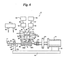
- Figure 6 shows another approach in which the principles of the present invention may be practiced to form prosthesis 9 having a desired level of inner porosity.
- this approach is similar to that of Figures 1-4, except that fibrous components 34 and 35 are co-sprayed around mandrel 12 bearing water soluble coating 36. The presence of this coating makes it significantly easier to remove prosthesis 9 from mandrel 12. Coating 36 also may further help to prevent water insoluble fibrous component 34 from coalescing on mandrel 12 after spraying to some degree.
- the water soluble material incorporated into coating 36 may be any water soluble, organic, solid or semisolid material under the conditions at which electrostatic spraying is carried out.
- such water soluble material may further comprise properties effective to help reduce the tendency of portions of fiber component 34 to coalesce around mandrel 12.
- Such materials include one or more oligomeric or polymeric materials selected from polyethylene glycols (PEG) preferably having a weight average molecular weight in the range from 1000 to about 10,000; polyvinyl alcohol; polyacrylamide; poly(methylvinyl ether); polyacrylic acid; poly(vinylpyridine); esters of poly(meth)acrylic acid wherein the ester group may be represented by the formula -OR in which the R moiety is sufficiently small (e.g., methyl or ethyl or other C 1 or C 2 type of moiety) so that the polymer is water soluble; similar esters of polyvinyl alcohol; combinations of these, and the like.
- the water soluble material is PEG, more preferably PEG having a weight average molecular weight of about 8000.
- coating 36 may be heated prior to electrostatic spraying operations.
- coating 36 may be heated to a temperature close to, more preferably slightly above, the glass transition temperature of the material(s) constituting coating 36 so that the material of coating 36 at least partially melts to provide a smooth, even, uniform coatable surface upon which to form prosthesis 9.
- coating 36 comprises PEG having a weight average molecular weight of about 8000 (PEG 8000)
- a 250 Watt IR lamp can be placed about 190 mm away from mandrel 12 to accomplish heating.
- Coating 36 may be applied onto mandrel 12 in any convenient form such as a melt, a solution, or a dispersion, as desired.
- the particular technique used to apply coating 36 is not critical and any suitable coating technique may be used, including brushing, dip coating, spraying, and the like.
- the solution or dispersion preferably contains a sufficient amount of solvent so that the solution or dispersion has a viscosity suitable for the application technique being used. Most typically, such a solution or dispersion may comprise 20 to 150 parts by weight of elutable material per about 80 parts by weight of solvent.
- one preferred solution for forming coating 36 may comprise about 120 parts by weight of PEG 8000 and about 80 parts by weight of solvent.
- a wide range of solvents may beneficially be incorporated into the solution or dispersion that is used to form coating 36. These include, for example, dichloromethane, water, alcohols, combinations of these, and the like, of which water, alcohols or combination of these are preferred.
- coating 36 may be dried before carrying out electrostatic spraying operations. Once coating 36 is formed on mandrel 12, electrostatic spraying operations may be carried out as described above with respect to Figure 1.
- the inside diameter of a prosthesis was estimated from measurements of the outside diameter of the mandrel that were made using a calibrated digital caliper.
- the wall thickness of a prosthesis was determined using an OPTIMUS Optical Image Analyzer with a NIKON MIIA 11122 Microphot F/X magnification of X150 and a calibrated graticule.
- a cross-section of a prosthesis was placed on a microscope slide using reflected light. The top surface of the prosthesis cross-section was brought into focus.
- Six wall thickness measurements in micrometers were taken at approximately equal distances around the circumference of the prosthesis. An average and a standard deviation were recorded for each prosthesis tested.
- a prosthesis of the present invention exhibits porosity on at least the inner wall surface of the prosthesis, more preferably on both the inner and outer wall surfaces of the prosthesis. More preferably, the prosthesis further exhibits a sufficient level of porosity on at least the inner wall surface to benefit from cellular ingrowth and fixation of the prosthesis upon implantation.
- the level of porosity will depend upon the particular application in which prosthesis 9 will be used. Generally, a beneficial amount of porosity may be in the range from 5% to 95%.
- a vascular prosthesis preferably has a porosity of 60% to 85%, more preferably 70% to 80%.
- a prosthesis to be used for drug delivery applications may have higher porosity levels, e.g., 80% to 95%.
- the outside diameter of a prosthesis was determined at several elongations. Two dots, two centimeters apart, were marked in the middle of a prosthesis. The outside diameter between the two dots was measured with a meterstick placed perpendicular to the prosthesis and was recorded as the outside diameter at 0% elongation.
- the prosthesis was then stretched to a pre-determined elongation, and an outside diameter between the two dots was again recorded.
- the pre-determined elongation was obtained by placing two dots on a piece of paper for the two dots on the prosthesis to be matched against. For example, for 100% elongation, the two dots on the prosthesis originally 2 cm apart would be stretched to match two dots on the paper that were 4 cm apart. Outside diameters were obtained at elongations of 0, 10, 25, 50, 100 and 150%.
- the longitudinal force to break and percent strain at break were determined for a prosthesis using an Instron tester with a 50 lb. (22.65 kg) tensile load cell. Pneumatic-operated grips with rubber facings were used to hold the sample (10 ⁇ 0. 1 cm long), with a grip separation of 50 ⁇ 1 mm. A crosshead speed of 100 ⁇ 1 mm/minute was used to raise the upper jaw until the prosthesis specimen failed. The maximum force in kilograms and the force in kilograms per thickness to break the prosthesis were recorded, along with % strain at break.
- the radial force at break and the deflection at break were determined for a prosthesis using an Instron tester with a 50 lb. (22.65 kg) tensile load cell. Split bar jaws were used to hold a prosthesis sample (1.27 cm long). A crosshead speed of 50 ⁇ 1 mm/minute was used until the prosthesis specimen failed. The maximum force in kilograms/cm 2 to break the prosthesis was recorded, along with the deflection at break.
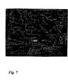
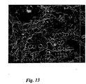
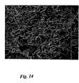
- the inner and outer surfaces of a prosthesis were analyzed using scanning electron microscopy (SEM) using a JEOL JSM 6400 scanning electron microscope. Specifically, a small piece of prosthesis (approximately 1 cm) was cut open. A small portion of this section of prosthesis was then affixed to an SEM mount using two sided tape. The sample was then gold-coated prior to analysis. SEM photomicrographs were obtained of the surfaces at two magnifications, 30 and 100X.
- SEM scanning electron microscopy
- Fiber forming composition 32 comprised the 40016 grade silicone manufactured by Applied Silicone Technology. The silicone was received as a 29% solids solution in trichloroethane. To provide fiber forming composition 32, this silicone solution was dried to 80% solids to remove most of the trichloroethane (TCE) and then diluted with dichloromethane (DCM) to obtain a 20% solids solution.
- Fiber forming composition 33 comprised a 60% solids PEG 8000 (i.e., a PEG with a weight average molecular weight of 8000, which is a solid under the processing conditions when neat) solution in DCM.
- a comparative prostheses was prepared in which a PEG (PEG 600) having a molecular weight of 600 (a liquid under the processing conditions) was substituted for the PEG 8000.
- PEG 600 PEG 600
- Each of cylinders 42 and 43 used in this example and all the other examples was in the form of a 10 cc syringe equipped with a 25 gauge shortened needle.
- the syringes were centrifuged prior to forming the prostheses to remove air bubbles which might have developed when the syringes were filled.
- the solutions were pumped out of the syringes at differing flow rates as shown in Table I.
- Table II The process conditions at which the prostheses were produced are summarized in Table II.
- comparative sample 99A was unsatisfactory. Droplets of this liquid PEG were attracted to the mandrel by electrostatic action, but these were then ejected from the rotating mandrel by centrifugal forces. Comparative prosthesis sample # 99-A even had fibers extending out from the surface. These exterior fibers were gently pressed in by rolling the prosthesis on a clean, flat surface.
- Example 1 The procedure of Example 1 was repeated except that the processing conditions of Table III and IV were used. A total of four prosthesis samples of the present invention were made. The prosthesis samples produced were tested for dimensions, porosity, mechanical properties, and examined under SEM.
- Prosthesis Sample Identification Prosthesis Sample Identification PEG Flow Rate (cc/min) Silicone Flow Rate (cc/min) PEG/Silicone Ratio Spinning Time (Min) 103-C 0.05 0.5 0.2:1 35 104-A 0.1 0.4 0.5:1 45 104-D 0.15 0.3 1:1 65 104-F 0.2 0.2 2:1 95 Process Conditions for Prosthesis Production PEG Solids Content (%) 40 Silicone Solids Content (%) 20 Spinneret-Mandrel Distance (mm) 150 Electrostatic Voltage (KV) 45.5 Mandrel Rotational Speed (rpm) 1500 Mandrel Transverse Speed (cm/min) 401 Needle Size (gauge) 25 Needle Length (mm) 3.0
- the prosthesis obtained using the lowest PEG/silicone weight ratio i.e., 0.2:1 exhibited the highest load at break and deflection at break.
- Table VII The data of Table VII was normalized and converted to percentages, with the initial diameter being the reference. The normalized data is shown in Table VIII, below. Outside Diameter (%) vs. % Elongation Sample Prosthesis Identification OUTSIDE DIAMETER (%) % Elongation 0 10 25 50 100 150 103-C 100 93.3 93.3 86.7 73.3 66.7 104-A 100 100 100 93.3 86.7 80.0 104-D 100 100 94.1 88.2 82.4 76.5 104-F 100 100 100 100 100 94.1 88.2
- Prosthesis Sample Identification as per Preheating, Drying and Curing Conditions
- Prosthesis Sample Identification Mandrel Preheating Drying Conditions
- Process Conditions for Prosthesis Production Spinneret-Mandrel Distance (mm) 150
- a silicone elastomer (MED-4070 grade for restricted applications) from Nusil Silicone Technology was selected for its combination of high hardness/durometer value (70 shore A) and high viscosity.
Landscapes
- Health & Medical Sciences (AREA)
- Engineering & Computer Science (AREA)
- Biomedical Technology (AREA)
- Pulmonology (AREA)
- Vascular Medicine (AREA)
- Cardiology (AREA)
- Oral & Maxillofacial Surgery (AREA)
- Transplantation (AREA)
- Veterinary Medicine (AREA)
- Heart & Thoracic Surgery (AREA)
- Gastroenterology & Hepatology (AREA)
- Life Sciences & Earth Sciences (AREA)
- Animal Behavior & Ethology (AREA)
- General Health & Medical Sciences (AREA)
- Public Health (AREA)
- Mechanical Engineering (AREA)
- Prostheses (AREA)
- Materials For Medical Uses (AREA)
- Application Of Or Painting With Fluid Materials (AREA)
Claims (25)
- Procédé de fabrication d'une prothèse synthétique tubulaire poreuse (9), comprenant les étapes :(a) de mise à disposition d'une précurseur de prothèse par pulvérisation électrostatique conjointe d'un composant fibreux polymère insoluble dans l'eau (34) et d'un composant fibreux hydrosoluble (35) sur un moule pour former un précurseur de prothèse ;(b) d'élution d'au moins une portion du composant fibreux hydrosoluble (35) provenant du précurseur par lavage du précurseur de prothèse tubulaire à l'aide d'un éluant.
- Procédé selon la revendication 1, dans lequel le moule est un mandrin rotatif (12).
- Procédé selon la revendication 1, dans lequel l'éluant est l'eau.
- Procédé selon la revendication 1, dans lequel le précurseur de prothèse est tubulaire et dans lequel l'étape (b) comprend l'élimination du composant fibreux hydrosoluble (35) du précurseur de telle manière que la prothèse (9) ait une porosité dans le domaine allant de 5% à 95%.
- Procédé selon la revendication 4, dans lequel la prothèse (9) a une porosité allant de 60% à 95%.
- Procédé selon la revendication 5, dans lequel la prothèse (9) a une porosité allant de 70% à 80%.
- Procédé selon la revendication 1, dans lequel le moule de prothèse est un mandrin rotatif (12), et dans lequel les composants fibreux insolubles dans l'eau et solubles dans l'eau (34, 35) sont pulvérisés conjointement par voie électrostatique sur le mandrin rotatif (12) à partir d'un premier et d'un deuxième orifice respectivement, et dans lequel le premier et le deuxième orifices sont forcés d'opérer une translation axiale en aller-retour par rapport au mandrin (12), de manière à ce que les composants fibreux (34, 35) recouvrent le mandrin (12) d'un revêtement pour former ledit précurseur.
- Procédé selon la revendication 7, dans lequel l'étape de pulvérisation conjointe comprend les étapes :(i) d'extrusion d'une première composition (32) comprenant une résine de silicone insoluble dans l'eau à travers le premier orifice, pour former le composant fibreux insoluble dans l'eau (34) ; et(ii) d'extrusion d'une deuxième composition (33) comprenant un polyéthylèneglycol hydrosoluble à travers le deuxième orifice, pour former le composant fibreux hydrosoluble (35).
- Procédé selon la revendication 8, dans lequel le polyéthylèneglycol a un poids moléculaire moyen au poids d'au moins 1 000.
- Procédé selon la revendication 9, dans lequel le polyéthylèneglycol a un poids moléculaire moyen au poids dans le domaine allant de 1 000 à 15 000.
- Procédé selon la revendication 8, dans lequel la première composition (32) comprend en outre un solvant dans lequel la résine de silicone est substantiellement complètement soluble, ledit solvant comprenant un premier et un deuxième composant de solvant, dans lequel le premier composant de solvant a un point d'ébullition d'au moins 10°C supérieur à celui du deuxième composant de solvant.
- Procédé selon la revendication 11, dans lequel le premier composant de solvant a un point d'ébullition supérieur d'au moins 25°C à celui du deuxième composant de solvant.
- Procédé selon la revendication 11, dans lequel le rapport pondéral du deuxième composant de solvant au premier composant de solvant est dans le domaine allant d'environ 2:1 à 10:1.
- Procédé selon la revendication 11, dans lequel le solvant comprend un solvant d'alcane halogéné sélectionné parmi un trihaloéthane, un dihaloéthane, un trihalométhane, un dihalométhane ou des combinaisons de ces derniers.
- Procédé selon la revendication 14, dans lequel le solvant comprend de 1 à 20 parts en poids de dichlorométhane et de 1 à 20 parts en poids de trichloroéthane.
- Procédé selon la revendication 1, dans lequel le rapport pondéral du composant fibreux insoluble dans l'eau au composant fibreux hydrosoluble est dans le domaine allant d'environ 1:10 à environ 5:1.
- Procédé selon la revendication 16, dans lequel le rapport pondéral du composant fibreux insoluble dans l'eau (34) au composant fibreux hydrosoluble (35) est dans le domaine allant d'environ 1:3 à environ 1:2.
- Procédé selon la revendication 1, dans lequel l'étape de pulvérisation conjointe comprend la pulvérisation conjointe tout à la fois des composants fibreux insolubles dans l'eau et hydrosolubles (34, 35) sur le moule pour accumuler la portion interne du précurseur de prothèse tubulaire et dans lequel le procédé comprend en outre les étapes :(i) d'arrêt de la pulvérisation du composant fibreux hydrosoluble (35) sur le moule lorsque ladite portion interne est formée ; et(ii) après arrêt de la pulvérisation du composant fibreux hydrosoluble (35) sur le moule, de poursuite de la pulvérisation du composant fibreux insoluble dans l'eau sur le moule jusqu'à la formation dudit précurseur de prothèse tubulaire.
- Procédé selon la revendication 2, comprenant, en outre, l'étape, précédant la pulvérisation conjointe desdits composants fibreux (34, 35) sur le moule, de revêtement du moule à l'aide d'un revêtement comprenant du polyéthylèneglycol.
- Prothèse (9) comprenant un corps tubulaire ayant une surface de paroi interne et une surface de paroi externe, ledit corps comprenant une structure polymère élastomère fibreuse, caractérisée en ce que ledit corps comprend des vides façonnés fibreux.
- Prothèse selon la revendication 20, dans laquelle la structure polymère élastomère comprend une résine de silicone.
- Prothèse (9) selon la revendication 20, dans laquelle au moins une portion des vides sont à proximité de la surface de paroi interne du corps tubulaire.
- Procédé de fabrication d'un précurseur de prothèse tubulaire, comprenant un composant fibreux hydrosoluble (35) et un composant fibreux polymère insoluble dans l'eau (34), comprenant l'étape de pulvérisation conjointe par voie électrostatique d'un composant fibreux polymère insoluble dans l'eau (34) et d'un composant fibreux hydrosoluble (35) sur une moule pour former le précurseur de prothèse tubulaire.
- Précurseur de prothèse, comprenant un corps tubulaire comprenant un composant fibreux polymère insoluble dans l'eau (34) et un composant fibreux hydrosoluble (35).
- Précurseur de prothèse selon la revendication 24, dans lequel le composant fibreux insoluble dans l'eau (34) comprend une résine de silicone élastomère et dans lequel le composant fibreux hydrosoluble (35) comprend un polyéthylèneglycol ayant un poids moléculaire moyen au poids allant de 1 000 à 15 000.
Applications Claiming Priority (2)
| Application Number | Priority Date | Filing Date | Title |
|---|---|---|---|
| US4809197P | 1997-05-30 | 1997-05-30 | |
| US48091P | 1997-05-30 |
Publications (3)
| Publication Number | Publication Date |
|---|---|
| EP0914918A2 EP0914918A2 (fr) | 1999-05-12 |
| EP0914918A3 EP0914918A3 (fr) | 2001-02-14 |
| EP0914918B1 true EP0914918B1 (fr) | 2004-03-03 |
Family
ID=21952684
Family Applications (1)
| Application Number | Title | Priority Date | Filing Date |
|---|---|---|---|
| EP98303484A Expired - Lifetime EP0914918B1 (fr) | 1997-05-30 | 1998-05-05 | Prothèse tubulaire poreuse et méthode pour sa fabrication par co-aspersion sur un mandrin en rotation de composés solubles et non-solubles à l'eau |
Country Status (5)
| Country | Link |
|---|---|
| US (1) | US6056993A (fr) |
| EP (1) | EP0914918B1 (fr) |
| JP (1) | JPH1176278A (fr) |
| CA (1) | CA2236960A1 (fr) |
| DE (1) | DE69822072T2 (fr) |
Cited By (1)
| Publication number | Priority date | Publication date | Assignee | Title |
|---|---|---|---|---|
| US9549831B2 (en) | 2002-02-07 | 2017-01-24 | Dsm Ip Assets B.V. | Apparatus and methods for conduits and materials |
Families Citing this family (281)
| Publication number | Priority date | Publication date | Assignee | Title |
|---|---|---|---|---|
| US6240616B1 (en) | 1997-04-15 | 2001-06-05 | Advanced Cardiovascular Systems, Inc. | Method of manufacturing a medicated porous metal prosthesis |
| US8172897B2 (en) | 1997-04-15 | 2012-05-08 | Advanced Cardiovascular Systems, Inc. | Polymer and metal composite implantable medical devices |
| US10028851B2 (en) | 1997-04-15 | 2018-07-24 | Advanced Cardiovascular Systems, Inc. | Coatings for controlling erosion of a substrate of an implantable medical device |
| US6540780B1 (en) * | 1998-11-23 | 2003-04-01 | Medtronic, Inc. | Porous synthetic vascular grafts with oriented ingrowth channels |
| US6730349B2 (en) * | 1999-04-19 | 2004-05-04 | Scimed Life Systems, Inc. | Mechanical and acoustical suspension coating of medical implants |
| US6702848B1 (en) | 1999-07-20 | 2004-03-09 | Peter Paul Zilla | Foam-type vascular prosthesis with well-defined anclio-permissive open porosity |
| US6759054B2 (en) | 1999-09-03 | 2004-07-06 | Advanced Cardiovascular Systems, Inc. | Ethylene vinyl alcohol composition and coating |
| US6790228B2 (en) * | 1999-12-23 | 2004-09-14 | Advanced Cardiovascular Systems, Inc. | Coating for implantable devices and a method of forming the same |
| US20040029952A1 (en) * | 1999-09-03 | 2004-02-12 | Yung-Ming Chen | Ethylene vinyl alcohol composition and coating |
| US7682647B2 (en) * | 1999-09-03 | 2010-03-23 | Advanced Cardiovascular Systems, Inc. | Thermal treatment of a drug eluting implantable medical device |
| US7807211B2 (en) | 1999-09-03 | 2010-10-05 | Advanced Cardiovascular Systems, Inc. | Thermal treatment of an implantable medical device |
| US20070032853A1 (en) | 2002-03-27 | 2007-02-08 | Hossainy Syed F | 40-O-(2-hydroxy)ethyl-rapamycin coated stent |
| US6908624B2 (en) * | 1999-12-23 | 2005-06-21 | Advanced Cardiovascular Systems, Inc. | Coating for implantable devices and a method of forming the same |
| US6527801B1 (en) * | 2000-04-13 | 2003-03-04 | Advanced Cardiovascular Systems, Inc. | Biodegradable drug delivery material for stent |
| US8109994B2 (en) | 2003-01-10 | 2012-02-07 | Abbott Cardiovascular Systems, Inc. | Biodegradable drug delivery material for stent |
| US7875283B2 (en) * | 2000-04-13 | 2011-01-25 | Advanced Cardiovascular Systems, Inc. | Biodegradable polymers for use with implantable medical devices |
| CA2409093C (fr) | 2000-05-16 | 2009-07-21 | Regents Of The University Of Minnesota | Generation de particules a haut debit massique faisant appel a une pulverisation a buses multiples |
| US20040211362A1 (en) * | 2000-05-31 | 2004-10-28 | Daniel Castro | System for coating a stent |
| WO2001091918A1 (fr) * | 2000-05-31 | 2001-12-06 | Advanced Cardiovascular Systems, Inc. | Appareil et procede permettant de former un revetement sur une surface d'une prothese |
| US7682648B1 (en) | 2000-05-31 | 2010-03-23 | Advanced Cardiovascular Systems, Inc. | Methods for forming polymeric coatings on stents |
| US6395326B1 (en) * | 2000-05-31 | 2002-05-28 | Advanced Cardiovascular Systems, Inc. | Apparatus and method for depositing a coating onto a surface of a prosthesis |
| US6723373B1 (en) * | 2000-06-16 | 2004-04-20 | Cordis Corporation | Device and process for coating stents |
| US6555157B1 (en) * | 2000-07-25 | 2003-04-29 | Advanced Cardiovascular Systems, Inc. | Method for coating an implantable device and system for performing the method |
| US6451373B1 (en) * | 2000-08-04 | 2002-09-17 | Advanced Cardiovascular Systems, Inc. | Method of forming a therapeutic coating onto a surface of an implantable prosthesis |
| US6953560B1 (en) | 2000-09-28 | 2005-10-11 | Advanced Cardiovascular Systems, Inc. | Barriers for polymer-coated implantable medical devices and methods for making the same |
| US6783793B1 (en) * | 2000-10-26 | 2004-08-31 | Advanced Cardiovascular Systems, Inc. | Selective coating of medical devices |
| US7807210B1 (en) | 2000-10-31 | 2010-10-05 | Advanced Cardiovascular Systems, Inc. | Hemocompatible polymers on hydrophobic porous polymers |
| US6824559B2 (en) | 2000-12-22 | 2004-11-30 | Advanced Cardiovascular Systems, Inc. | Ethylene-carboxyl copolymers as drug delivery matrices |
| US6663662B2 (en) * | 2000-12-28 | 2003-12-16 | Advanced Cardiovascular Systems, Inc. | Diffusion barrier layer for implantable devices |
| US7504125B1 (en) * | 2001-04-27 | 2009-03-17 | Advanced Cardiovascular Systems, Inc. | System and method for coating implantable devices |
| US6712845B2 (en) * | 2001-04-24 | 2004-03-30 | Advanced Cardiovascular Systems, Inc. | Coating for a stent and a method of forming the same |
| US6656506B1 (en) * | 2001-05-09 | 2003-12-02 | Advanced Cardiovascular Systems, Inc. | Microparticle coated medical device |
| WO2002090540A1 (fr) * | 2001-05-10 | 2002-11-14 | The Salk Institute For Biological Studies | Plantes insensibles a l'ethylene |
| US7247338B2 (en) * | 2001-05-16 | 2007-07-24 | Regents Of The University Of Minnesota | Coating medical devices |
| US6605154B1 (en) * | 2001-05-31 | 2003-08-12 | Advanced Cardiovascular Systems, Inc. | Stent mounting device |
| US6743462B1 (en) * | 2001-05-31 | 2004-06-01 | Advanced Cardiovascular Systems, Inc. | Apparatus and method for coating implantable devices |
| US6695920B1 (en) | 2001-06-27 | 2004-02-24 | Advanced Cardiovascular Systems, Inc. | Mandrel for supporting a stent and a method of using the mandrel to coat a stent |
| US7175873B1 (en) | 2001-06-27 | 2007-02-13 | Advanced Cardiovascular Systems, Inc. | Rate limiting barriers for implantable devices and methods for fabrication thereof |
| US7247313B2 (en) * | 2001-06-27 | 2007-07-24 | Advanced Cardiovascular Systems, Inc. | Polyacrylates coatings for implantable medical devices |
| US8741378B1 (en) | 2001-06-27 | 2014-06-03 | Advanced Cardiovascular Systems, Inc. | Methods of coating an implantable device |
| US6673154B1 (en) * | 2001-06-28 | 2004-01-06 | Advanced Cardiovascular Systems, Inc. | Stent mounting device to coat a stent |
| US6527863B1 (en) | 2001-06-29 | 2003-03-04 | Advanced Cardiovascular Systems, Inc. | Support device for a stent and a method of using the same to coat a stent |
| US6682771B2 (en) | 2001-07-02 | 2004-01-27 | Scimed Life Systems, Inc. | Coating dispensing system and method using a solenoid head for coating medical devices |
| US7246321B2 (en) * | 2001-07-13 | 2007-07-17 | Anoto Ab | Editing data |
| EP1414369A2 (fr) * | 2001-07-27 | 2004-05-06 | Medtronic, Inc. | Prothese vasculaire poreuse renforcee par un tissu adventice |
| US7682669B1 (en) | 2001-07-30 | 2010-03-23 | Advanced Cardiovascular Systems, Inc. | Methods for covalently immobilizing anti-thrombogenic material into a coating on a medical device |
| US8303651B1 (en) | 2001-09-07 | 2012-11-06 | Advanced Cardiovascular Systems, Inc. | Polymeric coating for reducing the rate of release of a therapeutic substance from a stent |
| US7285304B1 (en) | 2003-06-25 | 2007-10-23 | Advanced Cardiovascular Systems, Inc. | Fluid treatment of a polymeric coating on an implantable medical device |
| US7989018B2 (en) | 2001-09-17 | 2011-08-02 | Advanced Cardiovascular Systems, Inc. | Fluid treatment of a polymeric coating on an implantable medical device |
| US6669980B2 (en) * | 2001-09-18 | 2003-12-30 | Scimed Life Systems, Inc. | Method for spray-coating medical devices |
| US6863683B2 (en) | 2001-09-19 | 2005-03-08 | Abbott Laboratoris Vascular Entities Limited | Cold-molding process for loading a stent onto a stent delivery system |
| US7223282B1 (en) * | 2001-09-27 | 2007-05-29 | Advanced Cardiovascular Systems, Inc. | Remote activation of an implantable device |
| US6753071B1 (en) | 2001-09-27 | 2004-06-22 | Advanced Cardiovascular Systems, Inc. | Rate-reducing membrane for release of an agent |
| US20030059520A1 (en) * | 2001-09-27 | 2003-03-27 | Yung-Ming Chen | Apparatus for regulating temperature of a composition and a method of coating implantable devices |
| US7585516B2 (en) * | 2001-11-12 | 2009-09-08 | Advanced Cardiovascular Systems, Inc. | Coatings for drug delivery devices |
| US7175874B1 (en) | 2001-11-30 | 2007-02-13 | Advanced Cardiovascular Systems, Inc. | Apparatus and method for coating implantable devices |
| US6709514B1 (en) * | 2001-12-28 | 2004-03-23 | Advanced Cardiovascular Systems, Inc. | Rotary coating apparatus for coating implantable medical devices |
| JP3993773B2 (ja) * | 2002-02-20 | 2007-10-17 | 株式会社日立製作所 | ストレージサブシステム、記憶制御装置及びデータコピー方法 |
| US7858143B2 (en) * | 2002-03-15 | 2010-12-28 | Abbott Cardiovascular System Inc. | Apparatus and method for coating stents |
| US7232490B1 (en) * | 2002-03-15 | 2007-06-19 | Advanced Cardiovascular Systems, Inc. | Apparatus and method for coating stents |
| US7919075B1 (en) | 2002-03-20 | 2011-04-05 | Advanced Cardiovascular Systems, Inc. | Coatings for implantable medical devices |
| US7022334B1 (en) * | 2002-03-20 | 2006-04-04 | Advanced Cardiovascular Systems, Inc. | Therapeutic composition and a method of coating implantable medical devices |
| US7056523B1 (en) | 2002-06-21 | 2006-06-06 | Advanced Cardiovascular Systems, Inc. | Implantable medical devices incorporating chemically conjugated polymers and oligomers of L-arginine |
| US7794743B2 (en) | 2002-06-21 | 2010-09-14 | Advanced Cardiovascular Systems, Inc. | Polycationic peptide coatings and methods of making the same |
| US7396539B1 (en) * | 2002-06-21 | 2008-07-08 | Advanced Cardiovascular Systems, Inc. | Stent coatings with engineered drug release rate |
| US7033602B1 (en) | 2002-06-21 | 2006-04-25 | Advanced Cardiovascular Systems, Inc. | Polycationic peptide coatings and methods of coating implantable medical devices |
| US8506617B1 (en) | 2002-06-21 | 2013-08-13 | Advanced Cardiovascular Systems, Inc. | Micronized peptide coated stent |
| US7217426B1 (en) | 2002-06-21 | 2007-05-15 | Advanced Cardiovascular Systems, Inc. | Coatings containing polycationic peptides for cardiovascular therapy |
| US7294329B1 (en) * | 2002-07-18 | 2007-11-13 | Advanced Cardiovascular Systems, Inc. | Poly(vinyl acetal) coatings for implantable medical devices |
| US7622146B2 (en) * | 2002-07-18 | 2009-11-24 | Advanced Cardiovascular Systems, Inc. | Rate limiting barriers for implantable devices and methods for fabrication thereof |
| US7363074B1 (en) * | 2002-08-20 | 2008-04-22 | Advanced Cardiovascular Systems, Inc. | Coatings comprising self-assembled molecular structures and a method of delivering a drug using the same |
| US20040054104A1 (en) * | 2002-09-05 | 2004-03-18 | Pacetti Stephen D. | Coatings for drug delivery devices comprising modified poly(ethylene-co-vinyl alcohol) |
| US7732535B2 (en) * | 2002-09-05 | 2010-06-08 | Advanced Cardiovascular Systems, Inc. | Coating for controlled release of drugs from implantable medical devices |
| US7201935B1 (en) | 2002-09-17 | 2007-04-10 | Advanced Cardiovascular Systems, Inc. | Plasma-generated coatings for medical devices and methods for fabricating thereof |
| US20040063805A1 (en) * | 2002-09-19 | 2004-04-01 | Pacetti Stephen D. | Coatings for implantable medical devices and methods for fabrication thereof |
| US7438722B1 (en) | 2002-09-20 | 2008-10-21 | Advanced Cardiovascular Systems, Inc. | Method for treatment of restenosis |
| US6818063B1 (en) | 2002-09-24 | 2004-11-16 | Advanced Cardiovascular Systems, Inc. | Stent mandrel fixture and method for minimizing coating defects |
| US7232573B1 (en) * | 2002-09-26 | 2007-06-19 | Advanced Cardiovascular Systems, Inc. | Stent coatings containing self-assembled monolayers |
| US7776381B1 (en) * | 2002-09-26 | 2010-08-17 | Advanced Cardiovascular Systems, Inc. | Stent mandrel fixture and method for reducing coating defects |
| US8202530B2 (en) * | 2002-09-27 | 2012-06-19 | Advanced Cardiovascular Systems, Inc. | Biocompatible coatings for stents |
| US7404979B1 (en) | 2002-09-30 | 2008-07-29 | Advanced Cardiovascular Systems Inc. | Spin coating apparatus and a method for coating implantable devices |
| US8337937B2 (en) * | 2002-09-30 | 2012-12-25 | Abbott Cardiovascular Systems Inc. | Stent spin coating method |
| US7335265B1 (en) * | 2002-10-08 | 2008-02-26 | Advanced Cardiovascular Systems Inc. | Apparatus and method for coating stents |
| US7087263B2 (en) * | 2002-10-09 | 2006-08-08 | Advanced Cardiovascular Systems, Inc. | Rare limiting barriers for implantable medical devices |
| PL377190A1 (pl) * | 2002-11-07 | 2006-01-23 | Abbott Laboratories | Proteza z wieloma lekami w postaci indywidualnych niezmieszanych kropli |
| US6896965B1 (en) | 2002-11-12 | 2005-05-24 | Advanced Cardiovascular Systems, Inc. | Rate limiting barriers for implantable devices |
| US8034361B2 (en) * | 2002-11-12 | 2011-10-11 | Advanced Cardiovascular Systems, Inc. | Stent coatings incorporating nanoparticles |
| US7022372B1 (en) | 2002-11-12 | 2006-04-04 | Advanced Cardiovascular Systems, Inc. | Compositions for coating implantable medical devices |
| US7416609B1 (en) | 2002-11-25 | 2008-08-26 | Advanced Cardiovascular Systems, Inc. | Support assembly for a stent |
| US6982004B1 (en) * | 2002-11-26 | 2006-01-03 | Advanced Cardiovascular Systems, Inc. | Electrostatic loading of drugs on implantable medical devices |
| US7211150B1 (en) * | 2002-12-09 | 2007-05-01 | Advanced Cardiovascular Systems, Inc. | Apparatus and method for coating and drying multiple stents |
| US7776926B1 (en) | 2002-12-11 | 2010-08-17 | Advanced Cardiovascular Systems, Inc. | Biocompatible coating for implantable medical devices |
| US7758880B2 (en) * | 2002-12-11 | 2010-07-20 | Advanced Cardiovascular Systems, Inc. | Biocompatible polyacrylate compositions for medical applications |
| US7074276B1 (en) | 2002-12-12 | 2006-07-11 | Advanced Cardiovascular Systems, Inc. | Clamp mandrel fixture and a method of using the same to minimize coating defects |
| US20060002968A1 (en) * | 2004-06-30 | 2006-01-05 | Gordon Stewart | Anti-proliferative and anti-inflammatory agent combination for treatment of vascular disorders |
| US7758881B2 (en) | 2004-06-30 | 2010-07-20 | Advanced Cardiovascular Systems, Inc. | Anti-proliferative and anti-inflammatory agent combination for treatment of vascular disorders with an implantable medical device |
| US8435550B2 (en) | 2002-12-16 | 2013-05-07 | Abbot Cardiovascular Systems Inc. | Anti-proliferative and anti-inflammatory agent combination for treatment of vascular disorders with an implantable medical device |
| US7338557B1 (en) | 2002-12-17 | 2008-03-04 | Advanced Cardiovascular Systems, Inc. | Nozzle for use in coating a stent |
| US7628859B1 (en) * | 2002-12-27 | 2009-12-08 | Advanced Cardiovascular Systems, Inc. | Mounting assembly for a stent and a method of using the same to coat a stent |
| US20040126405A1 (en) * | 2002-12-30 | 2004-07-01 | Scimed Life Systems, Inc. | Engineered scaffolds for promoting growth of cells |
| US7083697B2 (en) * | 2002-12-30 | 2006-08-01 | Boston Scientific Scimed, Inc. | Porous spun polymeric structures and method of making same |
| US7087115B1 (en) * | 2003-02-13 | 2006-08-08 | Advanced Cardiovascular Systems, Inc. | Nozzle and method for use in coating a stent |
| US7354480B1 (en) * | 2003-02-26 | 2008-04-08 | Advanced Cardiovascular Systems, Inc. | Stent mandrel fixture and system for reducing coating defects |
| US6926919B1 (en) | 2003-02-26 | 2005-08-09 | Advanced Cardiovascular Systems, Inc. | Method for fabricating a coating for a medical device |
| US7255891B1 (en) * | 2003-02-26 | 2007-08-14 | Advanced Cardiovascular Systems, Inc. | Method for coating implantable medical devices |
| US7563483B2 (en) * | 2003-02-26 | 2009-07-21 | Advanced Cardiovascular Systems Inc. | Methods for fabricating a coating for implantable medical devices |
| US8715771B2 (en) * | 2003-02-26 | 2014-05-06 | Abbott Cardiovascular Systems Inc. | Coated stent and method of making the same |
| US7288609B1 (en) | 2003-03-04 | 2007-10-30 | Advanced Cardiovascular Systems, Inc. | Coatings for drug delivery devices based on poly (orthoesters) |
| US7563454B1 (en) * | 2003-05-01 | 2009-07-21 | Advanced Cardiovascular Systems, Inc. | Coatings for implantable medical devices |
| US8791171B2 (en) * | 2003-05-01 | 2014-07-29 | Abbott Cardiovascular Systems Inc. | Biodegradable coatings for implantable medical devices |
| US7279174B2 (en) | 2003-05-08 | 2007-10-09 | Advanced Cardiovascular Systems, Inc. | Stent coatings comprising hydrophilic additives |
| US7323209B1 (en) | 2003-05-15 | 2008-01-29 | Advanced Cardiovascular Systems, Inc. | Apparatus and method for coating stents |
| US20040247775A1 (en) * | 2003-06-06 | 2004-12-09 | Boulais Dennis R. | Positive displacement coating deposition apparatus and method |
| US7186789B2 (en) * | 2003-06-11 | 2007-03-06 | Advanced Cardiovascular Systems, Inc. | Bioabsorbable, biobeneficial polyester polymers for use in drug eluting stent coatings |
| US20050118344A1 (en) | 2003-12-01 | 2005-06-02 | Pacetti Stephen D. | Temperature controlled crimping |
| US7645504B1 (en) | 2003-06-26 | 2010-01-12 | Advanced Cardiovascular Systems, Inc. | Coatings for implantable medical devices comprising hydrophobic and hydrophilic polymers |
| US7341630B1 (en) * | 2003-06-26 | 2008-03-11 | Advanced Cardiovascular Systems, Inc. | Stent coating system |
| US7875285B1 (en) | 2003-07-15 | 2011-01-25 | Advanced Cardiovascular Systems, Inc. | Medicated coatings for implantable medical devices having controlled rate of release |
| US20050021127A1 (en) * | 2003-07-21 | 2005-01-27 | Kawula Paul John | Porous glass fused onto stent for drug retention |
| US7056591B1 (en) * | 2003-07-30 | 2006-06-06 | Advanced Cardiovascular Systems, Inc. | Hydrophobic biologically absorbable coatings for drug delivery devices and methods for fabricating the same |
| US7169404B2 (en) * | 2003-07-30 | 2007-01-30 | Advanced Cardiovasular Systems, Inc. | Biologically absorbable coatings for implantable devices and methods for fabricating the same |
| US7645474B1 (en) | 2003-07-31 | 2010-01-12 | Advanced Cardiovascular Systems, Inc. | Method and system of purifying polymers for use with implantable medical devices |
| US7431959B1 (en) * | 2003-07-31 | 2008-10-07 | Advanced Cardiovascular Systems Inc. | Method and system for irradiation of a drug eluting implantable medical device |
| US7785512B1 (en) | 2003-07-31 | 2010-08-31 | Advanced Cardiovascular Systems, Inc. | Method and system of controlled temperature mixing and molding of polymers with active agents for implantable medical devices |
| US7441513B1 (en) | 2003-09-26 | 2008-10-28 | Advanced Cardiovascular Systems, Inc. | Plasma-generated coating apparatus for medical devices and a method of coating deposition |
| US7198675B2 (en) | 2003-09-30 | 2007-04-03 | Advanced Cardiovascular Systems | Stent mandrel fixture and method for selectively coating surfaces of a stent |
| US7318932B2 (en) * | 2003-09-30 | 2008-01-15 | Advanced Cardiovascular Systems, Inc. | Coatings for drug delivery devices comprising hydrolitically stable adducts of poly(ethylene-co-vinyl alcohol) and methods for fabricating the same |
| US7704544B2 (en) * | 2003-10-07 | 2010-04-27 | Advanced Cardiovascular Systems, Inc. | System and method for coating a tubular implantable medical device |
| US7329413B1 (en) * | 2003-11-06 | 2008-02-12 | Advanced Cardiovascular Systems, Inc. | Coatings for drug delivery devices having gradient of hydration and methods for fabricating thereof |
| US7261946B2 (en) * | 2003-11-14 | 2007-08-28 | Advanced Cardiovascular Systems, Inc. | Block copolymers of acrylates and methacrylates with fluoroalkenes |
| US9114198B2 (en) | 2003-11-19 | 2015-08-25 | Advanced Cardiovascular Systems, Inc. | Biologically beneficial coatings for implantable devices containing fluorinated polymers and methods for fabricating the same |
| US8192752B2 (en) | 2003-11-21 | 2012-06-05 | Advanced Cardiovascular Systems, Inc. | Coatings for implantable devices including biologically erodable polyesters and methods for fabricating the same |
| US7560492B1 (en) | 2003-11-25 | 2009-07-14 | Advanced Cardiovascular Systems, Inc. | Polysulfone block copolymers as drug-eluting coating material |
| US7807722B2 (en) * | 2003-11-26 | 2010-10-05 | Advanced Cardiovascular Systems, Inc. | Biobeneficial coating compositions and methods of making and using thereof |
| US7220816B2 (en) | 2003-12-16 | 2007-05-22 | Advanced Cardiovascular Systems, Inc. | Biologically absorbable coatings for implantable devices based on poly(ester amides) and methods for fabricating the same |
| US7435788B2 (en) | 2003-12-19 | 2008-10-14 | Advanced Cardiovascular Systems, Inc. | Biobeneficial polyamide/polyethylene glycol polymers for use with drug eluting stents |
| US8309112B2 (en) * | 2003-12-24 | 2012-11-13 | Advanced Cardiovascular Systems, Inc. | Coatings for implantable medical devices comprising hydrophilic substances and methods for fabricating the same |
| US8042485B1 (en) | 2003-12-30 | 2011-10-25 | Advanced Cardiovascular Systems, Inc. | Stent mandrel fixture and method for coating stents |
| US8685431B2 (en) | 2004-03-16 | 2014-04-01 | Advanced Cardiovascular Systems, Inc. | Biologically absorbable coatings for implantable devices based on copolymers having ester bonds and methods for fabricating the same |
| US8349388B1 (en) | 2004-03-18 | 2013-01-08 | Advanced Cardiovascular Systems, Inc. | Method of coating a stent |
| US20050208093A1 (en) * | 2004-03-22 | 2005-09-22 | Thierry Glauser | Phosphoryl choline coating compositions |
| US8551512B2 (en) | 2004-03-22 | 2013-10-08 | Advanced Cardiovascular Systems, Inc. | Polyethylene glycol/poly(butylene terephthalate) copolymer coated devices including EVEROLIMUS |
| US20050214339A1 (en) * | 2004-03-29 | 2005-09-29 | Yiwen Tang | Biologically degradable compositions for medical applications |
| US8778014B1 (en) | 2004-03-31 | 2014-07-15 | Advanced Cardiovascular Systems, Inc. | Coatings for preventing balloon damage to polymer coated stents |
| US7553377B1 (en) * | 2004-04-27 | 2009-06-30 | Advanced Cardiovascular Systems, Inc. | Apparatus and method for electrostatic coating of an abluminal stent surface |
| US8293890B2 (en) | 2004-04-30 | 2012-10-23 | Advanced Cardiovascular Systems, Inc. | Hyaluronic acid based copolymers |
| US7820732B2 (en) * | 2004-04-30 | 2010-10-26 | Advanced Cardiovascular Systems, Inc. | Methods for modulating thermal and mechanical properties of coatings on implantable devices |
| US8623067B2 (en) | 2004-05-25 | 2014-01-07 | Covidien Lp | Methods and apparatus for luminal stenting |
| US8617234B2 (en) | 2004-05-25 | 2013-12-31 | Covidien Lp | Flexible vascular occluding device |
| US20060206200A1 (en) | 2004-05-25 | 2006-09-14 | Chestnut Medical Technologies, Inc. | Flexible vascular occluding device |
| US8267985B2 (en) | 2005-05-25 | 2012-09-18 | Tyco Healthcare Group Lp | System and method for delivering and deploying an occluding device within a vessel |
| AU2005247490B2 (en) | 2004-05-25 | 2011-05-19 | Covidien Lp | Flexible vascular occluding device |
| AU2010236494B2 (en) | 2004-05-25 | 2013-05-30 | Covidien Lp | Vascular stenting for aneurysms |
| US9561309B2 (en) | 2004-05-27 | 2017-02-07 | Advanced Cardiovascular Systems, Inc. | Antifouling heparin coatings |
| US7563780B1 (en) | 2004-06-18 | 2009-07-21 | Advanced Cardiovascular Systems, Inc. | Heparin prodrugs and drug delivery stents formed therefrom |
| US8568469B1 (en) | 2004-06-28 | 2013-10-29 | Advanced Cardiovascular Systems, Inc. | Stent locking element and a method of securing a stent on a delivery system |
| US20050287184A1 (en) | 2004-06-29 | 2005-12-29 | Hossainy Syed F A | Drug-delivery stent formulations for restenosis and vulnerable plaque |
| US8241554B1 (en) | 2004-06-29 | 2012-08-14 | Advanced Cardiovascular Systems, Inc. | Method of forming a stent pattern on a tube |
| US8747879B2 (en) | 2006-04-28 | 2014-06-10 | Advanced Cardiovascular Systems, Inc. | Method of fabricating an implantable medical device to reduce chance of late inflammatory response |
| US7971333B2 (en) | 2006-05-30 | 2011-07-05 | Advanced Cardiovascular Systems, Inc. | Manufacturing process for polymetric stents |
| US7731890B2 (en) | 2006-06-15 | 2010-06-08 | Advanced Cardiovascular Systems, Inc. | Methods of fabricating stents with enhanced fracture toughness |
| US8778256B1 (en) | 2004-09-30 | 2014-07-15 | Advanced Cardiovascular Systems, Inc. | Deformation of a polymer tube in the fabrication of a medical article |
| US8747878B2 (en) | 2006-04-28 | 2014-06-10 | Advanced Cardiovascular Systems, Inc. | Method of fabricating an implantable medical device by controlling crystalline structure |
| US8357391B2 (en) | 2004-07-30 | 2013-01-22 | Advanced Cardiovascular Systems, Inc. | Coatings for implantable devices comprising poly (hydroxy-alkanoates) and diacid linkages |
| US7494665B1 (en) | 2004-07-30 | 2009-02-24 | Advanced Cardiovascular Systems, Inc. | Polymers containing siloxane monomers |
| US7758788B2 (en) * | 2004-08-13 | 2010-07-20 | Mentor Worldwide Llc | Spray method for forming shells for prostheses |
| US9283099B2 (en) | 2004-08-25 | 2016-03-15 | Advanced Cardiovascular Systems, Inc. | Stent-catheter assembly with a releasable connection for stent retention |
| US7648727B2 (en) | 2004-08-26 | 2010-01-19 | Advanced Cardiovascular Systems, Inc. | Methods for manufacturing a coated stent-balloon assembly |
| US7244443B2 (en) | 2004-08-31 | 2007-07-17 | Advanced Cardiovascular Systems, Inc. | Polymers of fluorinated monomers and hydrophilic monomers |
| US7229471B2 (en) | 2004-09-10 | 2007-06-12 | Advanced Cardiovascular Systems, Inc. | Compositions containing fast-leaching plasticizers for improved performance of medical devices |
| US8110211B2 (en) | 2004-09-22 | 2012-02-07 | Advanced Cardiovascular Systems, Inc. | Medicated coatings for implantable medical devices including polyacrylates |
| US8173062B1 (en) | 2004-09-30 | 2012-05-08 | Advanced Cardiovascular Systems, Inc. | Controlled deformation of a polymer tube in fabricating a medical article |
| US8043553B1 (en) | 2004-09-30 | 2011-10-25 | Advanced Cardiovascular Systems, Inc. | Controlled deformation of a polymer tube with a restraining surface in fabricating a medical article |
| US7875233B2 (en) | 2004-09-30 | 2011-01-25 | Advanced Cardiovascular Systems, Inc. | Method of fabricating a biaxially oriented implantable medical device |
| US8603634B2 (en) | 2004-10-27 | 2013-12-10 | Abbott Cardiovascular Systems Inc. | End-capped poly(ester amide) copolymers |
| US7390497B2 (en) | 2004-10-29 | 2008-06-24 | Advanced Cardiovascular Systems, Inc. | Poly(ester amide) filler blends for modulation of coating properties |
| US7214759B2 (en) * | 2004-11-24 | 2007-05-08 | Advanced Cardiovascular Systems, Inc. | Biologically absorbable coatings for implantable devices based on polyesters and methods for fabricating the same |
| US7588642B1 (en) * | 2004-11-29 | 2009-09-15 | Advanced Cardiovascular Systems, Inc. | Abluminal stent coating apparatus and method using a brush assembly |
| US8609123B2 (en) | 2004-11-29 | 2013-12-17 | Advanced Cardiovascular Systems, Inc. | Derivatized poly(ester amide) as a biobeneficial coating |
| US7892592B1 (en) | 2004-11-30 | 2011-02-22 | Advanced Cardiovascular Systems, Inc. | Coating abluminal surfaces of stents and other implantable medical devices |
| US7604818B2 (en) | 2004-12-22 | 2009-10-20 | Advanced Cardiovascular Systems, Inc. | Polymers of fluorinated monomers and hydrocarbon monomers |
| US7419504B2 (en) | 2004-12-27 | 2008-09-02 | Advanced Cardiovascular Systems, Inc. | Poly(ester amide) block copolymers |
| US8007775B2 (en) | 2004-12-30 | 2011-08-30 | Advanced Cardiovascular Systems, Inc. | Polymers containing poly(hydroxyalkanoates) and agents for use with medical articles and methods of fabricating the same |
| US7381048B2 (en) | 2005-04-12 | 2008-06-03 | Advanced Cardiovascular Systems, Inc. | Stents with profiles for gripping a balloon catheter and molds for fabricating stents |
| US7795467B1 (en) | 2005-04-26 | 2010-09-14 | Advanced Cardiovascular Systems, Inc. | Bioabsorbable, biobeneficial polyurethanes for use in medical devices |
| US8778375B2 (en) | 2005-04-29 | 2014-07-15 | Advanced Cardiovascular Systems, Inc. | Amorphous poly(D,L-lactide) coating |
| JP4945714B2 (ja) | 2005-05-25 | 2012-06-06 | タイコ ヘルスケア グループ リミテッド パートナーシップ | 管路内に閉塞装置を供給して展開するためのシステム及び方法 |
| US8273101B2 (en) | 2005-05-25 | 2012-09-25 | Tyco Healthcare Group Lp | System and method for delivering and deploying an occluding device within a vessel |
| US7823533B2 (en) | 2005-06-30 | 2010-11-02 | Advanced Cardiovascular Systems, Inc. | Stent fixture and method for reducing coating defects |
| US8021676B2 (en) | 2005-07-08 | 2011-09-20 | Advanced Cardiovascular Systems, Inc. | Functionalized chemically inert polymers for coatings |
| US7785647B2 (en) | 2005-07-25 | 2010-08-31 | Advanced Cardiovascular Systems, Inc. | Methods of providing antioxidants to a drug containing product |
| US7735449B1 (en) | 2005-07-28 | 2010-06-15 | Advanced Cardiovascular Systems, Inc. | Stent fixture having rounded support structures and method for use thereof |
| US7658880B2 (en) | 2005-07-29 | 2010-02-09 | Advanced Cardiovascular Systems, Inc. | Polymeric stent polishing method and apparatus |
| US9248034B2 (en) | 2005-08-23 | 2016-02-02 | Advanced Cardiovascular Systems, Inc. | Controlled disintegrating implantable medical devices |
| US7976891B1 (en) | 2005-12-16 | 2011-07-12 | Advanced Cardiovascular Systems, Inc. | Abluminal stent coating apparatus and method of using focused acoustic energy |
| US7867547B2 (en) | 2005-12-19 | 2011-01-11 | Advanced Cardiovascular Systems, Inc. | Selectively coating luminal surfaces of stents |
| US20070156230A1 (en) | 2006-01-04 | 2007-07-05 | Dugan Stephen R | Stents with radiopaque markers |
| US7951185B1 (en) | 2006-01-06 | 2011-05-31 | Advanced Cardiovascular Systems, Inc. | Delivery of a stent at an elevated temperature |
| US20070196428A1 (en) | 2006-02-17 | 2007-08-23 | Thierry Glauser | Nitric oxide generating medical devices |
| US8152833B2 (en) | 2006-02-22 | 2012-04-10 | Tyco Healthcare Group Lp | Embolic protection systems having radiopaque filter mesh |
| US7713637B2 (en) | 2006-03-03 | 2010-05-11 | Advanced Cardiovascular Systems, Inc. | Coating containing PEGylated hyaluronic acid and a PEGylated non-hyaluronic acid polymer |
| US7964210B2 (en) | 2006-03-31 | 2011-06-21 | Abbott Cardiovascular Systems Inc. | Degradable polymeric implantable medical devices with a continuous phase and discrete phase |
| DE102006051013A1 (de) * | 2006-05-02 | 2007-11-08 | Nonwotecc Medical Gmbh | Flächengefüge |
| US7985441B1 (en) | 2006-05-04 | 2011-07-26 | Yiwen Tang | Purification of polymers for coating applications |
| US8003156B2 (en) | 2006-05-04 | 2011-08-23 | Advanced Cardiovascular Systems, Inc. | Rotatable support elements for stents |
| US8304012B2 (en) | 2006-05-04 | 2012-11-06 | Advanced Cardiovascular Systems, Inc. | Method for drying a stent |
| US7761968B2 (en) | 2006-05-25 | 2010-07-27 | Advanced Cardiovascular Systems, Inc. | Method of crimping a polymeric stent |
| US7951194B2 (en) | 2006-05-26 | 2011-05-31 | Abbott Cardiovascular Sysetms Inc. | Bioabsorbable stent with radiopaque coating |
| US8752267B2 (en) | 2006-05-26 | 2014-06-17 | Abbott Cardiovascular Systems Inc. | Method of making stents with radiopaque markers |
| US7775178B2 (en) | 2006-05-26 | 2010-08-17 | Advanced Cardiovascular Systems, Inc. | Stent coating apparatus and method |
| US8343530B2 (en) | 2006-05-30 | 2013-01-01 | Abbott Cardiovascular Systems Inc. | Polymer-and polymer blend-bioceramic composite implantable medical devices |
| US7842737B2 (en) | 2006-09-29 | 2010-11-30 | Abbott Cardiovascular Systems Inc. | Polymer blend-bioceramic composite implantable medical devices |
| US7959940B2 (en) | 2006-05-30 | 2011-06-14 | Advanced Cardiovascular Systems, Inc. | Polymer-bioceramic composite implantable medical devices |
| US9561351B2 (en) | 2006-05-31 | 2017-02-07 | Advanced Cardiovascular Systems, Inc. | Drug delivery spiral coil construct |
| US8568764B2 (en) * | 2006-05-31 | 2013-10-29 | Advanced Cardiovascular Systems, Inc. | Methods of forming coating layers for medical devices utilizing flash vaporization |
| US8486135B2 (en) | 2006-06-01 | 2013-07-16 | Abbott Cardiovascular Systems Inc. | Implantable medical devices fabricated from branched polymers |
| US8034287B2 (en) | 2006-06-01 | 2011-10-11 | Abbott Cardiovascular Systems Inc. | Radiation sterilization of medical devices |
| US8703167B2 (en) | 2006-06-05 | 2014-04-22 | Advanced Cardiovascular Systems, Inc. | Coatings for implantable medical devices for controlled release of a hydrophilic drug and a hydrophobic drug |
| US8778376B2 (en) | 2006-06-09 | 2014-07-15 | Advanced Cardiovascular Systems, Inc. | Copolymer comprising elastin pentapeptide block and hydrophilic block, and medical device and method of treating |
| US8114150B2 (en) | 2006-06-14 | 2012-02-14 | Advanced Cardiovascular Systems, Inc. | RGD peptide attached to bioabsorbable stents |
| US8603530B2 (en) | 2006-06-14 | 2013-12-10 | Abbott Cardiovascular Systems Inc. | Nanoshell therapy |
| US8048448B2 (en) | 2006-06-15 | 2011-11-01 | Abbott Cardiovascular Systems Inc. | Nanoshells for drug delivery |
| US8535372B1 (en) | 2006-06-16 | 2013-09-17 | Abbott Cardiovascular Systems Inc. | Bioabsorbable stent with prohealing layer |
| US8333000B2 (en) | 2006-06-19 | 2012-12-18 | Advanced Cardiovascular Systems, Inc. | Methods for improving stent retention on a balloon catheter |
| US8017237B2 (en) | 2006-06-23 | 2011-09-13 | Abbott Cardiovascular Systems, Inc. | Nanoshells on polymers |
| US9072820B2 (en) | 2006-06-26 | 2015-07-07 | Advanced Cardiovascular Systems, Inc. | Polymer composite stent with polymer particles |
| US8128688B2 (en) | 2006-06-27 | 2012-03-06 | Abbott Cardiovascular Systems Inc. | Carbon coating on an implantable device |
| US7794776B1 (en) | 2006-06-29 | 2010-09-14 | Abbott Cardiovascular Systems Inc. | Modification of polymer stents with radiation |
| US7740791B2 (en) | 2006-06-30 | 2010-06-22 | Advanced Cardiovascular Systems, Inc. | Method of fabricating a stent with features by blow molding |
| US9028859B2 (en) | 2006-07-07 | 2015-05-12 | Advanced Cardiovascular Systems, Inc. | Phase-separated block copolymer coatings for implantable medical devices |
| US7823263B2 (en) | 2006-07-11 | 2010-11-02 | Abbott Cardiovascular Systems Inc. | Method of removing stent islands from a stent |
| US7998404B2 (en) | 2006-07-13 | 2011-08-16 | Advanced Cardiovascular Systems, Inc. | Reduced temperature sterilization of stents |
| US7757543B2 (en) | 2006-07-13 | 2010-07-20 | Advanced Cardiovascular Systems, Inc. | Radio frequency identification monitoring of stents |
| US8685430B1 (en) | 2006-07-14 | 2014-04-01 | Abbott Cardiovascular Systems Inc. | Tailored aliphatic polyesters for stent coatings |
| US7794495B2 (en) | 2006-07-17 | 2010-09-14 | Advanced Cardiovascular Systems, Inc. | Controlled degradation of stents |
| US7886419B2 (en) | 2006-07-18 | 2011-02-15 | Advanced Cardiovascular Systems, Inc. | Stent crimping apparatus and method |
| US8016879B2 (en) | 2006-08-01 | 2011-09-13 | Abbott Cardiovascular Systems Inc. | Drug delivery after biodegradation of the stent scaffolding |
| US8703169B1 (en) | 2006-08-15 | 2014-04-22 | Abbott Cardiovascular Systems Inc. | Implantable device having a coating comprising carrageenan and a biostable polymer |
| US9173733B1 (en) | 2006-08-21 | 2015-11-03 | Abbott Cardiovascular Systems Inc. | Tracheobronchial implantable medical device and methods of use |
| US7923022B2 (en) | 2006-09-13 | 2011-04-12 | Advanced Cardiovascular Systems, Inc. | Degradable polymeric implantable medical devices with continuous phase and discrete phase |
| US8597673B2 (en) | 2006-12-13 | 2013-12-03 | Advanced Cardiovascular Systems, Inc. | Coating of fast absorption or dissolution |
| US8099849B2 (en) | 2006-12-13 | 2012-01-24 | Abbott Cardiovascular Systems Inc. | Optimizing fracture toughness of polymeric stent |
| US8262723B2 (en) | 2007-04-09 | 2012-09-11 | Abbott Cardiovascular Systems Inc. | Implantable medical devices fabricated from polymer blends with star-block copolymers |
| US8147769B1 (en) | 2007-05-16 | 2012-04-03 | Abbott Cardiovascular Systems Inc. | Stent and delivery system with reduced chemical degradation |
| US9056155B1 (en) | 2007-05-29 | 2015-06-16 | Abbott Cardiovascular Systems Inc. | Coatings having an elastic primer layer |
| US7829008B2 (en) | 2007-05-30 | 2010-11-09 | Abbott Cardiovascular Systems Inc. | Fabricating a stent from a blow molded tube |
| US7959857B2 (en) | 2007-06-01 | 2011-06-14 | Abbott Cardiovascular Systems Inc. | Radiation sterilization of medical devices |
| US8293260B2 (en) | 2007-06-05 | 2012-10-23 | Abbott Cardiovascular Systems Inc. | Elastomeric copolymer coatings containing poly (tetramethyl carbonate) for implantable medical devices |
| US8202528B2 (en) | 2007-06-05 | 2012-06-19 | Abbott Cardiovascular Systems Inc. | Implantable medical devices with elastomeric block copolymer coatings |
| US8425591B1 (en) | 2007-06-11 | 2013-04-23 | Abbott Cardiovascular Systems Inc. | Methods of forming polymer-bioceramic composite medical devices with bioceramic particles |
| US8109904B1 (en) | 2007-06-25 | 2012-02-07 | Abbott Cardiovascular Systems Inc. | Drug delivery medical devices |
| US8048441B2 (en) | 2007-06-25 | 2011-11-01 | Abbott Cardiovascular Systems, Inc. | Nanobead releasing medical devices |
| US7901452B2 (en) | 2007-06-27 | 2011-03-08 | Abbott Cardiovascular Systems Inc. | Method to fabricate a stent having selected morphology to reduce restenosis |
| US7955381B1 (en) | 2007-06-29 | 2011-06-07 | Advanced Cardiovascular Systems, Inc. | Polymer-bioceramic composite implantable medical device with different types of bioceramic particles |
| US8211489B2 (en) * | 2007-12-19 | 2012-07-03 | Abbott Cardiovascular Systems, Inc. | Methods for applying an application material to an implantable device |
| US8361538B2 (en) | 2007-12-19 | 2013-01-29 | Abbott Laboratories | Methods for applying an application material to an implantable device |
| CA3010828A1 (fr) | 2008-01-17 | 2009-07-23 | Boston Scientific Scimed, Inc. | Endoprothese vasculaire avec caracteristique antimigratoire |
| WO2009140437A1 (fr) | 2008-05-13 | 2009-11-19 | Nfocus Neuromedical, Inc. | Systèmes de pose d'implant tressé |
| WO2010151767A1 (fr) * | 2009-06-25 | 2010-12-29 | 3D Biotek Llc | Procédés et appareil pour fabriquer des échafaudages tubulaires tridimensionnels poreux |
| CN102711662A (zh) * | 2009-11-05 | 2012-10-03 | 无纺技术医学有限公司 | 医用无纺布及其制备方法 |
| US9295541B2 (en) | 2009-12-31 | 2016-03-29 | Neograft Technologies, Inc. | Graft devices and methods of fabrication |
| US8568471B2 (en) | 2010-01-30 | 2013-10-29 | Abbott Cardiovascular Systems Inc. | Crush recoverable polymer scaffolds |
| US8808353B2 (en) | 2010-01-30 | 2014-08-19 | Abbott Cardiovascular Systems Inc. | Crush recoverable polymer scaffolds having a low crossing profile |
| US8685433B2 (en) | 2010-03-31 | 2014-04-01 | Abbott Cardiovascular Systems Inc. | Absorbable coating for implantable device |
| US8940356B2 (en) * | 2010-05-17 | 2015-01-27 | Abbott Cardiovascular Systems Inc. | Maintaining a fixed distance during coating of drug coated balloon |
| WO2012012407A2 (fr) | 2010-07-19 | 2012-01-26 | Neograft Technologies, Inc. | Dispositifs de greffe et procédés d'utilisation |
| US9656417B2 (en) * | 2010-12-29 | 2017-05-23 | Neograft Technologies, Inc. | System and method for mandrel-less electrospinning |
| EP2672933B1 (fr) | 2011-02-09 | 2023-06-07 | Xeltis, AG | Système et mandrin pour la création de dispositifs de greffe |
| WO2012170591A2 (fr) * | 2011-06-07 | 2012-12-13 | Qing Liu | Stent en polymère hybride fabriqué par un procédé de fabrication non à découpe laser |
| US8726483B2 (en) | 2011-07-29 | 2014-05-20 | Abbott Cardiovascular Systems Inc. | Methods for uniform crimping and deployment of a polymer scaffold |
| US9155647B2 (en) | 2012-07-18 | 2015-10-13 | Covidien Lp | Methods and apparatus for luminal stenting |
| US9301831B2 (en) | 2012-10-30 | 2016-04-05 | Covidien Lp | Methods for attaining a predetermined porosity of a vascular device |
| US9452070B2 (en) | 2012-10-31 | 2016-09-27 | Covidien Lp | Methods and systems for increasing a density of a region of a vascular device |
| US9943427B2 (en) | 2012-11-06 | 2018-04-17 | Covidien Lp | Shaped occluding devices and methods of using the same |
| US9157174B2 (en) | 2013-02-05 | 2015-10-13 | Covidien Lp | Vascular device for aneurysm treatment and providing blood flow into a perforator vessel |
| US9459193B2 (en) * | 2013-12-18 | 2016-10-04 | Abbott Cardiovascular Systems Inc. | Stent holder having a reduced profile |
| CA2954929C (fr) | 2014-07-16 | 2022-03-08 | Microlution Inc. | Dispositif de decoupage de tube a laser a mesure et tri in situ |
| US9999527B2 (en) | 2015-02-11 | 2018-06-19 | Abbott Cardiovascular Systems Inc. | Scaffolds having radiopaque markers |
| US9700443B2 (en) | 2015-06-12 | 2017-07-11 | Abbott Cardiovascular Systems Inc. | Methods for attaching a radiopaque marker to a scaffold |
| CN109963527B (zh) * | 2016-12-16 | 2021-12-24 | 北京阿迈特医疗器械有限公司 | 生物可降解血栓过滤器及其制备方法、用途和输送装置 |
| CN117731445B (zh) * | 2024-02-20 | 2024-04-26 | 北京阿迈特医疗器械有限公司 | 一种可植入管状假体及其制备方法和装置 |
Family Cites Families (48)
| Publication number | Priority date | Publication date | Assignee | Title |
|---|---|---|---|---|
| GB1147072A (en) * | 1965-07-09 | 1969-04-02 | Braun Internat Gmbh B | Process for preparing a wound covering |
| US3700380A (en) * | 1970-10-01 | 1972-10-24 | Tecna Corp | Surface or lining compatible with blood or other tissue |
| US4193138A (en) * | 1976-08-20 | 1980-03-18 | Sumitomo Electric Industries, Ltd. | Composite structure vascular prostheses |
| DE2806030C2 (de) * | 1978-02-14 | 1984-02-02 | B. Braun Melsungen Ag, 3508 Melsungen | Verfahren zur Herstellung einer schlauchförmigen Blutgefäßprothese |
| CH636527A5 (de) * | 1978-10-06 | 1983-06-15 | Intermedicat Gmbh | Verfahren zur herstellung eines antithrombogenen verweilkatheters mit negativ geladener oberflaeche. |
| US4286341A (en) * | 1979-04-16 | 1981-09-01 | Iowa State University Research Foundation, Inc. | Vascular prosthesis and method of making the same |
| US4675361A (en) * | 1980-02-29 | 1987-06-23 | Thoratec Laboratories Corp. | Polymer systems suitable for blood-contacting surfaces of a biomedical device, and methods for forming |
| US4522753A (en) * | 1980-07-17 | 1985-06-11 | Massachusetts Institute Of Technology | Method for preserving porosity in porous materials |
| US4451568A (en) * | 1981-07-13 | 1984-05-29 | Battelle Memorial Institute | Composition for binding bioactive substances |
| US4834755A (en) * | 1983-04-04 | 1989-05-30 | Pfizer Hospital Products Group, Inc. | Triaxially-braided fabric prosthesis |
| US4670286A (en) * | 1983-09-20 | 1987-06-02 | Allied Corporation | Method of forming prosthetic devices |
| EP0143638A3 (fr) * | 1983-11-28 | 1987-09-30 | Shiley Incorporated | Procédé pour produire des structures tubulaires pour applications biomédicales |
| US5108424A (en) * | 1984-01-30 | 1992-04-28 | Meadox Medicals, Inc. | Collagen-impregnated dacron graft |
| SE452404B (sv) * | 1984-02-03 | 1987-11-30 | Medinvent Sa | Flerskiktat protesmaterial samt forfarande for dess framstellning |
| JPS61185271A (ja) * | 1985-02-09 | 1986-08-18 | 鐘淵化学工業株式会社 | コンプライアンスおよび応力−歪曲線が生体血管に近似している人工血管およびその製造方法 |
| JPS60227763A (ja) * | 1984-04-27 | 1985-11-13 | 筏 義人 | 抗血栓性医用材料 |
| SE452110B (sv) * | 1984-11-08 | 1987-11-16 | Medinvent Sa | Flerskiktat protesmaterial samt forfarande for dess framstellning |
| GB8430265D0 (en) * | 1984-11-30 | 1985-01-09 | Vascutek Ltd | Vascular graft |
| JPS61244345A (ja) * | 1985-04-19 | 1986-10-30 | 鐘淵化学工業株式会社 | 人工血管の製造法 |
| US4738740A (en) * | 1985-11-21 | 1988-04-19 | Corvita Corporation | Method of forming implantable vascular grafts |
| US4851009A (en) * | 1985-12-16 | 1989-07-25 | Corvita Corporation | Crack prevention of implanted prostheses |
| DE3605801A1 (de) * | 1986-02-22 | 1987-08-27 | Bayer Ag | Polymerisataufarbeitung durch spruehtrocknung |
| DE3608158A1 (de) * | 1986-03-12 | 1987-09-17 | Braun Melsungen Ag | Mit vernetzter gelatine impraegnierte gefaessprothese und verfahren zu ihrer herstellung |
| US4871366A (en) * | 1986-05-27 | 1989-10-03 | Clemson University | Soft tissue implants for promoting tissue adhesion to same |
| JPS63209647A (ja) * | 1987-02-26 | 1988-08-31 | 鐘淵化学工業株式会社 | 人工血管 |
| US5061276A (en) * | 1987-04-28 | 1991-10-29 | Baxter International Inc. | Multi-layered poly(tetrafluoroethylene)/elastomer materials useful for in vivo implantation |
| US4816339A (en) * | 1987-04-28 | 1989-03-28 | Baxter International Inc. | Multi-layered poly(tetrafluoroethylene)/elastomer materials useful for in vivo implantation |
| JPH058064Y2 (fr) * | 1987-05-25 | 1993-03-01 | ||
| US4976733A (en) * | 1988-02-03 | 1990-12-11 | Biomedical Design, Inc. | Prevention of prosthesis calcification |
| US4892544A (en) * | 1988-03-07 | 1990-01-09 | Dow Corning Wright Corporation | Methods for forming hollow, porous-surfaced elastomeric bodies |
| JPH0298352A (ja) * | 1988-10-05 | 1990-04-10 | Kanebo Ltd | 内シャント用人工血管 |
| JPH0321255A (ja) * | 1989-06-19 | 1991-01-30 | Kanebo Ltd | 人工血管及びその製造方法 |
| US5084065A (en) * | 1989-07-10 | 1992-01-28 | Corvita Corporation | Reinforced graft assembly |
| US5298276A (en) * | 1990-08-24 | 1994-03-29 | Swaminathan Jayaraman | Process for producing artificial blood vessels of controlled permeability and product produced thereby |
| US5163951A (en) * | 1990-12-27 | 1992-11-17 | Corvita Corporation | Mesh composite graft |
| US5116360A (en) * | 1990-12-27 | 1992-05-26 | Corvita Corporation | Mesh composite graft |
| JPH04300559A (ja) * | 1991-03-29 | 1992-10-23 | Jinkou Ketsukan Gijutsu Kenkyu Center:Kk | 複合化人工血管 |
| US5584875A (en) * | 1991-12-20 | 1996-12-17 | C. R. Bard, Inc. | Method for making vascular grafts |
| US5376376A (en) * | 1992-01-13 | 1994-12-27 | Li; Shu-Tung | Resorbable vascular wound dressings |
| US5383927A (en) * | 1992-05-07 | 1995-01-24 | Intervascular Inc. | Non-thromogenic vascular prosthesis |
| JPH0767895A (ja) * | 1993-06-25 | 1995-03-14 | Sumitomo Electric Ind Ltd | 抗菌性人工血管及び抗菌性手術用縫合糸 |
| US5609624A (en) * | 1993-10-08 | 1997-03-11 | Impra, Inc. | Reinforced vascular graft and method of making same |
| US5665114A (en) * | 1994-08-12 | 1997-09-09 | Meadox Medicals, Inc. | Tubular expanded polytetrafluoroethylene implantable prostheses |
| US5575818A (en) * | 1995-02-14 | 1996-11-19 | Corvita Corporation | Endovascular stent with locking ring |
| US5605696A (en) * | 1995-03-30 | 1997-02-25 | Advanced Cardiovascular Systems, Inc. | Drug loaded polymeric material and method of manufacture |
| US5837313A (en) * | 1995-04-19 | 1998-11-17 | Schneider (Usa) Inc | Drug release stent coating process |
| US5609629A (en) * | 1995-06-07 | 1997-03-11 | Med Institute, Inc. | Coated implantable medical device |
| US5607478A (en) * | 1996-03-14 | 1997-03-04 | Meadox Medicals Inc. | Yarn wrapped PTFE tubular prosthesis |
-
1998
- 1998-04-17 US US09/062,129 patent/US6056993A/en not_active Expired - Fee Related
- 1998-05-05 DE DE69822072T patent/DE69822072T2/de not_active Expired - Fee Related
- 1998-05-05 EP EP98303484A patent/EP0914918B1/fr not_active Expired - Lifetime
- 1998-05-06 CA CA002236960A patent/CA2236960A1/fr not_active Abandoned
- 1998-05-14 JP JP10150738A patent/JPH1176278A/ja active Pending
Cited By (1)
| Publication number | Priority date | Publication date | Assignee | Title |
|---|---|---|---|---|
| US9549831B2 (en) | 2002-02-07 | 2017-01-24 | Dsm Ip Assets B.V. | Apparatus and methods for conduits and materials |
Also Published As
| Publication number | Publication date |
|---|---|
| US6056993A (en) | 2000-05-02 |
| EP0914918A3 (fr) | 2001-02-14 |
| EP0914918A2 (fr) | 1999-05-12 |
| CA2236960A1 (fr) | 1998-11-30 |
| JPH1176278A (ja) | 1999-03-23 |
| DE69822072T2 (de) | 2005-02-24 |
| DE69822072D1 (de) | 2004-04-08 |
Similar Documents
| Publication | Publication Date | Title |
|---|---|---|
| EP0914918B1 (fr) | Prothèse tubulaire poreuse et méthode pour sa fabrication par co-aspersion sur un mandrin en rotation de composés solubles et non-solubles à l'eau | |
| CA1133211A (fr) | Faconnage de fibres filees par voie electrostatique | |
| EP0005035B1 (fr) | Méthode de préparation d'un produit tubulaire par filage électrostatique | |
| US6780361B1 (en) | Process of making polymer articles | |
| US7112293B2 (en) | Method and apparatus for manufacturing polymer fiber shells via electrospinning | |
| EP1618856A1 (fr) | Composite forme d'un substrat de support et de collagene, procede de production du substrat de support et du composite | |
| US20100047310A1 (en) | Bio-acceptable conduits and method providing the same | |
| EP2595695B1 (fr) | Dispositifs de greffe et procédés d'utilisation | |
| WO2002062968A2 (fr) | Matieres microtubulaires et constructions de matieres/cellules | |
| DE60121170T2 (de) | Verfahren zur herstellung von strukturen durch gebrauch von zentrifugalen kräften | |
| JP2020517368A (ja) | 生体適合性ポリイソブチレン−繊維複合材料及び方法 | |
| EP2094885A1 (fr) | Dispositif pour fabriquer des fibrilles et procédé de celui-ci | |
| US20040234571A1 (en) | Direct injection of nano fibers and nano fiber composites for biomedical applications | |
| CN111000661B (zh) | 一种复合型人造血管及其制备方法 | |
| CN114796628B (zh) | 一种褪黑素神经导管及其制备方法 | |
| US20050003011A1 (en) | Porous polymer articles and methods of making the same | |
| Silva et al. | An inkjet printing station for neuroregenerative tissue engineering | |
| CN117942426B (zh) | 一种具有取向孔道结构的多级多孔材料及其制备方法和应用 | |
| Sowislok et al. | Bioengineering of tubes, rings and panels for guided bone and vascular regeneration | |
| Wang et al. | 3D Printing of Collagen Nerve Scaffold with Multichannel Characteristics | |
| JPS62167560A (ja) | 人工血管の製造方法 | |
| CN117942426A (zh) | 一种具有取向孔道结构的多级多孔材料及其制备方法和应用 | |
| Ko et al. | Parametric Studies of Melt Electrospinning Poly?(caprolactone) Fibers for Tissue Engineering Applications | |
| JPH0675594B2 (ja) | 人工血管の製造方法 | |
| Defreyne | Plasma-assisted modification of tubular electrospun |
Legal Events
| Date | Code | Title | Description |
|---|---|---|---|
| PUAI | Public reference made under article 153(3) epc to a published international application that has entered the european phase |
Free format text: ORIGINAL CODE: 0009012 |
|
| AK | Designated contracting states |
Kind code of ref document: A2 Designated state(s): DE FR GB IT |
|
| AX | Request for extension of the european patent |
Free format text: AL;LT;LV;MK;RO;SI |
|
| PUAL | Search report despatched |
Free format text: ORIGINAL CODE: 0009013 |
|
| AK | Designated contracting states |
Kind code of ref document: A3 Designated state(s): AT BE CH CY DE DK ES FI FR GB GR IE IT LI LU MC NL PT SE |
|
| AX | Request for extension of the european patent |
Free format text: AL;LT;LV;MK;RO;SI |
|
| RIC1 | Information provided on ipc code assigned before grant |
Free format text: 7A 61F 2/04 A, 7B 29K 105/04 B, 7B 29K 105/06 B, 7B 29C 67/20 B, 7B 29C 41/08 B |
|
| 17P | Request for examination filed |
Effective date: 20010615 |
|
| AKX | Designation fees paid |
Free format text: DE FR GB IT |
|
| 17Q | First examination report despatched |
Effective date: 20011016 |
|
| GRAP | Despatch of communication of intention to grant a patent |
Free format text: ORIGINAL CODE: EPIDOSNIGR1 |
|
| GRAS | Grant fee paid |
Free format text: ORIGINAL CODE: EPIDOSNIGR3 |
|
| GRAA | (expected) grant |
Free format text: ORIGINAL CODE: 0009210 |
|
| AK | Designated contracting states |
Kind code of ref document: B1 Designated state(s): DE FR GB IT |
|
| REG | Reference to a national code |
Ref country code: GB Ref legal event code: FG4D |
|
| REF | Corresponds to: |
Ref document number: 69822072 Country of ref document: DE Date of ref document: 20040408 Kind code of ref document: P |
|
| ET | Fr: translation filed | ||
| PLBE | No opposition filed within time limit |
Free format text: ORIGINAL CODE: 0009261 |
|
| STAA | Information on the status of an ep patent application or granted ep patent |
Free format text: STATUS: NO OPPOSITION FILED WITHIN TIME LIMIT |
|
| 26N | No opposition filed |
Effective date: 20041206 |
|
| PGFP | Annual fee paid to national office [announced via postgrant information from national office to epo] |
Ref country code: GB Payment date: 20050406 Year of fee payment: 8 |
|
| PGFP | Annual fee paid to national office [announced via postgrant information from national office to epo] |
Ref country code: FR Payment date: 20050517 Year of fee payment: 8 |
|
| PG25 | Lapsed in a contracting state [announced via postgrant information from national office to epo] |
Ref country code: GB Free format text: LAPSE BECAUSE OF NON-PAYMENT OF DUE FEES Effective date: 20060505 |
|
| PGFP | Annual fee paid to national office [announced via postgrant information from national office to epo] |
Ref country code: IT Payment date: 20060531 Year of fee payment: 9 |
|
| GBPC | Gb: european patent ceased through non-payment of renewal fee |
Effective date: 20060505 |
|
| REG | Reference to a national code |
Ref country code: FR Ref legal event code: ST Effective date: 20070131 |
|
| PGFP | Annual fee paid to national office [announced via postgrant information from national office to epo] |
Ref country code: DE Payment date: 20070531 Year of fee payment: 10 |
|
| PG25 | Lapsed in a contracting state [announced via postgrant information from national office to epo] |
Ref country code: FR Free format text: LAPSE BECAUSE OF NON-PAYMENT OF DUE FEES Effective date: 20060531 |
|
| PG25 | Lapsed in a contracting state [announced via postgrant information from national office to epo] |
Ref country code: DE Free format text: LAPSE BECAUSE OF NON-PAYMENT OF DUE FEES Effective date: 20081202 |
|
| PG25 | Lapsed in a contracting state [announced via postgrant information from national office to epo] |
Ref country code: IT Free format text: LAPSE BECAUSE OF NON-PAYMENT OF DUE FEES Effective date: 20070505 |