EP0914590B1 - Vorrichtung zur ermittlung der position rotierender wellen - Google Patents
Vorrichtung zur ermittlung der position rotierender wellen Download PDFInfo
- Publication number
- EP0914590B1 EP0914590B1 EP98924180A EP98924180A EP0914590B1 EP 0914590 B1 EP0914590 B1 EP 0914590B1 EP 98924180 A EP98924180 A EP 98924180A EP 98924180 A EP98924180 A EP 98924180A EP 0914590 B1 EP0914590 B1 EP 0914590B1
- Authority
- EP
- European Patent Office
- Prior art keywords
- hall
- shaft
- ring magnet
- voltage
- stator
- Prior art date
- Legal status (The legal status is an assumption and is not a legal conclusion. Google has not performed a legal analysis and makes no representation as to the accuracy of the status listed.)
- Expired - Lifetime
Links
Images



Classifications
-
- G—PHYSICS
- G01—MEASURING; TESTING
- G01D—MEASURING NOT SPECIALLY ADAPTED FOR A SPECIFIC VARIABLE; ARRANGEMENTS FOR MEASURING TWO OR MORE VARIABLES NOT COVERED IN A SINGLE OTHER SUBCLASS; TARIFF METERING APPARATUS; MEASURING OR TESTING NOT OTHERWISE PROVIDED FOR
- G01D5/00—Mechanical means for transferring the output of a sensing member; Means for converting the output of a sensing member to another variable where the form or nature of the sensing member does not constrain the means for converting; Transducers not specially adapted for a specific variable
- G01D5/12—Mechanical means for transferring the output of a sensing member; Means for converting the output of a sensing member to another variable where the form or nature of the sensing member does not constrain the means for converting; Transducers not specially adapted for a specific variable using electric or magnetic means
- G01D5/14—Mechanical means for transferring the output of a sensing member; Means for converting the output of a sensing member to another variable where the form or nature of the sensing member does not constrain the means for converting; Transducers not specially adapted for a specific variable using electric or magnetic means influencing the magnitude of a current or voltage
- G01D5/142—Mechanical means for transferring the output of a sensing member; Means for converting the output of a sensing member to another variable where the form or nature of the sensing member does not constrain the means for converting; Transducers not specially adapted for a specific variable using electric or magnetic means influencing the magnitude of a current or voltage using Hall-effect devices
- G01D5/145—Mechanical means for transferring the output of a sensing member; Means for converting the output of a sensing member to another variable where the form or nature of the sensing member does not constrain the means for converting; Transducers not specially adapted for a specific variable using electric or magnetic means influencing the magnitude of a current or voltage using Hall-effect devices influenced by the relative movement between the Hall device and magnetic fields
Definitions
- the invention relates to a device for determining the position of rotating shafts with the characteristics of Preamble of claim 1.
- a generic device is from DE 295 20 111 U1 known. With this device it is possible to over an angle of rotation between the shaft and stator of more than 90 ° to obtain a linear measurement signal. This is through Appropriate subdivisions of the stator achieved and by special training of the associated with the shaft Ring magnetic element, which is only an arc, the less encloses, extends and / or at 360 ° one of the poles extends over a larger angle than the other.
- this sensor is for accurate measurement no longer suitable if the rotation range in which a linear measuring voltage is given, is left. Especially with one or more full revolutions there are discontinuities in the course of the measurement, the one Prevent precise positioning.
- the Hall element takes only a Hall voltage curve depending on the position angle which is similar to a sine curve.
- the linear range of a quadrant i.e. only from 0 ° - 90 ° to measure.
- the rounded and flattened parts of the Hall voltage curve are unsuitable for measurement purposes.
- the linear range in the 1st quadrant follows from 0 ° to 90 ° another in III. Quadrants from 180 to 270 °, see above can be rounded by the intermediate and angled parts not for measuring position can be used within one full rotation.
- a rotation angle sensor is known from WO 95 14 911 A1, that of a stationary and a rotating formation consists.
- the stationary formation has two crescent-shaped Stator sub-elements on, leaving one Distance recess are arranged opposite one another.
- the rotating formation is an annular formation Magnetic element held by a magnetic holder unit which is connected to a shaft. adversely is that only one Hall element in the spacing recess is arranged. This makes it possible to only have one position the shaft between 0 ° and 90 °.
- a measuring arrangement for determining the torsion of a rotating Wave is known from DE 42 31 646 A1. Indeed are two ring-shaped bodies on the shaft here set. The bodies are formed by intermediate rings on the Shaft held and toothed between them There are gaps. Another is over a plastic ring Body fixed with teeth so that an air gap is created. A yoke is placed rigidly around the body, so that four coils are embedded in a ring. Projections form another air gap. To the coils an AC power source is created and thus a magnetic one Alternating field induced. With a torsion of the There is an adjustment of the two measuring body units to each other. The changing Voltage in the receiving coils is a measured value for this.
- a device for measuring torsion and / or one relative angular movement is described in DE 42 32 993 A1, with the first on one side of a first coil arrangement and second pineapple section or orange shape trained ring segments in different widths and are arranged at the same distance. On one of the Side surfaces of a second winding arrangement are third, fourth and fifth similarly shaped ring segments applied. Measurements are then made with this device two straight curves, whose output signals in Intersection 0 are what a torsion or angular movement equivalent.
- the invention is based on the object, the measurement possibilities, especially in the entire angular range of 0 ° to improve up to 360 °.
- the torsion be detectable at least one rotating shaft.
- the evaluation unit working in this way therefore enables a Hall IC voltage curve as a measurement curve and the second Use the Hall IC voltage curve as a decision curve. It also enables reciprocal on the linear areas of each of the Hall IC voltage curves to switch so that between 0 ° and 360 ° always in worked a straight curve area can be. This not only makes a 360 ° measurement in itself, but a 360 ° measurement with very high accuracy allows.
- the evaluation unit can act as a microcomputer or user computer circuit, or ASIC called, be trained. You should at least have an arithmetic unit (CPU) with a storage unit connected is. There are two on the input side of the arithmetic unit Analog-to-digital converter arranged parallel to each other.
- the analog signal can pass through a digital-to-analog converter can be specified on the output side is connected to the calculator. Is with that If the processor is connected to a CAN bus interface, the digital Output signal on. With one of the two analog-digital converters is one of the Hall IC elements connected. The output signal is on the digital-to-analog converter on. Instead of a digital calculator, too an analog arithmetic unit can be provided, which then only is still connectable to the storage unit. The calculator allows a simple and comfortable evaluation of the determined values and an output of the correct angular position the wave. With a torsion sensor is on everyone Rotation angle sensor arranged such a unit. The difference the different output signals can as a measure of the torsion or a torsional moment.
- Two rotation angle sensors can be on the shaft according to claim 1 can be arranged side by side and so a torsion sensor form.
- two rotation angle sensors are arranged on one shaft are not only the position of the rotating Shaft, but also determine its torsion.
- the Torsion or an emerging torque is caused by the different resulting within the Hall IC voltage profiles Flow voltage measured values determined and output. Placing two rotation angle sensors on one Wave also has the advantage that in the event of failure one sensor the second sensor is still working precisely. In addition, both sensors can be used for mutual Control of their function.
- each of the stator elements his. They are at an angle of 90 ° each spaced from each other. On two such side by side Each air gap is a Hall IC element arranged.
- the arrangement of the four air gaps ensures that Balance of the whole system.
- the one at an angle of 90 ° staggered Hall IC elements make two Hall IC voltage waveforms, which are offset from one another by 90 ° to each other. This ensures that in a linear range of the Hall IC voltage curve for each quadrant is positioned so that a determination of the Position between 0 ° and 90 °, 90 ° and 180 °, 180 ° and 270 ° as well as 270 ° and 360 °.
- One of the two Hall IC voltage curves forms the decision curve.
- the Hall IC voltage profiles take on the function of the decision curve especially with their curved and flattened Course. The linearly increasing course of the each curve, however, is advantageously used as Measurement curve used.
- Each ring magnet element can be a ring magnet receiving element be kept.
- the ring magnet receiving element can with be connected to the shaft.
- the ring magnet receiving element facilitates in particular the adjustment and inclusion of the Ring magnet element.
- Each stator element can have at least one housing be surrounded.
- the housing is for a rotation angle sensor external termination of the sensor. With a torsion sensor two such housings can be used. Both But stator elements can also be from a common one Housing that surround the area of the Includes torsion measuring section.
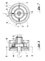
- a rotation angle sensor is shown in FIGS. 1 and 2.
- Both Hall IC elements 1, 2 are on a circuit board 14 from which a CAN bus or an analog signal is sent is led outside.
- the housing 10 is the printed circuit board 14 closed opposite with a lid 11.
- the wave 13 moves in a bearing bush 12 which is in the housing 10 is arranged.
- the ring magnet element 3 is divided into two.
- One half-circle segment has a north and encompassing outside inside a south polarity.
- the second ring magnetic element half has a north and outside around encompassing a south polarity. This creates a two-pole radial Ring magnet element that looks like a bar magnet behaves.
- the magnetic flux runs in the N and S designated areas radially. Only in the division area there are field irregularities.
- the Hall IC elements are conventional Hall measuring elements, each as an integrated circuit are realized.
- the two Hall IC elements 1, 2 are with connected to an evaluation unit 9 (see FIG. 3).
- the evaluation unit 9 consists of an arithmetic unit (CPU) 93, connected to a storage unit 94.
- CPU central processing unit
- On the input side are on the calculator 93, an analog-digital converter 91 and Analog-digital converter 92 arranged.
- the analog-to-digital converter 91 is with the Hall IC element 1 and the analog-to-digital converter 92 connected to Hall IC element 2.
- This configuration can be done either through a universal Microcomputer or by a user computer circuit (ASIC) can be realized.
- ASIC user computer circuit
- This magnetic flux is generated by each Hall IC element 1, 2 recorded as a Hall IC voltage curve UH1, UH2.
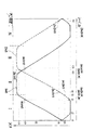
- the Hall IC voltage curve UH1, UH2 depending on Position angle ⁇ is shown in Fig. 4. Every course of tension has a sinusoidal configuration.
- the Hall IC voltage profile UH1 has I, which ranges from 0 ° to 90 °, a linear course on which there is a curved and flattened course in the second Quadrant II connects from 90 ° to 180 °.
- the next straight course lies in the third quadrant III from 180 ° to 270 °, in which the fourth quadrant IV is from 270 ° to 360 ° again a flattened, curved course follows.
- the Hall IC voltage profile UH2 is offset by 90 ° compared to the Hall IC voltage curve UH1, i.e. that its flattened curved part in the first quadrant, the first linear part in the second quadrant, in the third quadrant its curved and flattened part and its straight Part are then in the fourth quadrant.
- 4 makes the advantages of being 90 ° apart Hall IC elements 1, 2 particularly clearly, because in each Quadrants is a linear area that is accurate Measurement of the angular position from 0 ° to 360 ° enables.
- the program makes it clear that one of the Hall IC voltage waveforms UH1, UH2 on the one hand measurement curve and on the other decision curve is that when defining one of the Hall IC voltage waveforms UH1, UH2 as a measurement curve using the Decision curve is determined which of the determined To assign flux voltage measurements to a specific angle are.
- the assignment can be made in the storage unit 94 be made in tabular form.
- a forward voltage value UH1M1 measured by four volts. This measured value of 4 volts corresponds often the Hall IC voltage curve UH1, an angle of 72 ° or 189 °.
- the one Angle of 90 ° can be assigned.
- the evaluation unit 9 decides now that the Hall IC voltage curve UH2 the decision curve and the Hall IC voltage curve UH1 die Measurement curve is. It is stored in the program that at a Position angle ⁇ H2M1 at 72 ° the actual starting angle ⁇ 1 is and gives a corresponding output signal A1, A2 from.
- the Hall IC element 1 is a forward voltage value UH1M2 measured from 4.5 volts. This angle is 90 ° and assign 170 ° as ⁇ H1M2.
- the second Hall IC element 2 measures a forward voltage measurement UH2M2 of 1 volt, the both an angle of 99 ° and 351 ° can be assigned.
- the logic in the form of the evaluation unit 9 decides based on the program that the Hall IC voltage curve UH1 Decision curve and the Hall IC voltage curve UH2 Measurement curve is. It is stored in the program that with these Values of the forward voltage measurement UHM2 of 1 volt Position angle ⁇ H2M2 as the actual position angle ⁇ 2 is to be output.
- Deciding which curve to measure and which curve Decision curve and which measured value is output can be done in the form of a table which, as already mentioned, is stored in the storage unit.
- the computer compares the individual values and then leads under The program made the appropriate decisions by.
- FIG. 5 shows a torsion sensor. It consists of two rotation angle sensors arranged on a shaft 43, such as they have already been described.
- Each rotation angle sensor has a two-pole radial Ring magnet element 33, 53 on that of a stator element 34, 54 is connected to the shaft 43. Every ring magnet element 33, 53 rotates in a stator element 34, 54 that surrounded by a housing 40, 60 and with a cover 41, 61 is closed. In front of the cover is a printed circuit board 44 64 positioned.
- Air gaps 35, 36, 37, 38 and 55, 56, 57, 58 introduced, 6 and 7 show.
- a Hall IC element arranged so that this also at an angle ⁇ are offset from each other by 90 °.
- Each of the Hall IC elements 31, 32 and 51, 52 are each with a Evaluation unit (not shown) connected, the same constructed as the evaluation unit 9 already described is.
- a tongue 46 is of the shaft 43 cleaved.
- the ring magnetic receiving element is on the tongue 46 45 and on the rest of the shaft 43 the ring magnetic receiving element 65 arranged.
- the tongue 46 enables one finer and more precise measurement of the torsion of shaft 43.
- the shaft 43 is from a bearing bush 62 and the Tongue 46 surrounded by a bearing bush 42.
- each rotation angle sensor gives the rotation Shaft a position angle ⁇ when reaching a position as output signal A. If there is no torsion, these are both output signals the same.
- the shaft 43 rotates the tongue 46, the twist is different Represents output signals whose difference is a measure of is the torsion or the torsion angle.
- the advantage of the described torsion sensor is that that the torsion of the shaft and at the same time its position can be determined. This allows Storage of the values, conclusions on material stress determine at very specific angular positions. Becomes the torsion sensor is installed on a shaft 13 due to the redundant arrangement of two rotation angle sensors Measurement certainty and accuracy increased. If one of the falls Rotation angle sensors, the second still takes over Function of measuring the position of the rotating shaft. To the others can the output voltages of both rotation angle sensors to be used for mutual function monitoring to guarantee. Such monitoring is can always be used advantageously if the costs for a special monitoring unit in relation to costs of a rotation angle sensor manufactured in large quantities are high.
Landscapes
- Physics & Mathematics (AREA)
- General Physics & Mathematics (AREA)
- Transmission And Conversion Of Sensor Element Output (AREA)
Description
- einen von jedem Hall-IC-Element gemessenen Hall-IC-Spannungsverlauf aufnimmt,
- jeden aufgenommenen Fluß-Spannungsmeßwert einem Stellungswinkel zuordnet, und
- aus den den Fluß-Spannungsmeßwerten zugeordneten Stellungswinkeln den tatsächlichen Stellungswinkel rechnet und als Ausgangssignal ausgibt.
- daß auf wenigstens einer Welle ein erstes und ein zweites zweipolig-radiales Ringmagnetelement angeordnet ist,
- daß jedes Ringmagnetelement von einem Statorelement umgeben ist, in dem um einen gleichen Winkel versetzt jeweils wenigstens drei Luftspalte eingebracht sind, und
- daß in jeweils zwei nebeneinanderliegenden Luftspalten jedes Statorelementes jeweils ein Hall-IC-Element angeordnet ist.
- Fig. 1:
- einen Drehwinkelsensor in einem schematisch dargestellten Längsschnitt;
- Fig. 2
- einen Schnitt durch einen Drehwinkelsensor gemäß Fig. 1 entlang der Linie II - II;
- Fig. 3
- eine Auswerteeinheit für einen Drehwinkelsensor gemäß den Fig. 1 und 2;
- Fig. 4
- einen Hall-IC-Spannungsverlauf der beiden Hall-IC's in Abhängigkeit vom Stellungswinkel eines mit einer Welle verbundenen Ringmagnetelements eines Drehwinkelsensors gemäß Fig. 1 und 2;
- Fig. 5
- einen Torsionssensor, aufgebaut aus zwei auf einer Welle angeordneten Drehwinkelsensoren gemäß den Fig. 1 bis 4;
- Fig. 6
- einen Schnitt durch den ersten Winkelsensor eines Torsionssensors gemäß Fig. 5 entlang der Linie VI - VI;
- Fig. 7
- einen Schnitt durch den zweiten Winkelsensor eines Torsionssensors gemäß Fig. 5 entlang der Linie VII - VII und
- Fig. 8
- einen vergrößerten Ausschnitt der Welle, auf dem der Torsionssensor gemäß den Fig. 5 bis 7 angeordnet ist.
- ein Ringmagnetelement 3 auf, das von einem Ringmagnetaufnahmeelement 15 gehalten ist, das mit einer Welle 13 verbunden ist, und
- ein Statorelement 4, in das jeweils um einen Winkel ϕ von 90° ein Luftspalt 5, ein Luftspalt 6, ein Luftspalt 7 und ein Luftspalt 8 eingebracht sind, sowie
- ein Gehäuse 10, das das Ringmagnetelement 3 umgibt.
- 1, 2
- Hall-IC-Element
- 3
- Ringmagnetelement
- 4
- Statorelement
- 5, 6, 7, 8
- Luftspalt
- 9
- Auswerteeinheit
- 10
- Gehäuse
- 11
- Deckel
- 12
- Lagerbuchse
- 13
- Welle
- 14
- Leiterplatte
- 15
- Ringmagnetaufnahmeelement
- 31, 32, 51, 52
- Hall-IC-Element
- 33, 53
- Ringmagnetelement
- 34, 54
- Statorelement
- 35, 36, 37, 38 55, 56, 57, 58
- Luftspalt
- 40, 60
- Gehäuse
- 41, 61
- Deckel
- 42, 62
- Lagerbuchse
- 43
- Welle
- 44, 64
- Leiterplatte
- 45, 65
- Ringmagnetaufnahmeelement
- 46
- Zunge
- 91, 92
- Analog-Digital-Wandler
- 93 94
- Speichereinheit
- 95
- Digital-Analog-Wandler
- 96
- CAN-BUS-Interface
- α
- Stellungswinkel
- αH1M1, αH1M2, αH2M1, αH2M2
- Stellungswinkel
- U
- Spannung
- UH1, UH2
- Hall-IC-Spannungsverlauf
- UH1M1, UH1M2, UH2M1, UH2M2
- Fluß-Spannungsmeßwert
- I, II, III, IV
- Quadrant
- A1
- digitales Ausgangssignal
- A2
- analoges Ausgangssignal
Claims (7)
- Vorrichtung zur Ermittlung der Position rotierender Wellen mitgekennzeichnet durch eine Auswerteeinheit (9), die mit den beiden in dem Statorelement (4) angeordneten Hall-IC-Elementen (1, 2) verbunden ist, diewenigstens einem zweipolig-radialen Ringmagnetelement (3) das mit der Welle (13) verbunden ist, undwenigstens einem Statorelement (4) aus einem magnetisch leitenden Material,in dem das Ringmagnetelement (3) angeordnet ist undin dem um einen gleichen Winkel (ϕ) versetzt wenigstens drei Luftspalte (5, 6, 7, 8) eingebracht sind,wobei in zwei nebeneinanderliegenden Luftspalten (5, 6,7, 8) jeweils ein Hall-IC-Element (1, 2) angeordnet ist, das bei einer Drehung des Ringmagnetelements relativ zum Statorelement Fluß-Spannungsmeßwerte (UH1M1, UH2M1; UH1M2, UH2M2) abgibt,einen von jedem Hall-IC-Element (1, 2) gemessenen Hall-IC-Spannungsverlauf (UH1, UH2) aufnimmt,jeden aufgenommenen Fluß-Spannungsmeßwert (UH1M1,UH2M1; UH1M2, UH2M2) einem Stellungswinkel (αH1M1, αH2M1; αH1M2, αH2M2) auf den Hall-IC-Spannungsverläufen (UH1, UH2) zuordnet, undaus den den Fluß-Spannungsmeßwerten (UH1M1, UH2M1; UH1M2, UH2M2) zugeordneten Stellungswinkeln (αH1M1, αH2M1; αH1M2, αH2M2) den tatsächlichen Stellungswinkel (α1; α2) rechnet und als Ausgangssignal (A1, A2)
- Vorrichtung nach Anspruch 1, dadurch gekennzeichnet,daß auf wenigstens einer Welle (43) ein erstes und ein zweites zweipolig-radiales Ringmagnetelement (33, 53) angeordnet ist,daß jedes Ringmagnetelement (33, 53) von einem Statorelement (34, 54) umgeben ist, in dem um einen gleichen Winkel (ϕ) versetzt jeweils wenigstens drei Luftspalte (35, 36, 37, 38, 55, 56, 57, 58) eingebracht sind, unddaß in jeweils zwei nebeneinanderliegenden Luftspalten (35, 36, 37, 38, 55, 56, 57, 58) jedes Statorelementes (34, 54) jeweils ein Hall-IC-Element (31, 32, 51, 52) angeordnet ist.
- Vorrichtung nach Anspruch 2, daß von der Welle (43) eine axial verlaufende Zunge (46) abgespalten und einendes gehalten ist oder daß die Welle aus zwei miteinander verbundenen Teilwellen besteht.
- Vorrichtung nach Anspruch 1 oder 2 oder 3, dadurch gekennzeichnet, daß die Auswerteeinheit (9) als Mikrorechner oder Anwender-Rechner-Schaltkreis (ASIC) ausgebildet ist und wenigstens aufweistein Rechenwerk (CPU) (93),das mit einer Speichereinheit (94) verbunden ist,an das eingangsseitig parallel zueinanderliegend ein erster und ein zweiter Analog-Digital-Wandler (91, 92), die jeweils mit einem der Hall-IC-Elemente (1, 2) verbunden sind, undan dem ausgangsseitig ein digitales oder analoges Ausgangssignal (A1, A2) ansteht.
- Vorrichtung nach einem der Ansprüche 1 bis 4, dadurch gekennzeichnet, daß in jedem der Statorelemente (4) vier, in einem Winkel ϕ = 90° beabstandet zueinander angeordnete Luftspalte (5, 6, 7, 8) eingebracht sind.
- Vorrichtung nach einem der Ansprüche 1 bis 5, daß jedes Ringmagnetelement (3) von einem Ringmagnetaufnahmeelement (15) gehalten, das mit der Welle (13) verbunden ist.
- Vorrichtung nach einem der Ansprüche 1 bis 6, dadurch gekennzeichnet, daß ein Statorelement (4) in wenigstens einem Gehäuse (10) angeordnet ist.
Applications Claiming Priority (3)
| Application Number | Priority Date | Filing Date | Title |
|---|---|---|---|
| DE19716985A DE19716985A1 (de) | 1997-04-23 | 1997-04-23 | Vorrichtung zur Ermittlung der Position und/oder Torsion rotierender Wellen |
| DE19716985 | 1997-04-23 | ||
| PCT/EP1998/002397 WO1998048244A1 (de) | 1997-04-23 | 1998-04-23 | Vorrichtung zur ermittlung der position und/oder torsion rotierender wellen |
Publications (2)
| Publication Number | Publication Date |
|---|---|
| EP0914590A1 EP0914590A1 (de) | 1999-05-12 |
| EP0914590B1 true EP0914590B1 (de) | 2003-10-22 |
Family
ID=7827394
Family Applications (1)
| Application Number | Title | Priority Date | Filing Date |
|---|---|---|---|
| EP98924180A Expired - Lifetime EP0914590B1 (de) | 1997-04-23 | 1998-04-23 | Vorrichtung zur ermittlung der position rotierender wellen |
Country Status (4)
| Country | Link |
|---|---|
| US (1) | US6201389B1 (de) |
| EP (1) | EP0914590B1 (de) |
| DE (2) | DE19716985A1 (de) |
| WO (1) | WO1998048244A1 (de) |
Cited By (1)
| Publication number | Priority date | Publication date | Assignee | Title |
|---|---|---|---|---|
| EP1752361A1 (de) | 2005-08-11 | 2007-02-14 | ZF Lenksysteme GmbH | Vorrichtung zur Ermittlung der Position und eines Drehmoments einer Welle |
Families Citing this family (69)
| Publication number | Priority date | Publication date | Assignee | Title |
|---|---|---|---|---|
| DE10315448A1 (de) | 2003-04-04 | 2004-10-28 | Ab Elektronik Gmbh | Elektronisches Gassystem für Motorräder |
| FR2786266B1 (fr) * | 1998-11-20 | 2001-01-19 | Moving Magnet Tech | Capteur de position a sonde de hall |
| US6326780B1 (en) | 1998-12-01 | 2001-12-04 | Visteon Global Technologies, Inc. | Magnetic field concentrator array for rotary position sensors |
| GB2379025A (en) * | 1998-12-01 | 2003-02-26 | Ford Motor Co | Rotary position sensor |
| DE19903653C2 (de) * | 1999-01-29 | 2002-07-18 | A B Elektronik Gmbh | Gurtstraffer |
| US20020124663A1 (en) * | 1999-04-07 | 2002-09-12 | Yoshitomo Tokumoto | Rotational angle detecting device, torque detecting device and steering apparatus |
| DE10023695B4 (de) * | 1999-05-17 | 2004-06-09 | Ab Elektronik Gmbh | Verstellvorrichtung |
| GB2352522B (en) * | 1999-05-28 | 2003-08-06 | Caithness Dev Ltd | A sensor |
| JP4378814B2 (ja) * | 1999-07-16 | 2009-12-09 | 株式会社日本自動車部品総合研究所 | 回転角検出装置 |
| JP2001115737A (ja) * | 1999-10-18 | 2001-04-24 | Koito Mfg Co Ltd | パワーウインドの安全装置 |
| US6577119B1 (en) | 1999-12-01 | 2003-06-10 | Sena Yaddehige | Pedal position sensor with magnet movable relative to a magnetic field sensor located in a stator channel |
| JP2002022406A (ja) * | 2000-07-11 | 2002-01-23 | Yazaki Corp | 回転角センサ |
| US6518750B1 (en) * | 2000-08-10 | 2003-02-11 | Delphi Technologies, Inc. | Angular position sensor including rotor with spaced bar magnets |
| US6566860B1 (en) * | 2000-09-14 | 2003-05-20 | Delphi Technologies, Inc. | Method for temperature compensation for the output of an angular position sensor |
| AT4639U1 (de) * | 2000-10-23 | 2001-09-25 | Austria Mikrosysteme Int | Winkelmesseinrichtung |
| US7208939B2 (en) * | 2001-02-28 | 2007-04-24 | Bvr Technologies Co. | Methods and apparatus for sensing angular position and speed of a rotatable shaft utilizing linearized annular magnet and commutated ratiometric hall sensors |
| DE10132215A1 (de) * | 2001-07-03 | 2003-01-23 | Philips Corp Intellectual Pty | Anordnung zum Messen der Winkelposition eines Objektes |
| ITTO20010730A1 (it) * | 2001-07-24 | 2003-01-24 | Campagnolo Srl | Trasduttore di grandezze angolari. |
| DE10141372A1 (de) * | 2001-08-23 | 2003-03-13 | Philips Corp Intellectual Pty | Magnetoresistiver Winkelsensor |
| DE10159437B4 (de) * | 2001-12-04 | 2005-06-30 | Ab Elektronik Gmbh | Drehwinkelsensor |
| JP2003240652A (ja) * | 2002-02-15 | 2003-08-27 | Denso Corp | 出力補正回路内蔵型半導体センサ及びトーションバー式トルクセンサ |
| EP1504238A1 (de) * | 2002-05-10 | 2005-02-09 | Padraig Keane | Winkelsensor |
| WO2003098147A1 (en) * | 2002-05-15 | 2003-11-27 | American Electronic Components, Inc. | Through the hole rotary position sensor |
| DE10222634B4 (de) * | 2002-05-17 | 2009-04-02 | Ab Elektronik Gmbh | Verfahren zur Überwachung von Versorgungsspannungen bei Drehwinkelsensoren mit Hall-Elementen |
| DE10222468A1 (de) * | 2002-05-22 | 2003-12-11 | A B Elektronik Gmbh | Vorrichtung zur Erzeugung von Ausgangsspannungen |
| DE10222467A1 (de) * | 2002-05-22 | 2003-12-11 | A B Elektronik Gmbh | GMR-Drehwinkelsensor |
| US6927566B2 (en) | 2002-05-22 | 2005-08-09 | Ab Eletronik Gmbh | Device for generating output voltages |
| DE10226062A1 (de) | 2002-06-12 | 2004-01-08 | Ab Elektronik Gmbh | Weitwinkel-Drehwinkelsensor |
| DE10241214B4 (de) * | 2002-09-06 | 2011-01-27 | Automotive Lighting Reutlingen Gmbh | Scheinwerferanordnung für Kraftfahrzeuge |
| DE10245926B4 (de) | 2002-10-02 | 2005-04-07 | Ab Elektronik Gmbh | Bodenpedal mit Drehwinkelsensor |
| DE10254552A1 (de) * | 2002-11-21 | 2004-06-03 | Siemens Ag | Winkelpositionsgeber |
| JP4118755B2 (ja) | 2003-01-14 | 2008-07-16 | 株式会社日本自動車部品総合研究所 | 回転角センサ及びこの回転角センサを具備した回転角検出装置 |
| FR2855591A1 (fr) * | 2003-05-27 | 2004-12-03 | Valeo Vision | Dispositif projecteur muni d'un systeme de determination de position ou de variation de position |
| US20040257071A1 (en) * | 2003-06-20 | 2004-12-23 | Jack Chen | Angular position sensor |
| US6873151B2 (en) * | 2003-07-08 | 2005-03-29 | Delphi Technologies, Inc. | Sensor assembly for sensing angular position |
| JP4233958B2 (ja) * | 2003-08-29 | 2009-03-04 | 株式会社日本自動車部品総合研究所 | 回転角検出装置 |
| JP4786138B2 (ja) * | 2003-09-26 | 2011-10-05 | ハイデルベルガー ドルツクマシーネン アクチエンゲゼルシヤフト | 被印刷体枚葉紙を処理する機械 |
| US7023201B2 (en) * | 2003-12-15 | 2006-04-04 | Texas Instruments Incorporated | Magnetic position sensor apparatus and method |
| US6940275B2 (en) * | 2003-12-15 | 2005-09-06 | Texas Instruments Incorporated | Magnetic position sensor apparatus and method |
| EP1706716B1 (de) * | 2004-01-20 | 2011-09-14 | Valeo Schalter und Sensoren GmbH | Vorrichtung zum bestimmen eines lenkwinkels und eines an einer lenkwelle ausgeübten drehmoments |
| JP4518818B2 (ja) * | 2004-03-17 | 2010-08-04 | 三菱電機株式会社 | トルクセンサ |
| US8212551B2 (en) * | 2004-08-03 | 2012-07-03 | Ntn Corporation | Bearing with absolute angle sensor |
| JP4039436B2 (ja) * | 2004-08-06 | 2008-01-30 | 株式会社デンソー | 回転角検出装置 |
| DE102004056049A1 (de) | 2004-11-19 | 2006-06-01 | Ab Elektronik Gmbh | Sensor und Verfahren zur Herstellung eines Sensors |
| JP4354397B2 (ja) * | 2004-12-27 | 2009-10-28 | 富士通株式会社 | 磁気力顕微鏡用の磁界発生装置 |
| US7375509B2 (en) * | 2005-03-02 | 2008-05-20 | Stoneridge Control Devices, Inc. | System and method for position sensing using inflection point position sensing of a sensor output |
| GB2426591B (en) * | 2005-05-27 | 2009-12-30 | Tt Electronics Technology Ltd | Sensing apparatus and method |
| EP1907798B1 (de) * | 2005-07-26 | 2009-12-02 | ebm-papst St. Georgen GmbH & Co. KG | Elektromotor mit einem absolutwert-drehwinkelsensor, und verfahren zur erzeugung eines drehwinkel-absolutwerts |
| US7999537B2 (en) | 2006-01-12 | 2011-08-16 | Timken Us Corporation | Magnetic sensor with high and low resolution tracks |
| DE102006007668A1 (de) * | 2006-02-18 | 2007-08-23 | Schaeffler Kg | Messeinrichtung zur Bestimmung eines Drehwinkels |
| KR100800126B1 (ko) * | 2006-08-17 | 2008-01-31 | 에스엘 주식회사 | 전자식 변속 레버 |
| DE102007024249A1 (de) * | 2007-05-18 | 2008-12-11 | CoActive Technologies, Inc., Greenwich | Vorrichtung zum Erfassen eines Stellwinkels eines um eine Achse drehbaren Elementes |
| DE102009021081B4 (de) * | 2008-07-18 | 2017-07-06 | Asm Automation Sensorik Messtechnik Gmbh | Magnetischer Winkelsensor |
| WO2010035418A1 (ja) * | 2008-09-26 | 2010-04-01 | アサヒビール株式会社 | 落体式粘度計用の落体速度測定センサ、及び、落下速度測定方法 |
| US20100176803A1 (en) * | 2009-01-12 | 2010-07-15 | Infineon Technologies Ag | Angle sensor with flux guides, rotatable magnet and magnetic sensor |
| CN101876125B (zh) * | 2009-04-30 | 2014-06-18 | 浙江中科德润科技有限公司 | 电动缝纫机 |
| CN101875369B (zh) * | 2009-04-30 | 2013-06-12 | 浙江中科德润科技有限公司 | 伺服助力转向系统及其控制方法 |
| CN101877521B (zh) * | 2009-04-30 | 2013-01-02 | 浙江中科德润科技有限公司 | 多节伺服潜油电机 |
| CN101877267B (zh) * | 2009-04-30 | 2013-01-02 | 浙江中科德润科技有限公司 | 一种导磁环 |
| CN101886932B (zh) * | 2009-04-30 | 2013-02-06 | 浙江中科德润科技有限公司 | 位置检测装置及其信号处理装置与方法 |
| CN101876558B (zh) * | 2009-04-30 | 2013-03-06 | 浙江中科德润科技有限公司 | 位置检测装置及其信号处理装置和方法 |
| CN101875199B (zh) * | 2009-04-30 | 2013-03-06 | 浙江中科德润科技有限公司 | 减速装置及其控制方法 |
| KR101197417B1 (ko) | 2010-09-06 | 2012-11-05 | 주식회사 동희산업 | 스톱램프스위치 기능을 구비한 브레이크페달의 변위감지센서 |
| CN104729933B (zh) * | 2015-03-17 | 2017-10-20 | 中国科学院力学研究所 | 一种高分辨率电磁式微尺度扭转试验机及其试验方法 |
| KR101774666B1 (ko) * | 2015-12-03 | 2017-09-04 | 현대자동차주식회사 | 세이프티 파워 윈도우 시스템 및 그 동작 방법 |
| US20170191561A1 (en) * | 2016-01-04 | 2017-07-06 | Dura Operating, Llc | Shift detection system |
| SE541620C2 (en) * | 2017-07-03 | 2019-11-12 | Allied Motion Stockholm Ab | Steering wheel sensor unit comprising a ring magnet |
| US11675027B2 (en) * | 2019-12-27 | 2023-06-13 | Woodward, Inc. | Multi-channel magnetic sensor device |
| CN115265413A (zh) * | 2022-09-01 | 2022-11-01 | 北京航空航天大学 | 一种用于微小推力测量和卫星姿轨控仿真的角位移测量方法 |
Family Cites Families (12)
| Publication number | Priority date | Publication date | Assignee | Title |
|---|---|---|---|---|
| US3194990A (en) * | 1965-07-13 | Hall plate solid state resolver | ||
| US3152261A (en) * | 1961-04-12 | 1964-10-06 | United Aircraft Corp | Variable reluctance hall effect resolver |
| US4663601A (en) * | 1984-11-21 | 1987-05-05 | Xomox Corporation | Magnetic switch housing assembly |
| JPS6457136A (en) * | 1987-05-12 | 1989-03-03 | Nippon Denso Co | Torque detecting apparatus |
| EP0368687A3 (de) * | 1988-09-13 | 1991-09-25 | Consulab Inc. | Positionsmesseinrichtung |
| US4984474A (en) * | 1988-09-30 | 1991-01-15 | Copal Company Limited | Torque sensor |
| FR2660028B1 (fr) * | 1990-03-20 | 1994-12-09 | Roulements Soc Nouvelle | Roulement a capteur de position angulaire. |
| FR2670286B1 (fr) * | 1990-12-05 | 1993-03-26 | Moving Magnet Tech | Capteur magnetique de position et de vitesse a sonde de hall. |
| DE4141000B4 (de) * | 1990-12-13 | 2010-11-25 | Papst Licensing Gmbh & Co. Kg | Anordnungen und Verfahren zur Messung von Drehwinkeln |
| DE4231646A1 (de) * | 1992-02-11 | 1993-08-12 | A B Elektronik Gmbh | Messanordnung zur bestimmung der torsion und eines anliegenden torsionsmomentes |
| DE29520111U1 (de) * | 1995-09-29 | 1997-02-06 | Bosch Gmbh Robert | Meßvorrichtung zur berührungslosen Erfassung einer Relativbewegung |
| DE19630764A1 (de) * | 1995-09-29 | 1997-04-03 | Bosch Gmbh Robert | Meßvorrichtung zur berührungslosen Erfassung einer Relativbewegung |
-
1997
- 1997-04-23 DE DE19716985A patent/DE19716985A1/de not_active Withdrawn
-
1998
- 1998-04-23 EP EP98924180A patent/EP0914590B1/de not_active Expired - Lifetime
- 1998-04-23 WO PCT/EP1998/002397 patent/WO1998048244A1/de not_active Ceased
- 1998-04-23 US US09/202,907 patent/US6201389B1/en not_active Expired - Fee Related
- 1998-04-23 DE DE59809961T patent/DE59809961D1/de not_active Expired - Fee Related
Cited By (1)
| Publication number | Priority date | Publication date | Assignee | Title |
|---|---|---|---|---|
| EP1752361A1 (de) | 2005-08-11 | 2007-02-14 | ZF Lenksysteme GmbH | Vorrichtung zur Ermittlung der Position und eines Drehmoments einer Welle |
Also Published As
| Publication number | Publication date |
|---|---|
| DE59809961D1 (de) | 2003-11-27 |
| US6201389B1 (en) | 2001-03-13 |
| WO1998048244A1 (de) | 1998-10-29 |
| EP0914590A1 (de) | 1999-05-12 |
| DE19716985A1 (de) | 1998-10-29 |
Similar Documents
| Publication | Publication Date | Title |
|---|---|---|
| EP0914590B1 (de) | Vorrichtung zur ermittlung der position rotierender wellen | |
| DE19818799C2 (de) | Verfahren und Vorrichtung zum Messen von Winkeln | |
| DE102009044542B3 (de) | Wälzlager mit einer Sensoreinheit | |
| DE69525819T2 (de) | Kapazitives Verschiebungsmessgerät | |
| DE69103665T2 (de) | Drehmomentmessvorrichtung an einer Welle. | |
| DE102008059775A1 (de) | Absolut messende Lenkwinkelsensoranordnung | |
| CH652496A5 (en) | Integrated position sensor at an actuator cylinder | |
| DE202007014319U1 (de) | Magnetfeldempfindlicher Sensor | |
| DE4440214A1 (de) | Drehgeber mit Hallsensoren | |
| DE102019127297A1 (de) | Sensorvorrichtung zur Erfassung der Drehwinkelstellung einer drehbeweglichen Welle sowie Lenkungsanordnung eines Fahrzeugs | |
| EP1324050A2 (de) | Anordnung zum Detektieren der Bewegung eines Encoders | |
| DE10052148B4 (de) | Vermessungsinstrument mit einem magnetischen Inkremental-Drehcodierer | |
| DE202005011361U1 (de) | Magnetfeldempfindlicher Sensor | |
| DE102013207621B4 (de) | Winkelmessung, insbesondere berührungslos, mit Einzelsensoren | |
| DE19800774B4 (de) | Verfahren und magnetische Maßverkörperung zur Generierung eines Referenzsignals sowie Herstellungsverfahren für eine solche magnetische Maßverkörperung | |
| DE102010029640B4 (de) | Drehgeberzahnvorrichtung | |
| EP2343506A2 (de) | Längenmessvorrichtung | |
| DE102004001570A1 (de) | Magnetische Messvorrichtung | |
| EP0566923B1 (de) | Vorrichtung zum berührungslosen Messen der axialen Lage eines rotierenden Körpers | |
| DE9305385U1 (de) | Anordnung zur berührungsfreien Erfassung der Drehzahl oder Position eines drehbaren Geberteils | |
| WO1989011079A1 (en) | Position-coded goniometer | |
| DE19632656A1 (de) | Verfahren und Vorrichtung zum berührungslosen Erfassen der Lage oder der Drehstellung eines Gegenstandes | |
| DE102005055905B4 (de) | Längenmessanordnung mit einem magnetischen Maßstab mit gegenläufiger Magnetisierung | |
| DE102021106095B4 (de) | Vorrichtung zur Bestimmung der Winkelposition eines Drehelementes | |
| EP0247567B1 (de) | Absolute Winkelmessvorrichtung |
Legal Events
| Date | Code | Title | Description |
|---|---|---|---|
| PUAI | Public reference made under article 153(3) epc to a published international application that has entered the european phase |
Free format text: ORIGINAL CODE: 0009012 |
|
| 17P | Request for examination filed |
Effective date: 19990118 |
|
| AK | Designated contracting states |
Kind code of ref document: A1 Designated state(s): DE FR GB IT |
|
| 17Q | First examination report despatched |
Effective date: 20020913 |
|
| GRAH | Despatch of communication of intention to grant a patent |
Free format text: ORIGINAL CODE: EPIDOS IGRA |
|
| RTI1 | Title (correction) |
Free format text: DEVICE FOR DETERMINING THE POSITION OF ROTATING SHAFTS |
|
| GRAS | Grant fee paid |
Free format text: ORIGINAL CODE: EPIDOSNIGR3 |
|
| GRAA | (expected) grant |
Free format text: ORIGINAL CODE: 0009210 |
|
| AK | Designated contracting states |
Kind code of ref document: B1 Designated state(s): DE FR GB IT |
|
| REG | Reference to a national code |
Ref country code: GB Ref legal event code: FG4D Free format text: NOT ENGLISH |
|
| GBT | Gb: translation of ep patent filed (gb section 77(6)(a)/1977) |
Effective date: 20031022 |
|
| REF | Corresponds to: |
Ref document number: 59809961 Country of ref document: DE Date of ref document: 20031127 Kind code of ref document: P |
|
| ET | Fr: translation filed | ||
| PLBE | No opposition filed within time limit |
Free format text: ORIGINAL CODE: 0009261 |
|
| STAA | Information on the status of an ep patent application or granted ep patent |
Free format text: STATUS: NO OPPOSITION FILED WITHIN TIME LIMIT |
|
| 26N | No opposition filed |
Effective date: 20040723 |
|
| PGFP | Annual fee paid to national office [announced via postgrant information from national office to epo] |
Ref country code: DE Payment date: 20050404 Year of fee payment: 8 |
|
| PGFP | Annual fee paid to national office [announced via postgrant information from national office to epo] |
Ref country code: GB Payment date: 20050411 Year of fee payment: 8 |
|
| PGFP | Annual fee paid to national office [announced via postgrant information from national office to epo] |
Ref country code: FR Payment date: 20050425 Year of fee payment: 8 |
|
| PG25 | Lapsed in a contracting state [announced via postgrant information from national office to epo] |
Ref country code: GB Free format text: LAPSE BECAUSE OF NON-PAYMENT OF DUE FEES Effective date: 20060423 |
|
| PGFP | Annual fee paid to national office [announced via postgrant information from national office to epo] |
Ref country code: IT Payment date: 20060430 Year of fee payment: 9 |
|
| PG25 | Lapsed in a contracting state [announced via postgrant information from national office to epo] |
Ref country code: DE Free format text: LAPSE BECAUSE OF NON-PAYMENT OF DUE FEES Effective date: 20061101 |
|
| GBPC | Gb: european patent ceased through non-payment of renewal fee |
Effective date: 20060423 |
|
| REG | Reference to a national code |
Ref country code: FR Ref legal event code: ST Effective date: 20061230 |
|
| PG25 | Lapsed in a contracting state [announced via postgrant information from national office to epo] |
Ref country code: FR Free format text: LAPSE BECAUSE OF NON-PAYMENT OF DUE FEES Effective date: 20060502 |
|
| PG25 | Lapsed in a contracting state [announced via postgrant information from national office to epo] |
Ref country code: IT Free format text: LAPSE BECAUSE OF NON-PAYMENT OF DUE FEES Effective date: 20070423 |