EP0909727B1 - Traggestell für Förderer, insbesondere für Rollenbahnen - Google Patents
Traggestell für Förderer, insbesondere für Rollenbahnen Download PDFInfo
- Publication number
- EP0909727B1 EP0909727B1 EP98250321A EP98250321A EP0909727B1 EP 0909727 B1 EP0909727 B1 EP 0909727B1 EP 98250321 A EP98250321 A EP 98250321A EP 98250321 A EP98250321 A EP 98250321A EP 0909727 B1 EP0909727 B1 EP 0909727B1
- Authority
- EP
- European Patent Office
- Prior art keywords
- profile
- elements
- screw
- supporting framework
- framework according
- Prior art date
- Legal status (The legal status is an assumption and is not a legal conclusion. Google has not performed a legal analysis and makes no representation as to the accuracy of the status listed.)
- Expired - Lifetime
Links
- 230000000295 complement effect Effects 0.000 claims description 3
- 210000003746 feather Anatomy 0.000 claims description 2
- 230000000717 retained effect Effects 0.000 claims 1
- 230000005484 gravity Effects 0.000 abstract 1
- 238000003780 insertion Methods 0.000 description 3
- 230000037431 insertion Effects 0.000 description 3
- 230000015572 biosynthetic process Effects 0.000 description 2
- 230000005540 biological transmission Effects 0.000 description 1
- 238000005266 casting Methods 0.000 description 1
- 238000010276 construction Methods 0.000 description 1
- 230000001419 dependent effect Effects 0.000 description 1
- 238000005553 drilling Methods 0.000 description 1
- 238000007373 indentation Methods 0.000 description 1
- 238000009434 installation Methods 0.000 description 1
- 238000004519 manufacturing process Methods 0.000 description 1
- 239000000725 suspension Substances 0.000 description 1
Images
Classifications
-
- B—PERFORMING OPERATIONS; TRANSPORTING
- B65—CONVEYING; PACKING; STORING; HANDLING THIN OR FILAMENTARY MATERIAL
- B65G—TRANSPORT OR STORAGE DEVICES, e.g. CONVEYORS FOR LOADING OR TIPPING, SHOP CONVEYOR SYSTEMS OR PNEUMATIC TUBE CONVEYORS
- B65G21/00—Supporting or protective framework or housings for endless load-carriers or traction elements of belt or chain conveyors
- B65G21/02—Supporting or protective framework or housings for endless load-carriers or traction elements of belt or chain conveyors consisting essentially of struts, ties, or like structural elements
Definitions
- the invention relates to a support frame for conveyors, in particular for roller conveyors according to the preamble of claim 1.
- a support frame is already known from European patent application EP 0 623 530 A1 known for the suspension of a overhead conveyor, which essentially consists of extruded profile elements that are connected to the Support frame can be screwed together.
- the rectangular in cross section For this purpose, profile elements point on all longitudinal sides and in their longitudinal direction running T-shaped grooves on, in the hammer head-shaped terminal blocks in the form of Screw nuts can be inserted from above through the opening in the groove. After this The clamp stones are inserted within the groove by almost 90 ° in front of them Fastening twisted so that the clamp on the inside of the Can undercut the groove. About that of the clamp screw picked up and protruding from the groove is thus a Connection element at any point along the profile element screwed.
- each connecting element has a bore through which the screw of the clamping block is passed.
- the at least two holes on the connecting element can Profile elements at the desired angles to each other, one above the other and to Extension screwed together one behind the other.
- Alignments and positions of the profile elements can be determined in advance, so that the installation is made considerably easier. Also through the continuous T-slot and the different design of the connecting elements is a big one A variety of mounting positions achieved.
- Support frames designed in this way have the disadvantage that the profile elements only are connected to each other via clamping forces and thus with regard to their resilience are limited. When overloaded, the clamps tend to slip in the T-shaped Groove.
- the design of the connecting elements in the manner of a pipe clamp with two Clamping areas can, however, prove to be disadvantageous because of the Screw connection pressed both clamping areas onto the tube profiles at the same time become.
- the clamping forces are directly dependent on the Manufacturing tolerances of the connecting element and the tube profiles, so that For example, the clamping force on the first tubular profile element is reduced when the second tubular profile has a larger diameter than intended. A Even clamping of the two profile tubes is therefore difficult to achieve.
- these connecting elements are also suitable, since they have a frictional connection work only for limited loads.
- the present invention has for its object a further support frame for To create conveyors, especially for roller conveyors, that are easy to assemble and is inexpensive and has secure connecting elements.
- the support frame is formed by the formation of the support frame from profile elements Wells and connecting elements that can be inserted into the wells complementary to the recesses formed shoulder bodies, the inserted connecting elements via a screw on the profile element be kept, a structurally simple support structure is created that is easy to install at the intended location. Furthermore, for one the required lengths of the profile elements in advance be cut so that only the individual profile elements for assembly the connecting elements must be screwed together.
- the connector form-fitting between the neck body and the recess in the profile element is formed, as a result of which the support frame in the assembled state high strength, especially stability. This also means that Loads safely transferred between the profile elements.
- constructively special Training has found a simple solution to create a positive connection of the wells proven as elongated through holes, in this Complementally designed neck body in the form of feather keys can be inserted.
- this connector offers good transmission properties for the Forces transverse to the direction of insertion.
- Securing the connection of the profile elements with the connecting body is made via a screw which is inserted in the Approach body arranged bore, which is aligned in the direction of insertion, is guided and is provided with a nut at the end facing away from the profile element.
- the screw head protrudes laterally over the attachment body out and is therefore based on the adjacent profile element.
- the profile elements in the form of U-profiles have proven to be preferred proven in the web of the depressions in the longitudinal direction of the profile elements are arranged one behind the other and at a distance from each other with the same distance. This results in a predetermined division, which is a sufficient number of Combination options of the connecting elements with the profile elements offers.
- the Connecting elements In order to be able to connect at least two profile elements to one another, the Connecting elements at least two spaced-apart shoulder bodies, connect to the level contact surfaces.
- the web of the U-shaped profile element supported and also by the screw held. So that a sufficient contact pressure through the screw connection is guaranteed - seen in the direction of insertion - the depth of the slot-shaped Through hole chosen slightly larger than the height of the neck body.
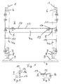
- FIG. 1 shows a view of a conveyor designed as a roller conveyor, which essentially consists of a roller conveyor unit indicated only by its longitudinal members 1 and a support frame 2.
- the longitudinal beam 1 and thus the conveyor is on the support frame 2 on a footprint 3, z. B. a hall floor. It is also fundamentally possible to use the support frame 2 for a hanging arrangement of the conveyor.
- the support frame 2 consists essentially of horizontally and vertically extending profile elements 4a and 4b, which are plugged together via connecting elements 5 to form an H-shaped frame seen in cross section and are then screwed together. Connection plates 6 are screwed to the upper ends of the vertically extending profile elements 4b, on the angled free ends of which the longitudinal members 1 are fastened.
- a connection element 7 is screwed, which has a vertically extending threaded bore 8, into which a support leg 9, which can thereby be adjusted in the vertical direction, is screwed.
- the connecting plates 6 and the connecting elements 7, the profile elements 4a and 4b have depressions 10 in the form of bores. These depressions 10 are arranged in the profile elements 4a and 4b, which are preferably designed as U-profiles, in their web 11. It can be seen from FIG. 1 and there in particular the horizontally extending profile element 4a that the depressions 10 are arranged next to one another with equal spacing and in the longitudinal direction of the profile element 4a one behind the other.
- depressions 10 are designed as elongated holes in order to positively accommodate complementary fitting bodies 12 which are arranged on the connecting elements 7 (see FIG. 2) and the connecting elements 5 (see FIG. 3). This ensures that the connecting elements 5 and the connecting elements 7 can be connected to the profile elements 4a, 4b in a rotationally secure manner.
- FIGS 2 and 3 which is a detailed view of the connecting element 7 and Connection element 5 show, it can be seen that the neck body 12 from a adjacent bearing surface 13 of the connecting element 5 or Connection element 7 protrudes and thus for the positive connection in the Wells 10 can be inserted.
- the side ones are in the inserted state Limits of the attachment body 12 in the form of the bearing surfaces 13 form-fitting the delimitation of the depressions 10 and the web 11 of the profile elements 4a, 4b abuts the bearing surfaces 13.
- the height of the neck body 12 that the height is chosen that this is slightly smaller than the wall thickness of the web 11 of the Profile elements 4a, 4b, so that on the side of the profile elements 4a, 4b supporting head of the screw 14, the support surfaces 13 sufficient to the Inside of the web 11 can be tightened.
- Connecting element 5 and the connecting element 7 are formed as a casting and thus the nut 15 is formed as part of a threaded bore.
- Figure 2 also shows that in addition to the positive connection part, the is formed by the neck body 12, the support surfaces 13 and the nut 15, a connection plate 17 is provided at right angles, in which the Threaded bore 8 for receiving the support foot 9 is arranged.
- connection plates 6 do not have the previously The described positive connection with the elongated depressions 10 are attached because in the present embodiment, these connection plates 6 for Alignment of the longitudinal beams 1 designed to be pivotable about a horizontal axis are and therefore a positive fit is not desirable here.
Landscapes
- Engineering & Computer Science (AREA)
- Mechanical Engineering (AREA)
- Rollers For Roller Conveyors For Transfer (AREA)
- Dental Preparations (AREA)
Description
- Figur 1
- eine Ansicht eines Traggestells für eine Rollenbahn,
- Figur 2
- eine Detailansicht eines Verbindungselementes des Traggestells gemäß Figur 1 und
- Figur 3
- eine Ansicht eines Anschlußelementes des Traggestells gemäß Figur 1.
Für die Verschraubung der Profilelemente 4a und 4b mit den Verbindungselementen 5, den Anschlußplatten 6 und den Anschlußelementen 7 weisen die Profilelemente 4a und 4b Vertiefungen 10 in Form von Bohrungen auf. Diese Vertiefungen 10 sind in dem vorzugsweise als U-Profile ausgebildeten Profilelementen 4a und 4b in deren Steg 11 angeordnet. Der Figur 1 und dort insbesondere dem horizontal verlaufenden Profilelement 4a ist zu entnehmen, daß die Vertiefungen 10 mit gleichen Abständen nebeneinander sowie in Längsrichtung des Profilelementes 4a hintereinander angeordnet sind. Diese Vertiefungen 10 sind als Langlöcher ausgebildet um komplementär paßfederförmig ausgebildete Ansatzkörper 12, die an den Anschlußelementen 7 (siehe Figur 2) und den Verbindungselementen 5 (siehe Figur 3) angeordnet sind, formschlüssig aufzunehmen. Hierdurch ist gewährleistet, daß die Verbindungselemente 5 und die Anschlußelemente 7 verdrehsicher mit den Profilelementen 4a,4b verbindbar sind.
- 1
- Längsträger
- 2
- Traggestell
- 3
- Aufstandsfläche
- 4a,b
- Profilelemente
- 5
- Verbindungselemente
- 6
- Anschlußplatte
- 7
- Anschlußelement
- 8
- Gewindebohrung
- 9
- Stützfuß
- 10
- Vertiefungen
- 11
- Steg
- 12
- Ansatzkörper
- 13
- Auflagefläche
- 14
- Schraube
- 15
- Mutter
- 16
- Bohrung
- 17
- Verbindungsplatte
Claims (7)
- Traggestell für Förderer, insbesondere für Rollenbahnen, bestehend aus für deren Verbindung untereinander an Verbindungselementen (5) anschraubbaren Profilelementen (4a,b), wobei die Verbindungselemente (5) erhobene Ansatzkörper (12) und die Profilelemente (4a,b) Vertiefungen (10) aufweisen, für die Verbindung eines Profilelementes (4a,b) mit einem Verbindungselement (5) der Ansatzkörper (12) des Verbindungselementes (5) in die hierzu komplementär ausgebildete Vertiefung (10) des Profilelementes (4a,b) formschlüssig einsteckbar ist und der Ansatzkörper (12) in der Vertiefung (10) über eine Verschraubung (Schraube 14, Mutter 15) haltbar ist,
dadurch gekennzeichnet, daß die Vertiefungen (10) als langlochförmige Durchgangsbohrungen ausgebildet sind und die Ansatzkörper (12) die Form einer Paßfeder aufweisen. - Traggestell nach Anspruch 1,
dadurch gekennzeichnet, daß je Verbindung zwischen einem Profilelement (4a,b) und einem Verbindungselement (5) ausschließlich ein in eine Vertiefung (10) einsteckbarer Ansatzkörper (12) vorgesehen ist. - Traggestell nach Anspruch 1 oder 2,
dadurch gekennzeichnet, daß in dem Ansatzkörper (12) eine Bohrung (16) zur Aufnahme einer Schraube (14) zur Verbindung des Profilelementes (4a,b) mit dem Verbindungselement (5) angeordnet ist. - Traggestell nach einem oder mehreren der Ansprüche 1 bis 3,
dadurch gekennzeichnet, daß die langlochförmigen Vertiefungen (10) mit ihrer Längserstreckung in Längsrichtung der Profilelemente (4a,b) ausgerichtet sind. - Traggestell nach einem oder mehreren der Ansprüche 1 bis 4,
dadurch gekennzeichnet, daß die Profilelemente (4a,b) als U-Profile ausgebildet sind, in dessen Steg (11) die Vertiefungen (10) in Längsrichtung der Profilelemente (4a,b) hintereinander sowie mit gleichen Abstand zueinander angeordnet sind. - Traggestell nach einem oder mehreren der Ansprüche 1 bis 4,
dadurch gekennzeichnet, daß die Verbindungselemente (5) mindestens zwei voneinander beabstandete Ansatzkörper (12) aufweisen, an die eine ebene Auflagefläche (13) für die Profilelemente (4a,b) angrenzt. - Traggestell nach einem oder mehreren der Ansprüche 3 bis 6,
dadurch gekennzeichnet, daß die Tiefe der langlochförmigen Durchgangsbohrungen (Ausnehmungen 10) geringfügig größer ist als die Höhe der Ansatzkörper (12), in dem die Schraube (14) angeordnet ist, deren Schraubenkopf sich im Montagezustand auf der dem Ansatzkörper (12) abgewandten Seite des Profilelementes (4a,b) abstützt.
Applications Claiming Priority (2)
| Application Number | Priority Date | Filing Date | Title |
|---|---|---|---|
| DE19741663A DE19741663C2 (de) | 1997-09-16 | 1997-09-16 | Traggestell für Förderer, insbesondere für Rollenbahnen |
| DE19741663 | 1997-09-16 |
Publications (2)
| Publication Number | Publication Date |
|---|---|
| EP0909727A1 EP0909727A1 (de) | 1999-04-21 |
| EP0909727B1 true EP0909727B1 (de) | 2003-06-11 |
Family
ID=7843145
Family Applications (1)
| Application Number | Title | Priority Date | Filing Date |
|---|---|---|---|
| EP98250321A Expired - Lifetime EP0909727B1 (de) | 1997-09-16 | 1998-09-10 | Traggestell für Förderer, insbesondere für Rollenbahnen |
Country Status (4)
| Country | Link |
|---|---|
| EP (1) | EP0909727B1 (de) |
| AT (1) | ATE242745T1 (de) |
| DE (2) | DE19741663C2 (de) |
| DK (1) | DK0909727T3 (de) |
Families Citing this family (3)
| Publication number | Priority date | Publication date | Assignee | Title |
|---|---|---|---|---|
| US20020066647A1 (en) * | 2000-12-05 | 2002-06-06 | Mctaggart Michael Douglas | Modular roller conveyor system |
| EP1338533B1 (de) * | 2002-02-26 | 2004-12-22 | FPS Food Processing Systems B.V. | Rahmen für Fördervorrichtung |
| CN105059833A (zh) * | 2015-07-15 | 2015-11-18 | 苏州柏德纳科技有限公司 | 一种零部件限位传送装置 |
Family Cites Families (11)
| Publication number | Priority date | Publication date | Assignee | Title |
|---|---|---|---|---|
| GB696224A (en) * | 1950-09-12 | 1953-08-26 | Marconi Wireless Telegraph Co | Improvements in or relating to cabinets for radio apparatus |
| DE1797649U (de) * | 1959-07-04 | 1959-10-08 | Bruno Hartmann | Banfoerderer mit einem in leichbauweise hergestellten traggestell. |
| DE1456688A1 (de) * | 1966-06-23 | 1969-03-27 | Und Eisengiesserei A Beien Mas | Stetigfoerderer mit endlosem,umlaufenden Foerderband |
| CH585140A5 (de) * | 1974-08-27 | 1977-02-28 | Masyc Ag | |
| US4172677A (en) * | 1974-08-27 | 1979-10-30 | Masyc Ag | Variable load-bearing framework |
| DE7615311U1 (de) * | 1976-05-14 | 1976-09-09 | Gustav Schade Maschinenfabrik, 4600 Dortmund | Transportband, insbesondere lagerplatzband zur verlegung in einem bandkanal oder einer bandbruecke einer schuettguthalde |
| DE4304555C1 (de) * | 1993-02-16 | 1994-08-04 | Khs Masch & Anlagenbau Ag | Verbindungsstück zur klemmenden Verbindung zweier senkrecht zueinander angeordneter Profilstücke eines Fördergestells |
| DE4308982C2 (de) * | 1993-03-20 | 1994-12-15 | Mtf Technik Ing Grad Hans Gert | Förderband |
| DE4308980A1 (de) * | 1993-03-20 | 1994-07-14 | Mtf Technik Ing Grad Hans Gert | Befestigung eines Dichtleistenprofils an einem Förderband |
| DE9306657U1 (de) * | 1993-05-03 | 1994-09-22 | Rsl Logistik Gmbh & Co, 86899 Landsberg | Hängefördereinrichtung mit einem Montageprofilsatz |
| US5421451A (en) * | 1994-03-02 | 1995-06-06 | Alvey, Inc. | Conveyor construction |
-
1997
- 1997-09-16 DE DE19741663A patent/DE19741663C2/de not_active Expired - Fee Related
-
1998
- 1998-09-10 DK DK98250321T patent/DK0909727T3/da active
- 1998-09-10 EP EP98250321A patent/EP0909727B1/de not_active Expired - Lifetime
- 1998-09-10 DE DE59808680T patent/DE59808680D1/de not_active Expired - Fee Related
- 1998-09-10 AT AT98250321T patent/ATE242745T1/de not_active IP Right Cessation
Also Published As
| Publication number | Publication date |
|---|---|
| DE19741663C2 (de) | 1999-08-19 |
| DE59808680D1 (de) | 2003-07-17 |
| DK0909727T3 (da) | 2003-09-22 |
| EP0909727A1 (de) | 1999-04-21 |
| DE19741663A1 (de) | 1999-03-25 |
| ATE242745T1 (de) | 2003-06-15 |
Similar Documents
| Publication | Publication Date | Title |
|---|---|---|
| EP0452256B1 (de) | Eckverbindung zweier Profile mit C-förmigem Anschluss mittels eines Eckverbinders und Winkelstück zur Herstellung der Verbindung | |
| DE2618442C2 (de) | Stütze für ein Geländer oder dergleichen | |
| DE202012012290U1 (de) | Befestigungsvorrichtung zur Befestigung plattenförmiger Bauteile | |
| EP0462058A1 (de) | Befestigungsvorrichtung | |
| DE10337121B3 (de) | Kranbahnschiene | |
| DE2504476A1 (de) | Beschlag fuer die befestigung eines profiltraegers zur bildung eines rahmens | |
| EP0004374A1 (de) | Vorrichtung zum Verbinden von zwei Profilstäben | |
| EP1388620B1 (de) | Verbindungselement für ein Montagesystem | |
| EP0909727B1 (de) | Traggestell für Förderer, insbesondere für Rollenbahnen | |
| EP4012131B1 (de) | Befestigungseinrichtung und verfahren zur ausrichtung und fixierung eines pfostenprofils einer pfosten-riegel-konstruktion | |
| EP0423474B1 (de) | Vorrichtung zum lösbaren Verbinden von zwei Profilstäben | |
| DE4447208A1 (de) | Hakenträgersystem | |
| DE4439864C2 (de) | Befestigungsanordnung für tafelförmige Bauelemente | |
| EP0623530A1 (de) | Hängefördereinrichtung mit einem Montageprofilsatz | |
| DE9212546U1 (de) | Rohrgestell | |
| EP0141211B1 (de) | Fahrschiene für Einschienenhängebahn | |
| DE4218413C2 (de) | Vorrichtung zum Befestigen von plattenförmigen Fassadenelementen | |
| EP0903505A1 (de) | Element zum Festlengen in einem Innenraum eines Hohlprofiles od. dgl. Werkstück | |
| EP3992474B1 (de) | Anordnung aus wenigstens zwei winklig miteinander verbundenen rundrohrprofilen | |
| DE3432140C2 (de) | Schalungselement | |
| DE9108174U1 (de) | Befestigungsbügel für Gerüste | |
| DE4318615A1 (de) | Vorrichtung und Verfahren zum stirnseitigen Verbinden eines profilierten Bauelementes, insbesondere eines Rohres, mit einem anderen Element | |
| EP3546767B1 (de) | Verbinder für profile eines baukastensystems und baukastensystem | |
| DE4303935A1 (de) | Kreuzverbinder | |
| DE3113786A1 (de) | "justierbare aufhaengeeinrichtung fuer tragschienen" |
Legal Events
| Date | Code | Title | Description |
|---|---|---|---|
| PUAI | Public reference made under article 153(3) epc to a published international application that has entered the european phase |
Free format text: ORIGINAL CODE: 0009012 |
|
| AK | Designated contracting states |
Kind code of ref document: A1 Designated state(s): AT DE DK FR GB IT NL |
|
| AX | Request for extension of the european patent |
Free format text: AL;LT;LV;MK;RO;SI |
|
| 17P | Request for examination filed |
Effective date: 19990415 |
|
| AKX | Designation fees paid |
Free format text: AT DE DK FR GB IT NL |
|
| RAP1 | Party data changed (applicant data changed or rights of an application transferred) |
Owner name: SIEMENS AKTIENGESELLSCHAFT |
|
| GRAH | Despatch of communication of intention to grant a patent |
Free format text: ORIGINAL CODE: EPIDOS IGRA |
|
| GRAH | Despatch of communication of intention to grant a patent |
Free format text: ORIGINAL CODE: EPIDOS IGRA |
|
| GRAA | (expected) grant |
Free format text: ORIGINAL CODE: 0009210 |
|
| AK | Designated contracting states |
Designated state(s): AT DE DK FR GB IT NL |
|
| REG | Reference to a national code |
Ref country code: GB Ref legal event code: FG4D Free format text: NOT ENGLISH |
|
| REF | Corresponds to: |
Ref document number: 59808680 Country of ref document: DE Date of ref document: 20030717 Kind code of ref document: P |
|
| PG25 | Lapsed in a contracting state [announced via postgrant information from national office to epo] |
Ref country code: AT Free format text: LAPSE BECAUSE OF NON-PAYMENT OF DUE FEES Effective date: 20030910 |
|
| PG25 | Lapsed in a contracting state [announced via postgrant information from national office to epo] |
Ref country code: GB Free format text: LAPSE BECAUSE OF NON-PAYMENT OF DUE FEES Effective date: 20030911 |
|
| REG | Reference to a national code |
Ref country code: DK Ref legal event code: T3 |
|
| PG25 | Lapsed in a contracting state [announced via postgrant information from national office to epo] |
Ref country code: DK Free format text: LAPSE BECAUSE OF NON-PAYMENT OF DUE FEES Effective date: 20030930 |
|
| GBT | Gb: translation of ep patent filed (gb section 77(6)(a)/1977) |
Effective date: 20031007 |
|
| ET | Fr: translation filed | ||
| PG25 | Lapsed in a contracting state [announced via postgrant information from national office to epo] |
Ref country code: NL Free format text: LAPSE BECAUSE OF NON-PAYMENT OF DUE FEES Effective date: 20040401 Ref country code: DE Free format text: LAPSE BECAUSE OF NON-PAYMENT OF DUE FEES Effective date: 20040401 |
|
| PLBE | No opposition filed within time limit |
Free format text: ORIGINAL CODE: 0009261 |
|
| STAA | Information on the status of an ep patent application or granted ep patent |
Free format text: STATUS: NO OPPOSITION FILED WITHIN TIME LIMIT |
|
| GBPC | Gb: european patent ceased through non-payment of renewal fee |
Effective date: 20030911 |
|
| REG | Reference to a national code |
Ref country code: DK Ref legal event code: EBP |
|
| NLV4 | Nl: lapsed or anulled due to non-payment of the annual fee |
Effective date: 20040401 |
|
| 26N | No opposition filed |
Effective date: 20040312 |
|
| PG25 | Lapsed in a contracting state [announced via postgrant information from national office to epo] |
Ref country code: IT Free format text: LAPSE BECAUSE OF NON-PAYMENT OF DUE FEES;WARNING: LAPSES OF ITALIAN PATENTS WITH EFFECTIVE DATE BEFORE 2007 MAY HAVE OCCURRED AT ANY TIME BEFORE 2007. THE CORRECT EFFECTIVE DATE MAY BE DIFFERENT FROM THE ONE RECORDED. Effective date: 20050910 |
|
| PG25 | Lapsed in a contracting state [announced via postgrant information from national office to epo] |
Ref country code: FR Free format text: LAPSE BECAUSE OF NON-PAYMENT OF DUE FEES Effective date: 20030930 |
|
| REG | Reference to a national code |
Ref country code: FR Ref legal event code: ST Effective date: 20110923 |