EP0909727B1 - Supporting frame for conveyors, especially for roller conveyors - Google Patents
Supporting frame for conveyors, especially for roller conveyors Download PDFInfo
- Publication number
- EP0909727B1 EP0909727B1 EP98250321A EP98250321A EP0909727B1 EP 0909727 B1 EP0909727 B1 EP 0909727B1 EP 98250321 A EP98250321 A EP 98250321A EP 98250321 A EP98250321 A EP 98250321A EP 0909727 B1 EP0909727 B1 EP 0909727B1
- Authority
- EP
- European Patent Office
- Prior art keywords
- profile
- elements
- screw
- supporting framework
- framework according
- Prior art date
- Legal status (The legal status is an assumption and is not a legal conclusion. Google has not performed a legal analysis and makes no representation as to the accuracy of the status listed.)
- Expired - Lifetime
Links
Images
Classifications
-
- B—PERFORMING OPERATIONS; TRANSPORTING
- B65—CONVEYING; PACKING; STORING; HANDLING THIN OR FILAMENTARY MATERIAL
- B65G—TRANSPORT OR STORAGE DEVICES, e.g. CONVEYORS FOR LOADING OR TIPPING, SHOP CONVEYOR SYSTEMS OR PNEUMATIC TUBE CONVEYORS
- B65G21/00—Supporting or protective framework or housings for endless load-carriers or traction elements of belt or chain conveyors
- B65G21/02—Supporting or protective framework or housings for endless load-carriers or traction elements of belt or chain conveyors consisting essentially of struts, ties, or like structural elements
Definitions
- the invention relates to a support frame for conveyors, in particular for roller conveyors according to the preamble of claim 1.
- a support frame is already known from European patent application EP 0 623 530 A1 known for the suspension of a overhead conveyor, which essentially consists of extruded profile elements that are connected to the Support frame can be screwed together.
- the rectangular in cross section For this purpose, profile elements point on all longitudinal sides and in their longitudinal direction running T-shaped grooves on, in the hammer head-shaped terminal blocks in the form of Screw nuts can be inserted from above through the opening in the groove. After this The clamp stones are inserted within the groove by almost 90 ° in front of them Fastening twisted so that the clamp on the inside of the Can undercut the groove. About that of the clamp screw picked up and protruding from the groove is thus a Connection element at any point along the profile element screwed.
- each connecting element has a bore through which the screw of the clamping block is passed.
- the at least two holes on the connecting element can Profile elements at the desired angles to each other, one above the other and to Extension screwed together one behind the other.
- Alignments and positions of the profile elements can be determined in advance, so that the installation is made considerably easier. Also through the continuous T-slot and the different design of the connecting elements is a big one A variety of mounting positions achieved.
- Support frames designed in this way have the disadvantage that the profile elements only are connected to each other via clamping forces and thus with regard to their resilience are limited. When overloaded, the clamps tend to slip in the T-shaped Groove.
- the design of the connecting elements in the manner of a pipe clamp with two Clamping areas can, however, prove to be disadvantageous because of the Screw connection pressed both clamping areas onto the tube profiles at the same time become.
- the clamping forces are directly dependent on the Manufacturing tolerances of the connecting element and the tube profiles, so that For example, the clamping force on the first tubular profile element is reduced when the second tubular profile has a larger diameter than intended. A Even clamping of the two profile tubes is therefore difficult to achieve.
- these connecting elements are also suitable, since they have a frictional connection work only for limited loads.
- the present invention has for its object a further support frame for To create conveyors, especially for roller conveyors, that are easy to assemble and is inexpensive and has secure connecting elements.
- the support frame is formed by the formation of the support frame from profile elements Wells and connecting elements that can be inserted into the wells complementary to the recesses formed shoulder bodies, the inserted connecting elements via a screw on the profile element be kept, a structurally simple support structure is created that is easy to install at the intended location. Furthermore, for one the required lengths of the profile elements in advance be cut so that only the individual profile elements for assembly the connecting elements must be screwed together.
- the connector form-fitting between the neck body and the recess in the profile element is formed, as a result of which the support frame in the assembled state high strength, especially stability. This also means that Loads safely transferred between the profile elements.
- constructively special Training has found a simple solution to create a positive connection of the wells proven as elongated through holes, in this Complementally designed neck body in the form of feather keys can be inserted.
- this connector offers good transmission properties for the Forces transverse to the direction of insertion.
- Securing the connection of the profile elements with the connecting body is made via a screw which is inserted in the Approach body arranged bore, which is aligned in the direction of insertion, is guided and is provided with a nut at the end facing away from the profile element.
- the screw head protrudes laterally over the attachment body out and is therefore based on the adjacent profile element.
- the profile elements in the form of U-profiles have proven to be preferred proven in the web of the depressions in the longitudinal direction of the profile elements are arranged one behind the other and at a distance from each other with the same distance. This results in a predetermined division, which is a sufficient number of Combination options of the connecting elements with the profile elements offers.
- the Connecting elements In order to be able to connect at least two profile elements to one another, the Connecting elements at least two spaced-apart shoulder bodies, connect to the level contact surfaces.
- the web of the U-shaped profile element supported and also by the screw held. So that a sufficient contact pressure through the screw connection is guaranteed - seen in the direction of insertion - the depth of the slot-shaped Through hole chosen slightly larger than the height of the neck body.
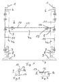
- FIG. 1 shows a view of a conveyor designed as a roller conveyor, which essentially consists of a roller conveyor unit indicated only by its longitudinal members 1 and a support frame 2.
- the longitudinal beam 1 and thus the conveyor is on the support frame 2 on a footprint 3, z. B. a hall floor. It is also fundamentally possible to use the support frame 2 for a hanging arrangement of the conveyor.
- the support frame 2 consists essentially of horizontally and vertically extending profile elements 4a and 4b, which are plugged together via connecting elements 5 to form an H-shaped frame seen in cross section and are then screwed together. Connection plates 6 are screwed to the upper ends of the vertically extending profile elements 4b, on the angled free ends of which the longitudinal members 1 are fastened.
- a connection element 7 is screwed, which has a vertically extending threaded bore 8, into which a support leg 9, which can thereby be adjusted in the vertical direction, is screwed.
- the connecting plates 6 and the connecting elements 7, the profile elements 4a and 4b have depressions 10 in the form of bores. These depressions 10 are arranged in the profile elements 4a and 4b, which are preferably designed as U-profiles, in their web 11. It can be seen from FIG. 1 and there in particular the horizontally extending profile element 4a that the depressions 10 are arranged next to one another with equal spacing and in the longitudinal direction of the profile element 4a one behind the other.
- depressions 10 are designed as elongated holes in order to positively accommodate complementary fitting bodies 12 which are arranged on the connecting elements 7 (see FIG. 2) and the connecting elements 5 (see FIG. 3). This ensures that the connecting elements 5 and the connecting elements 7 can be connected to the profile elements 4a, 4b in a rotationally secure manner.
- FIGS 2 and 3 which is a detailed view of the connecting element 7 and Connection element 5 show, it can be seen that the neck body 12 from a adjacent bearing surface 13 of the connecting element 5 or Connection element 7 protrudes and thus for the positive connection in the Wells 10 can be inserted.
- the side ones are in the inserted state Limits of the attachment body 12 in the form of the bearing surfaces 13 form-fitting the delimitation of the depressions 10 and the web 11 of the profile elements 4a, 4b abuts the bearing surfaces 13.
- the height of the neck body 12 that the height is chosen that this is slightly smaller than the wall thickness of the web 11 of the Profile elements 4a, 4b, so that on the side of the profile elements 4a, 4b supporting head of the screw 14, the support surfaces 13 sufficient to the Inside of the web 11 can be tightened.
- Connecting element 5 and the connecting element 7 are formed as a casting and thus the nut 15 is formed as part of a threaded bore.
- Figure 2 also shows that in addition to the positive connection part, the is formed by the neck body 12, the support surfaces 13 and the nut 15, a connection plate 17 is provided at right angles, in which the Threaded bore 8 for receiving the support foot 9 is arranged.
- connection plates 6 do not have the previously The described positive connection with the elongated depressions 10 are attached because in the present embodiment, these connection plates 6 for Alignment of the longitudinal beams 1 designed to be pivotable about a horizontal axis are and therefore a positive fit is not desirable here.
Abstract
Description
Die Erfindung betrifft ein Traggestell für Förderer, insbesondere für Rollenbahnen
gemäß dem Oberbegriff des Anspruchs 1.The invention relates to a support frame for conveyors, in particular for roller conveyors
according to the preamble of
Aus der deutschen Patentanmeldung DE-4 308 982 - A1 ist bereits ein Rahmengestell für Förderer bekannt, welches aus sich in Förderbandlängsrichtung erstrekkenden Holmen besteht, welche mittels Querverbinder leiterartig miteinander verbunden sind.From German patent application DE-4 308 982 - A1 a frame for conveyors is already known, which extends in the longitudinal direction of the conveyor belt Holmen exists, which by means of cross connectors are connected like a ladder.
Aus der europäischen Patentanmeldung EP 0 623 530 A1 ist bereits ein Traggestell für die Aufhängung eines Hängeförderers bekannt, das im wesentlichen aus stranggepreßten Profilelementen besteht, die über Verbindungselemente zu dem Traggestell zusammenschraubbar sind. Die im Querschnitt rechteckförmigen Profilelemente weisen hierzu an allen Längsseiten und in deren Längsrichtung verlaufende T-förmige Nuten auf, in die hammerkopfförmige Klemmsteine in Form von Schraubenmuttern von oben durch die Öffnung der Nut einlegbar sind. Nach dem Einlegen werden die Klemmsteine innerhalb der Nut um nahezu 90 ° vor deren Befestigung verdreht, damit sich der Klemmstein an den Innenseiten der Hinterschneidungen der Nut abstützen kann. Über die von dem Klemmstein aufgenommene und aus der Nut herausragende Schraube ist somit ein Verbindungselement an einer beliebigen Stelle entlang des Profilelementes anschraubbar. Jedes Verbindungselement weist hierzu eine Bohrung auf, durch die die Schraube des Klemmsteins hindurchgeführt ist. Je nach Ausbildung und Anordnung der mindestens zwei Bohrungen an dem Verbindungselement können die Profilelemente in gewünschten Winkeln zueinander, übereinander und zur Verlängerung hintereinander miteinander verschraubt werden. Als Vorteil dieser Lösung ist angegeben, daß durch die Ausbildung der Verbindungselemente die Ausrichtungen und Positionen der Profilelemente vorab festgelegt werden können, so daß der Einbau wesentlich erleichtert wird. Auch werden durch die durchgehende T-Nut und die unterschiedliche Ausgestaltung der Verbindungselemente eine große Vielfalt an Montagepositionen erreicht. A support frame is already known from European patent application EP 0 623 530 A1 known for the suspension of a overhead conveyor, which essentially consists of extruded profile elements that are connected to the Support frame can be screwed together. The rectangular in cross section For this purpose, profile elements point on all longitudinal sides and in their longitudinal direction running T-shaped grooves on, in the hammer head-shaped terminal blocks in the form of Screw nuts can be inserted from above through the opening in the groove. After this The clamp stones are inserted within the groove by almost 90 ° in front of them Fastening twisted so that the clamp on the inside of the Can undercut the groove. About that of the clamp screw picked up and protruding from the groove is thus a Connection element at any point along the profile element screwed. For this purpose, each connecting element has a bore through which the screw of the clamping block is passed. Depending on training and Arrangement of the at least two holes on the connecting element can Profile elements at the desired angles to each other, one above the other and to Extension screwed together one behind the other. As an advantage of this Solution is indicated that the formation of the connecting elements Alignments and positions of the profile elements can be determined in advance, so that the installation is made considerably easier. Also through the continuous T-slot and the different design of the connecting elements is a big one A variety of mounting positions achieved.
Derartig ausgebildete Traggestelle weisen den Nachteil auf, daß die Profilelemente nur über Klemmkräfte miteinander verbunden sind und somit bezüglich ihrer Belastbarkeit begrenzt sind. Bei Überlastung neigen die Klemmsteine zum Verrutschen in der T-förmigen Nut.Support frames designed in this way have the disadvantage that the profile elements only are connected to each other via clamping forces and thus with regard to their resilience are limited. When overloaded, the clamps tend to slip in the T-shaped Groove.
Desweiteren ist in der europäischen Patentschrift EP 0 611 711 B1 bereits ein Traggestell für einen Bandförderer für Stückgut beschrieben, das im wesentlichen aus horizontal und vertikal verlaufenden Rohrprofilabschnitten besteht, die über Verbindungselemente klemmend miteinander verbunden sind. Über die Verbindungselemente kann jeweils nur ein Anfang oder ein Ende eines Rohrprofils rechtwinklig an einem weiteren Rohrprofil befestigt werden. Das Verbindungselement besteht im wesentlichen aus zwei Klemmbereichen, die über eine Verschraubung an die Rohrprofile andrückbar sind. Der erste Klemmbereich ist nach Art einer einfach geöffneten Rohrschelle ausgebildet, die auf das erste Rohrprofil aufschiebbar ist. Die beiden freien Schenkel des schellenartigen ersten Klemmbereiches sind derartig verlängert und verbreitert ausgebildet, daß in jedem Schenkel eine halbkreisförmige Einbuchtung zur Aufnahme des Anfangs oder Endes des zweiten Rohrprofils angeordnet ist. Seitlich an die halbkreisförmigen Abschnitte anschließend sind in dem Schenkel zusätzlich Bohrungen für Verschraubungen angeordnet, durch die die beiden Klemmbereiche des Verbindungselementes an die Profilrohre andrückbar sind. Gemäß den Ausführungen in der Patentschrift zeichnet sich dieses Traggestell durch eine einfache und kostengünstige Konstruktion aus.Furthermore, there is already one in the European patent specification EP 0 611 711 B1 Support frame for a belt conveyor for general cargo described, which consists essentially of horizontally and vertically extending tubular profile sections, which over Fasteners are clamped together. About the Fasteners can only have one beginning or one end of a pipe profile be attached to another pipe profile at right angles. The connecting element consists essentially of two clamping areas, which are connected by a screw connection the pipe profiles can be pressed on. The first clamping area is a simple one open pipe clamp formed, which can be pushed onto the first pipe profile. The Both free legs of the clamp-like first clamping area are of this type extended and widened that a semicircular in each leg Indentation for receiving the start or end of the second tubular profile is arranged. Laterally to the semicircular sections are in the Legs also arranged holes for screw connections through which the two Clamping areas of the connecting element can be pressed onto the profile tubes. According to the statements in the patent, this support frame is characterized by a simple and inexpensive construction.
Die Ausbildung der Verbindungselemente nach Art einer Rohrschelle mit zwei Klemmbereichen kann sich jedoch als nachteilig erweisen, da über die Schraubverbindung gleichzeitig beide Klemmbereiche an die Rohrprofile angedrückt werden. Hierbei sind jedoch die Klemmkräfte direkt abhängig von den Fertigungstoleranzen des Verbindungselementes und der Rohrprofile, so daß beispielsweise die Klemmkraft an dem ersten Rohrprofilelement vermindert wird, wenn das zweite Rohrprofil einen größeren Durchmesser als vorgesehen aufweist. Eine gleichmäßige Klemmung der beiden Profilrohre ist daher kaum zu erreichen. Darüber hinaus eignen sich auch diese Verbindungselemente, da diese mit Reibschluß arbeiten, nur für begrenzte Belastungen. The design of the connecting elements in the manner of a pipe clamp with two Clamping areas can, however, prove to be disadvantageous because of the Screw connection pressed both clamping areas onto the tube profiles at the same time become. Here, however, the clamping forces are directly dependent on the Manufacturing tolerances of the connecting element and the tube profiles, so that For example, the clamping force on the first tubular profile element is reduced when the second tubular profile has a larger diameter than intended. A Even clamping of the two profile tubes is therefore difficult to achieve. About that In addition, these connecting elements are also suitable, since they have a frictional connection work only for limited loads.
Der vorliegenden Erfindung liegt die Aufgabe zugrunde, ein weiteres Traggestell für Förderer, insbesondere für Rollenbahnen, zu schaffen, das leicht montierbar und kostengünstig ist, sowie sichere Verbindungselemente aufweist.The present invention has for its object a further support frame for To create conveyors, especially for roller conveyors, that are easy to assemble and is inexpensive and has secure connecting elements.
Diese Aufgabe wird bei einem Traggestell für Förderer, insbesondere für Rollenbahnen
durch die im Anspruch 1 aufgeführten Merkmale gelöst. Vorteilhafte Ausgestaltungen
der Erfindung sind in den Unteransprüchen 2 bis 6 angegeben.This task is carried out in a supporting frame for conveyors, in particular for roller conveyors
solved by the features listed in
Erfindungsgemäß wird durch die Ausbildung des Traggestells aus Profilelementen mit Vertiefungen sowie in die Vertiefungen einsteckbaren Verbindungselementen mit komplementär zu den Vertiefungen ausgebildeten Ansatzkörpern, wobei die eingesteckten Verbindungselemente über eine Verschraubung an dem Profilelement gehalten werden, eine konstruktiv einfache Traggestell-Konstruktion geschaffen, die leicht an dem vorgesehenen Aufstellort zu montieren ist. Desweiteren können für einen schnellen Aufbau des Traggestells die benötigten Längen der Profilelemente vorab zugeschnitten werden, so daß für die Montage nur die einzelnen Profilelemente über die Verbindungselemente miteinander verschraubt werden müssen.According to the invention is formed by the formation of the support frame from profile elements Wells and connecting elements that can be inserted into the wells complementary to the recesses formed shoulder bodies, the inserted connecting elements via a screw on the profile element be kept, a structurally simple support structure is created that is easy to install at the intended location. Furthermore, for one the required lengths of the profile elements in advance be cut so that only the individual profile elements for assembly the connecting elements must be screwed together.
Außerdem erweist es sich als besonders vorteilhaft, daß die Steckverbindung zwischen dem Ansatzkörper und der Vertiefung in dem Profilelement formschlüssig ausgebildet ist, da hierdurch das Traggestell im zusammengebauten Zustand eine hohe Festigkeit, insbesondere Standfestigkeit, erhält. Auch werden hierdurch die Lasten zwischen den Profilelementen sicher weitergeleitet. Als konstruktiv besonders einfache Lösung, eine formschlüssige Verbindung zu schaffen, hat sich die Ausbildung der Vertiefungen als langlochförmige Durchgangsbohrungen bewährt, in die hierzu komplementär ausgebildete Ansatzkörper in Form von Paßfedern einsteckbar sind. Darüber hinaus bietet diese Steckverbindung gute Übertragungseigenschaften für die Kräfte quer zur Steckrichtung. Die Sicherung der Verbindung der Profilelemente mit dem Verbindungskörper erfolgt über eine Schraube, die durch eine in dem Ansatzkörper angeordnete Bohrung, die in Steckrichtung ausgerichtet ist, geführt ist und an dem dem Profilelement abgewandten Ende mit einer Mutter versehen ist. Auf der gegenüberliegenden Seite ragt der Schraubenkopf seitlich über den Ansatzkörper hinaus und stützt sich somit auf dem angrenzenden Profilelement ab. It also proves to be particularly advantageous that the connector form-fitting between the neck body and the recess in the profile element is formed, as a result of which the support frame in the assembled state high strength, especially stability. This also means that Loads safely transferred between the profile elements. As constructively special Training has found a simple solution to create a positive connection of the wells proven as elongated through holes, in this Complementally designed neck body in the form of feather keys can be inserted. In addition, this connector offers good transmission properties for the Forces transverse to the direction of insertion. Securing the connection of the profile elements with the connecting body is made via a screw which is inserted in the Approach body arranged bore, which is aligned in the direction of insertion, is guided and is provided with a nut at the end facing away from the profile element. On on the opposite side, the screw head protrudes laterally over the attachment body out and is therefore based on the adjacent profile element.
Als bevorzugt hat sich die Ausbildung der Profilelemente in Form von U-Profilen erwiesen, in deren Steg die Vertiefungen in Längsrichtung der Profilelemente hintereinander sowie voneinander mit gleichem Abstand beabstandet angeordnet sind. Hierdurch ergibt sich eine vorgegebene Teilung, die eine ausreichende Anzahl von Kombinationsmöglichkeiten der Verbindungselemente mit den Profilelementen bietet. Um mindestens zwei Profilelemente miteinander verbinden zu können, weisen die Verbindungselemente mindestens zwei voneinander beabstandete Ansatzkörper auf, an die sich ebene Auflageflächen anschließen. Auf der Auflagefläche wird der Steg des U-profilförmigen Profilelementes abgestützt und durch die Verschraubung auch gehalten. Damit ein ausreichender Anpreßdruck durch die Verschraubung gewährleistet ist, ist -in Steckrichtung gesehen- die Tiefe der langlochförmigen Durchgangsbohrung geringfügig größer gewählt als die Höhe des Ansatzkörpers.The profile elements in the form of U-profiles have proven to be preferred proven in the web of the depressions in the longitudinal direction of the profile elements are arranged one behind the other and at a distance from each other with the same distance. This results in a predetermined division, which is a sufficient number of Combination options of the connecting elements with the profile elements offers. In order to be able to connect at least two profile elements to one another, the Connecting elements at least two spaced-apart shoulder bodies, connect to the level contact surfaces. The web of the U-shaped profile element supported and also by the screw held. So that a sufficient contact pressure through the screw connection is guaranteed - seen in the direction of insertion - the depth of the slot-shaped Through hole chosen slightly larger than the height of the neck body.
Die Erfindung wird nachfolgend anhand von einem in einer Zeichnung dargestellten Ausführungsbeispiel näher beschrieben. Es zeigen:
Figur 1- eine Ansicht eines Traggestells für eine Rollenbahn,
Figur 2- eine Detailansicht eines Verbindungselementes des Traggestells gemäß
Figur 1 und - Figur 3
- eine Ansicht eines Anschlußelementes des Traggestells gemäß
Figur 1.
- Figure 1
- a view of a support frame for a roller conveyor,
- Figure 2
- a detailed view of a connecting element of the support frame according to Figure 1 and
- Figure 3
- a view of a connecting element of the support frame according to Figure 1
Die Figur 1 zeigt eine Ansicht eines als Rollenbahn ausgebildeten Förderers, der im
wesentlichen aus einer nur durch ihre Längsträger 1 angedeuteten Rollen-Fördereinheit
und einem Traggestell 2 besteht. Die Längsträger 1 und somit der
Förderer ist über das Traggestell 2 auf einer Aufstandsfläche 3, z. B. einem
Hallenboden, aufgestellt. Es ist auch grundsätzlich möglich, das Traggestell 2 für eine
hängende Anordnung des Förderers zu verwenden. Das Traggestell 2 besteht im
wesentlichen aus horizontal und vertikal verlaufenden Profilelementen 4a und 4b, die
über Verbindungselemente 5 zu einem im Querschnitt gesehen H-förmigen Rahmen
zusammengesteckt und anschließend verschraubt sind. An die oberen Enden der
vertikal verlaufenden Profilelemente 4b sind Anschlußplatten 6 angeschraubt, auf
deren abgewinkelten freien Enden die Längsträger 1 befestigt sind. An dem
gegenüberliegenden unteren Ende des vertikal verlaufenden Profilelementes 4b ist
ein Anschlußelement 7 angeschraubt, das eine in Vertikalrichtung verlaufende
Gewindebohrung 8 aufweist, in die ein hierdurch in Vertikalrichtung einstellbarer
Stützfuß 9 eingeschraubt ist.
Für die Verschraubung der Profilelemente 4a und 4b mit den Verbindungselementen
5, den Anschlußplatten 6 und den Anschlußelementen 7 weisen die Profilelemente 4a
und 4b Vertiefungen 10 in Form von Bohrungen auf. Diese Vertiefungen 10 sind in
dem vorzugsweise als U-Profile ausgebildeten Profilelementen 4a und 4b in deren
Steg 11 angeordnet. Der Figur 1 und dort insbesondere dem horizontal verlaufenden
Profilelement 4a ist zu entnehmen, daß die Vertiefungen 10 mit gleichen Abständen
nebeneinander sowie in Längsrichtung des Profilelementes 4a hintereinander
angeordnet sind. Diese Vertiefungen 10 sind als Langlöcher ausgebildet um
komplementär paßfederförmig ausgebildete Ansatzkörper 12, die an den
Anschlußelementen 7 (siehe Figur 2) und den Verbindungselementen 5 (siehe Figur 3)
angeordnet sind, formschlüssig aufzunehmen. Hierdurch ist gewährleistet, daß die
Verbindungselemente 5 und die Anschlußelemente 7 verdrehsicher mit den
Profilelementen 4a,4b verbindbar sind.FIG. 1 shows a view of a conveyor designed as a roller conveyor, which essentially consists of a roller conveyor unit indicated only by its
For screwing the
Den Figuren 2 und 3, die eine Detailansicht des Anschlußelementes 7 und des
Verbindungselementes 5 zeigen, ist zu entnehmen, daß der Ansatzkörper 12 aus einer
benachbarten Auflagefläche 13 des Verbindungselementes 5 oder
Anschlußelementes 7 herausragt und somit für die formschlüssige Verbindung in die
Vertiefungen 10 einsteckbar ist. Im eingesteckten Zustand liegen die seitlichen
Begrenzungen der Ansatzkörper 12 in Form der Auflageflächen 13 formschlüssig an
der Begrenzung der Vertiefungen 10 an, sowie der Steg 11 der Profilelemente 4a,4b
an den Auflageflächen 13 anliegt. In dieser eingesteckten Position wird das
Profilelement 4a,4b mit dem Verbindungselement 5 oder dem Anschlußelement 7 über
eine Schraube 14 gehalten, deren Schraubenkopf sich seitlich über den Ansatzkörper
12 erstreckt und sich somit auf dem Steg 11 des Profilelementes 4a,4b abstützt und
die über eine Bohrung 16 in dem Ansatzkörper 12 geführt und durch eine Mutter 15
gehalten wird. Die Mutter 15 stützt sich hierbei an der dem Profilelement 4a,4b
gegenüberliegenden Seite des Verbindungselementes 5 oder des Anschlußelementes
7 ab.Figures 2 and 3, which is a detailed view of the connecting
Ferner ist zu der Ausbildung der Ansatzkörper 12 anzumerken, daß deren Höhe so
gewählt ist, daß diese geringfügig kleiner ist als die Wandstärke des Steges 11 der
Profilelemente 4a,4b, damit über den seitlich auf den Profilelementen 4a,4b sich
abstützenden Kopf der Schraube 14 die Auflageflächen 13 ausreichend an die
Innenseites des Steges 11 angezogen werden können.It should also be noted that the height of the
Den Figuren 2 und 3 ist desweiteren zu entnehmen, daß im vorliegenden Fall das
Verbindungselement 5 und das Anschlußelement 7 als Gußteil ausgebildet sind und
somit die Mutter 15 als Teil einer Gewindebohrung ausgebildet ist.It can also be seen from FIGS. 2 and 3 that in the present case the
Die Figur 2 zeigt außerdem, daß neben dem formschlüssigen Verbindungsteil, das
durch die Ansatzkörper 12, die Auflageflächen 13 und die Mutter 15 gebildet wird,
hierzu rechtwinklig eine Verbindungsplatte 17 vorgesehen ist, in der die
Gewindebohrung 8 zur Aufnahme des Stützfußes 9 angeordnet ist.Figure 2 also shows that in addition to the positive connection part, the
is formed by the
Ergänzend ist der Figur 3 zu entnehmen, daß hier zwei formschlüssige
Verbindungsteile rechtwinklig zueinander angeordnet sind. Zur Verbindung tauchen
beide formschlüssigen Verbindungteile zwischen die Schenkel des U-förmigen
Profilelementes 4a,4b ein und deren Ansatzkörper 12 sind von innen in die
langlochförmigen Bohrungen 10 hindurchsteckbar. Hierdurch werden die
anschraubbaren Profilelemente 4a,4b rechtwinklig zueinander angeordnet.In addition, it can be seen from FIG. 3 that here two form-fitting
Connecting parts are arranged at right angles to each other. Dive to connect
both positive connection parts between the legs of the
Ferner ist der Figur 1 zu entnehmen, daß die Anschlußplatten 6 nicht über die zuvor
beschriebene formschlüssige Verbindung mit den langlochförmigen Vertiefungen 10
befestigt sind, da in der vorliegenden Ausführungsform diese Anschlußplatten 6 zur
Ausrichtung der Längsträger 1 um eine horizontale Achse schwenkbar ausgebildet
sind und somit hier ein Formschluß nicht erwünscht ist. It can also be seen from FIG. 1 that the
- 11
- Längsträgerlongitudinal beams
- 22
- Traggestellsupporting frame
- 33
- Aufstandsflächefootprint
- 4a,b4a, b
- Profilelementeprofile elements
- 55
- Verbindungselementefasteners
- 66
- Anschlußplatteconnecting plate
- 77
- Anschlußelementconnecting element
- 88th
- Gewindebohrungthreaded hole
- 99
- StützfußSupport foot
- 1010
- Vertiefungenwells
- 1111
- Stegweb
- 1212
- Ansatzkörperextension body
- 1313
- Auflageflächebearing surface
- 1414
- Schraubescrew
- 1515
- Muttermother
- 1616
- Bohrungdrilling
- 1717
- Verbindungsplatteconnecting plate
Claims (7)
- Supporting framework for conveyors, in particular for roller conveyors, comprising profile elements (4a, b) which can be screwed to connecting elements (5) in order to be connected to one another, it being the case that the connecting elements (5) have raised extension bodies (12) and the profile elements (4a, b) have depressions (10), the extension body (12) of a connecting element (5) can be plugged in a form-fitting manner into the complementary depression (10) of a profile element (4a, b), in order for the profile element (4a, b) to be connected to the connecting element (5), and the extension body (12) may be retained in the depression (10) via a screw connection (screw 14, nut 15), characterized in that the depressions (10) are designed as slot-like through-passage bores and the extension bodies (12) are in the form of a feather key.
- Supporting framework according to Claim 1, characterized in that exclusively one extension body (12), which can be plugged into a depression (10), is provided for each connection between a profile element (4a, b) and a connecting element (5).
- Supporting framework according to Claim 1 or 2, characterized in that the extension body (12) contains a bore (16) for accommodating a screw (14) for connecting the profile element (4a, b) to the connecting element (5).
- Supporting framework according to one or more of Claims 1 to 3, characterized in that the elongate depressions (10) have their longitudinal extent oriented in the longitudinal direction of the profile elements (4a, b).
- Supporting framework according to one or more of Claims 1 to 4, characterized in that the profile elements (4a, b) are designed as U-profiles, in the web (11) of which the depressions (10) are arranged at equal intervals one behind the other in the longitudinal direction of the profile elements (4a, b).
- Supporting framework according to one or more of Claims 1 to 4, characterized in that the connecting elements (5) have at least two spaced-apart extension bodies (12) which are adjoined by a planar bearing surface (13) for the profile elements (4a, b).
- Supporting framework according to one or more of Claims 3 to 6, characterized in that the depth of the slot-like through-passage bores (cutouts 10) is slightly greater than the height of the extension body (12), in which the screw (14) is arranged, the screw head of the latter being supported, in the fitted state, on that side of the profile element (4a, b) which is directed away from the extension body (12).
Applications Claiming Priority (2)
| Application Number | Priority Date | Filing Date | Title |
|---|---|---|---|
| DE19741663 | 1997-09-16 | ||
| DE19741663A DE19741663C2 (en) | 1997-09-16 | 1997-09-16 | Support frame for conveyors, in particular for roller conveyors |
Publications (2)
| Publication Number | Publication Date |
|---|---|
| EP0909727A1 EP0909727A1 (en) | 1999-04-21 |
| EP0909727B1 true EP0909727B1 (en) | 2003-06-11 |
Family
ID=7843145
Family Applications (1)
| Application Number | Title | Priority Date | Filing Date |
|---|---|---|---|
| EP98250321A Expired - Lifetime EP0909727B1 (en) | 1997-09-16 | 1998-09-10 | Supporting frame for conveyors, especially for roller conveyors |
Country Status (4)
| Country | Link |
|---|---|
| EP (1) | EP0909727B1 (en) |
| AT (1) | ATE242745T1 (en) |
| DE (2) | DE19741663C2 (en) |
| DK (1) | DK0909727T3 (en) |
Families Citing this family (3)
| Publication number | Priority date | Publication date | Assignee | Title |
|---|---|---|---|---|
| US20020066647A1 (en) * | 2000-12-05 | 2002-06-06 | Mctaggart Michael Douglas | Modular roller conveyor system |
| EP1338533B1 (en) * | 2002-02-26 | 2004-12-22 | FPS Food Processing Systems B.V. | Conveyor frame |
| CN105059833A (en) * | 2015-07-15 | 2015-11-18 | 苏州柏德纳科技有限公司 | Part limit delivery device |
Family Cites Families (11)
| Publication number | Priority date | Publication date | Assignee | Title |
|---|---|---|---|---|
| GB696224A (en) * | 1950-09-12 | 1953-08-26 | Marconi Wireless Telegraph Co | Improvements in or relating to cabinets for radio apparatus |
| DE1797649U (en) * | 1959-07-04 | 1959-10-08 | Bruno Hartmann | BAN CONVEYOR WITH A LIGHTWEIGHT CONSTRUCTION. |
| DE1456688A1 (en) * | 1966-06-23 | 1969-03-27 | Und Eisengiesserei A Beien Mas | Continuous conveyor with an endless, revolving conveyor belt |
| CH585140A5 (en) * | 1974-08-27 | 1977-02-28 | Masyc Ag | |
| US4172677A (en) * | 1974-08-27 | 1979-10-30 | Masyc Ag | Variable load-bearing framework |
| DE7615311U1 (en) * | 1976-05-14 | 1976-09-09 | Gustav Schade Maschinenfabrik, 4600 Dortmund | CONVEYOR BELT, IN PARTICULAR STORAGE CONVEYOR FOR LAYING IN A CONVEYOR CHANNEL OR A CONVEYOR BRIDGE IN A BUCKET PACKAGE |
| DE4304555C1 (en) * | 1993-02-16 | 1994-08-04 | Khs Masch & Anlagenbau Ag | Connection piece for the clamping connection of two perpendicularly arranged profile pieces of a conveyor frame |
| DE4308982C2 (en) * | 1993-03-20 | 1994-12-15 | Mtf Technik Ing Grad Hans Gert | Conveyor belt |
| DE4308980A1 (en) * | 1993-03-20 | 1994-07-14 | Mtf Technik Ing Grad Hans Gert | Edging strip for conveyor belt |
| DE9306657U1 (en) * | 1993-05-03 | 1994-09-22 | Rsl Logistik Gmbh & Co | Overhead conveyor with a mounting profile set |
| US5421451A (en) * | 1994-03-02 | 1995-06-06 | Alvey, Inc. | Conveyor construction |
-
1997
- 1997-09-16 DE DE19741663A patent/DE19741663C2/en not_active Expired - Fee Related
-
1998
- 1998-09-10 AT AT98250321T patent/ATE242745T1/en not_active IP Right Cessation
- 1998-09-10 EP EP98250321A patent/EP0909727B1/en not_active Expired - Lifetime
- 1998-09-10 DK DK98250321T patent/DK0909727T3/en active
- 1998-09-10 DE DE59808680T patent/DE59808680D1/en not_active Expired - Fee Related
Also Published As
| Publication number | Publication date |
|---|---|
| DE19741663A1 (en) | 1999-03-25 |
| DE19741663C2 (en) | 1999-08-19 |
| DE59808680D1 (en) | 2003-07-17 |
| EP0909727A1 (en) | 1999-04-21 |
| ATE242745T1 (en) | 2003-06-15 |
| DK0909727T3 (en) | 2003-09-22 |
Similar Documents
| Publication | Publication Date | Title |
|---|---|---|
| EP0452256B1 (en) | Angular connection of two profiles with a c-shaped prolongation using a connector and an angular element for assembling the connection | |
| DE2618442C2 (en) | Support for a railing or the like | |
| EP2099971B1 (en) | Railway joint connection arrangement | |
| DE202012012290U1 (en) | Fastening device for fastening plate-shaped components | |
| CH682004A5 (en) | ||
| DE2504476A1 (en) | Fixture for polygonal building strut - has one leg of pair tilted under screw force to clamp strut | |
| EP0004374A1 (en) | Device for joining two profiled bars | |
| EP0909727B1 (en) | Supporting frame for conveyors, especially for roller conveyors | |
| EP1388620B1 (en) | Connection element for a mounting system | |
| DE20321415U1 (en) | Support framework for a facade | |
| EP0423474B1 (en) | Device for the releasable fastening of two profiled rods | |
| EP0623530A1 (en) | Overhead conveyor system with a set of profiling strips for mounting | |
| DE4439864C2 (en) | Fastening arrangement for tabular components | |
| EP0141211B1 (en) | Rail for a monorail suspension track | |
| DE4447208A1 (en) | Floor carrier system with wall mounted holding rail | |
| EP0876788A2 (en) | U-shaped profile, with wall support, for a partition | |
| DE4218413C2 (en) | Device for fastening plate-shaped facade elements | |
| EP0903505A1 (en) | Element for fastening in a cavity of a profile or similar workpiece | |
| EP3546767B1 (en) | Construction kit system and connector for profiles of a construction kit system | |
| DE3432140C2 (en) | Formwork element | |
| EP0818592A1 (en) | Reinforcing system | |
| DE102020106891B4 (en) | T-connection between a mullion and transom profile and a mullion-transom construction with such a T-connection | |
| DE19503429B4 (en) | Device for the frontal connection of cable runs | |
| DE4303935A1 (en) | Cross-type connector | |
| DE3113786A1 (en) | Adjustable suspension arrangement for support rails |
Legal Events
| Date | Code | Title | Description |
|---|---|---|---|
| PUAI | Public reference made under article 153(3) epc to a published international application that has entered the european phase |
Free format text: ORIGINAL CODE: 0009012 |
|
| AK | Designated contracting states |
Kind code of ref document: A1 Designated state(s): AT DE DK FR GB IT NL |
|
| AX | Request for extension of the european patent |
Free format text: AL;LT;LV;MK;RO;SI |
|
| 17P | Request for examination filed |
Effective date: 19990415 |
|
| AKX | Designation fees paid |
Free format text: AT DE DK FR GB IT NL |
|
| RAP1 | Party data changed (applicant data changed or rights of an application transferred) |
Owner name: SIEMENS AKTIENGESELLSCHAFT |
|
| GRAH | Despatch of communication of intention to grant a patent |
Free format text: ORIGINAL CODE: EPIDOS IGRA |
|
| GRAH | Despatch of communication of intention to grant a patent |
Free format text: ORIGINAL CODE: EPIDOS IGRA |
|
| GRAA | (expected) grant |
Free format text: ORIGINAL CODE: 0009210 |
|
| AK | Designated contracting states |
Designated state(s): AT DE DK FR GB IT NL |
|
| REG | Reference to a national code |
Ref country code: GB Ref legal event code: FG4D Free format text: NOT ENGLISH |
|
| REF | Corresponds to: |
Ref document number: 59808680 Country of ref document: DE Date of ref document: 20030717 Kind code of ref document: P |
|
| PG25 | Lapsed in a contracting state [announced via postgrant information from national office to epo] |
Ref country code: AT Free format text: LAPSE BECAUSE OF NON-PAYMENT OF DUE FEES Effective date: 20030910 |
|
| PG25 | Lapsed in a contracting state [announced via postgrant information from national office to epo] |
Ref country code: GB Free format text: LAPSE BECAUSE OF NON-PAYMENT OF DUE FEES Effective date: 20030911 |
|
| REG | Reference to a national code |
Ref country code: DK Ref legal event code: T3 |
|
| PG25 | Lapsed in a contracting state [announced via postgrant information from national office to epo] |
Ref country code: DK Free format text: LAPSE BECAUSE OF NON-PAYMENT OF DUE FEES Effective date: 20030930 |
|
| GBT | Gb: translation of ep patent filed (gb section 77(6)(a)/1977) |
Effective date: 20031007 |
|
| ET | Fr: translation filed | ||
| PG25 | Lapsed in a contracting state [announced via postgrant information from national office to epo] |
Ref country code: NL Free format text: LAPSE BECAUSE OF NON-PAYMENT OF DUE FEES Effective date: 20040401 Ref country code: DE Free format text: LAPSE BECAUSE OF NON-PAYMENT OF DUE FEES Effective date: 20040401 |
|
| PLBE | No opposition filed within time limit |
Free format text: ORIGINAL CODE: 0009261 |
|
| STAA | Information on the status of an ep patent application or granted ep patent |
Free format text: STATUS: NO OPPOSITION FILED WITHIN TIME LIMIT |
|
| GBPC | Gb: european patent ceased through non-payment of renewal fee |
Effective date: 20030911 |
|
| REG | Reference to a national code |
Ref country code: DK Ref legal event code: EBP |
|
| NLV4 | Nl: lapsed or anulled due to non-payment of the annual fee |
Effective date: 20040401 |
|
| 26N | No opposition filed |
Effective date: 20040312 |
|
| PG25 | Lapsed in a contracting state [announced via postgrant information from national office to epo] |
Ref country code: IT Free format text: LAPSE BECAUSE OF NON-PAYMENT OF DUE FEES;WARNING: LAPSES OF ITALIAN PATENTS WITH EFFECTIVE DATE BEFORE 2007 MAY HAVE OCCURRED AT ANY TIME BEFORE 2007. THE CORRECT EFFECTIVE DATE MAY BE DIFFERENT FROM THE ONE RECORDED. Effective date: 20050910 |
|
| PG25 | Lapsed in a contracting state [announced via postgrant information from national office to epo] |
Ref country code: FR Free format text: LAPSE BECAUSE OF NON-PAYMENT OF DUE FEES Effective date: 20030930 |
|
| REG | Reference to a national code |
Ref country code: FR Ref legal event code: ST Effective date: 20110923 |