EP0907192B1 - Stufenschalter - Google Patents
Stufenschalter Download PDFInfo
- Publication number
- EP0907192B1 EP0907192B1 EP98116517A EP98116517A EP0907192B1 EP 0907192 B1 EP0907192 B1 EP 0907192B1 EP 98116517 A EP98116517 A EP 98116517A EP 98116517 A EP98116517 A EP 98116517A EP 0907192 B1 EP0907192 B1 EP 0907192B1
- Authority
- EP
- European Patent Office
- Prior art keywords
- contacts
- phase
- tap changer
- movable
- insulating shaft
- Prior art date
- Legal status (The legal status is an assumption and is not a legal conclusion. Google has not performed a legal analysis and makes no representation as to the accuracy of the status listed.)
- Expired - Lifetime
Links
- 230000000903 blocking effect Effects 0.000 claims description 11
- 241000282472 Canis lupus familiaris Species 0.000 claims 1
- 239000000969 carrier Substances 0.000 abstract description 2
- 241000549194 Euonymus europaeus Species 0.000 abstract 1
- 238000004804 winding Methods 0.000 description 5
- 210000003746 feather Anatomy 0.000 description 3
- 230000005540 biological transmission Effects 0.000 description 2
- 238000009795 derivation Methods 0.000 description 2
- 238000002955 isolation Methods 0.000 description 2
- 238000004519 manufacturing process Methods 0.000 description 2
- 238000010079 rubber tapping Methods 0.000 description 2
- 239000004020 conductor Substances 0.000 description 1
- 238000010276 construction Methods 0.000 description 1
- 238000011109 contamination Methods 0.000 description 1
- 230000001419 dependent effect Effects 0.000 description 1
- 238000011161 development Methods 0.000 description 1
- 230000018109 developmental process Effects 0.000 description 1
- 230000003628 erosive effect Effects 0.000 description 1
- 238000000034 method Methods 0.000 description 1
Images


Classifications
-
- H—ELECTRICITY
- H01—ELECTRIC ELEMENTS
- H01H—ELECTRIC SWITCHES; RELAYS; SELECTORS; EMERGENCY PROTECTIVE DEVICES
- H01H9/00—Details of switching devices, not covered by groups H01H1/00 - H01H7/00
- H01H9/0005—Tap change devices
- H01H9/0038—Tap change devices making use of vacuum switches
-
- H—ELECTRICITY
- H01—ELECTRIC ELEMENTS
- H01H—ELECTRIC SWITCHES; RELAYS; SELECTORS; EMERGENCY PROTECTIVE DEVICES
- H01H9/00—Details of switching devices, not covered by groups H01H1/00 - H01H7/00
- H01H9/0005—Tap change devices
- H01H9/0027—Operating mechanisms
- H01H9/0033—Operating mechanisms with means for indicating the selected tap or limiting the number of selectable taps
-
- H—ELECTRICITY
- H01—ELECTRIC ELEMENTS
- H01H—ELECTRIC SWITCHES; RELAYS; SELECTORS; EMERGENCY PROTECTIVE DEVICES
- H01H3/00—Mechanisms for operating contacts
- H01H3/32—Driving mechanisms, i.e. for transmitting driving force to the contacts
- H01H3/44—Driving mechanisms, i.e. for transmitting driving force to the contacts using Geneva movement
Definitions
- the invention relates to a tap changer based on the reactor switching principle uninterrupted load switching using vacuum switch cells.
- a tap changer is used in conjunction with a power transformer uninterrupted switching between different winding taps uses this transformer and thus serves for uninterrupted Voltage regulation.
- the invention relates to tap changers according to the reactor switching principle mentioned first.
- Such a tap changer is already known from the company publication "Load Tap Changer Type RMV II” from Reinhausen Manufacturing, Humboldt, Tenessee, USA, imprint RM 05/91 - 1094/5000.
- vacuum switching cells are used for the actual load switching, which have numerous advantages over mechanical load switching contacts, in particular also a long service life.
- vacuum switching cells there is no contamination of the surrounding oil, which would occur in mechanical load changeover contacts due to arcing and contact erosion.
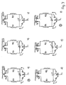
- FIG. 7 shows the typical sequence of such a known step switch of the generic type when switching from one step A to an adjacent step B for one phase.
- N and n + 1 are adjacent taps of the tap winding of the transformer.
- P1 and P2 are the movable selector contacts to be actuated during the switchover, R1 and R2 are the switchover impedances already explained.
- a vacuum switching cell V is connected between the two branches, and the corresponding connection to the load conductor L is established by a by-pass contact B.
- the two movable selector contacts are both on the same tap, ie on the same fixed selector contact.
- one movable selector contact rests on a first fixed selector contact and the other movable selector contact on the adjacent further fixed selector contact. This sequence is repeated with every further load changeover.
- the known tap changer is designed in three phases and consists of an oil-filled housing that has selector contacts, preselector contacts, vacuum switching cells and by-pass contacts.
- the term “preselector contacts” is intended to mean both the contacts for a possible coarse selector and for a possible turner. These two circuit variants are well known from the prior art.
- the drive mechanism for actuating the individual contacts and the vacuum switch cells is located in a housing part which is arranged on the side of the housing.
- a terminal board is provided in the housing, on which the selector and reversing contacts are arranged, spatially separated for each of the three phases to be switched.
- the corresponding vacuum switch cell and the associated by-pass contacts for each phase are arranged on further boards in the following way:
- the fixed and the movable by-pass contact On one side of the other board, which faces the terminal board, are the fixed and the movable by-pass contact, on the other side of the board is the vacuum switch cell, each with an energy accumulator for its actuation.
- a corresponding energy store is known from DE 4126 824.
- All switching elements of all phases are actuated by a single insulating shaft, which is from the drive mechanism located in the side housing part, the entire housing passes.
- three Maltese drives are provided, one for each phase are also provided on the terminal board. These Maltese drives generate from the rotational movement of the drive shaft, both the movements for actuation the selector and reversing contacts as well as the movements for actuating the by-pass contacts and the tensioning of the energy accumulator to actuate the corresponding one Vacuum switch cells in the predetermined switching sequence, as shown in Fig. 1.
- a single insulating shaft actuates three separate Maltese drives.
- Each Maltese drive in turn actuates the elements of the respective phase arranged on the terminal board, namely the selector contacts and, by means of a separate bolt on the Maltese, the reversing contacts.
- the elements of the respective phase namely the by-pass contact and the energy accumulator of the corresponding vacuum switching cell, are actuated by means of a double-sided groove in a rotatable disc.
- Such a disk provided with a double-sided control contour is known from DE 40 11 019 known.
- the object of the invention is to simplify the generic tap changer and the number of necessary parts, especially the number of necessary parts Maltese drives to reduce. It is also an object of the invention to actuate the by-pass contacts on the one hand and the vacuum switch cells on the other hand to simplify and, in connection with this standing to indicate a simple, yet safe functioning energy store.
- Another advantage is the particularly simple design of the energy store for actuating the respective vacuum switch cell, which nevertheless ideally fulfills the desired switching characteristics for such cells:
- the vacuum switch cell is opened quickly by means of the energy store and closed in a curve-controlled manner.
- a further advantage lies in the simple mechanical end position limitation, which is provided only once in the single gearbox and which prevents the selector contacts from advancing beyond the permissible switching range. Corresponding necessary end position limits are no longer required on the respective phase plates.
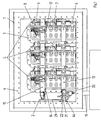
- the tap changer according to the invention is enclosed by an oil-tight housing 1, the front, removable front side 4 of which is open here.
- On the back of the housing 1 there are lead-through plates 3 for oil-tight routing of the connecting lines, not shown.
- On the left wall there is a gear plate 2, which has the only Maltese drive, to be explained in more detail, for actuating the selector and preselector contacts, and a drive mechanism, which is also explained in more detail, for actuating the by-pass contacts and the vacuum switching cells.
- three phase plates 5 - one for each phase to be switched - are provided.
- On the right side of each phase plate 5 are the circularly arranged fixed selector contacts 6, which can be connected by a rotatable, centrally arranged movable contact carrier 7 on which there are two movable selector contacts 7.1, 7.2.
- Both movable selector contacts 7.1, 7.2 are isolated from each other on the Contact carrier 7 arranged and are moved together by its rotation. Furthermore, the fixed selection contacts 8 are located on this side, by a movable contact carrier 9 can be connected, on which there is a movable Selector contact 9.1 is located.
- the fixed by-pass contacts are also located on this page 10, which can be connected by a further contact carrier 11, on the there are two by-pass contacts 11.1, 11.2. Both movable by-pass contacts 11.1, 11.2 are electrically connected to one another.
- the vacuum switch cell 12 On the left side of the phase plate 5 is the vacuum switch cell 12 with the corresponding actuation mechanism, which will be discussed in more detail below becomes.
- three horizontal insulating shafts 13, 14, 15 lead through the entire housing 1. They penetrate all three phase plates 5, in which bores 16, 17, 18 are provided for this purpose.
- the first insulating shaft 13 is guided through the bore 16 of the phase plate 5 and is in each case connected to the contact carrier 7 and thus to the movable selector contacts 7.1, 7.2 of each phase.
- the second insulating shaft 14, which is partially covered in FIG. 1, is guided through the bore 17 of the phase plate 5 and is connected to the contact carrier 9 and thus to the movable preselector contact 9.1 of each phase.
- the third insulating shaft 15 is guided through the bore 18 of each phase plate 5 and is connected to the contact carrier 11 and thus the movable by-pass contacts 11.1, 11.2 and the corresponding vacuum switching cell 12 of each phase.
- the first insulating shaft 13 thus actuates the movable selector contacts 7.1, 7.2 of each phase, which connect the associated fixed selector contacts 6.
- the second insulating shaft 14 actuates the movable selector contact 9.1 of each phase, which connects the associated fixed selector contacts 8.
- the third insulating shaft 15 finally actuates the movable by-pass contacts 11.1, 11.2 of each phase, which connect the fixed by-pass contacts 10, and the respective vacuum switching cell 12 of each phase.
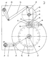
- the insulating shafts 13, 14, 15 in turn are made from the only one arranged on the left in FIG. 1 Maltese drive and the other components arranged on the transmission plate 2 are operated together.
- All three insulating shafts 13, 14, 15 are rotatably supported independently of one another and spatially separated in the gear plate.
- a drive shaft 19 leads from a drive (not shown in detail) into the housing 1 from below.
- a first gear wheel 20 which corresponds to a second gear wheel 21 which is perpendicular thereto.
- This second gear wheel 21 is mounted in a bearing 22 in the gear plate 2 and is firmly connected to a Maltese driver 23, which has a roller 24 at its end.
- a third gear wheel 25 which in turn is also mounted in a further bearing 51 in the gear plate 2.
- a rocker arm 26 is fastened, which leads to a rotatably articulated lever 27, the other free end of which is in turn rotatably articulated to a further rocker arm 28, which is fastened on the insulating shaft 15.
- a thrust crank mechanism known per se is thus realized.
- a Geneva wheel 29 is fastened on the insulating shaft 13 in such a way that the cutouts in the Geneva wheel 29 interact with the roller 24 of the Geneva driver 23.
- a single actuating roller 30 is also provided, which engages in a certain position of the Geneva wheel 29 in a pivotable lever 31 which is connected to the insulating shaft 14.
- This drive works as follows: When the tap changer is actuated, the drive shaft 19 rotates; this rotation is transmitted to the second gear wheel 21 via the first gear wheel 20.
- the Maltese driver 23, whose roller 24 engages in the Maltese wheel 29, rotates it by a certain angle, which depends on the dimensioning of this Maltese wheel 29 and the incisions located thereon, and thus also rotates the associated insulating shaft 13 by one switching step ,
- the dimensioning mentioned is designed so that when the Geneva wheel 29 is rotated completely, all fixed selector contacts 6 are swept over. With each switching, the movable selector contacts 7.1, 7.2 of each phase are switched from one fixed selector contact to the other neighboring selector contact - depending on the direction of rotation.
- the rotary movement is transmitted to the third gear wheel 25 and thus to the rocker 26.
- the gear wheels are dimensioned such that the third gear wheel 25 rotates by 180 degrees with each changeover.
- the rocker arm 26 rotates, the further rocker arm 28 and thus the isolating shaft 15 are rotated through the lever 27 through a certain angle and then back into the starting position.
- the movable by-pass contacts 11.1, 11.2 of each phase are briefly deflected from the end position and opened and then moved back into the end position.
- the isolating shaft 15 While the isolating shaft 13 rotates through a certain angle in the same direction in each circuit and can therefore make complete rotations, the isolating shaft 15 always rotates alternately to the left or right by an angle and back again and transmits this movement to the oscillating movable by-pass contacts 11.1, 11.2 swiveling out of the middle position into an end position and back again.
- the roller 30 arranged on the Geneva wheel 29, which engages in a certain position in a cutout of the lever 31 this is then pivoted by a certain angle and with it the insulating shaft 14, which actuates the movable preselector contact 9.1 of each phase. The selection is therefore only activated after a complete rotation of the Geneva wheel 29 and thus after all fixed selector contacts 6 have been run through.
- the Geneva wheel 29 can rotate completely once, running through all the fixed selector contacts 6 without the selection being activated, then this is actuated and all the fixed selector contacts 6 can be run through again in the same direction of rotation with the selection selected. Similarly, the selection is switched back after a complete rotation in another direction.
- FIG. 3 shows once again the arrangement of the different fixed and movable contacts explained on the respective phase plate 5 and their actuation by the insulating shafts 13, 14, 15.
- the movable selector contacts 7.1, 7.2 which are insulated from one another, are dimensioned such that they can both contact two adjacent fixed selector contacts 6, or can rest completely on only one such contact, as is necessary to implement the switching sequence shown in FIG. 7.
- the movable selector contact 9.1 switches after one revolution of the Maltese wheels 29 from one position to the other and thus switches part of one Winding up or down or deflecting this depends on whether the selection is in the respective circuit of the step transformer as a known coarse selector or well-known turner works. Result for the tap changer according to the invention there are no differences in the construction.
- the movable, electrically connected by-pass contacts 11.1, 11.2 bridge both fixed contacts 10 in the stationary state and are in the Switching together on only one of these fixed contacts 10
- the contact derivation from the movable, rotatable contacts 7.1, 7.2; 9.1; 11.1, 11.2 takes place in each case through concentric slip rings 32, 33, 34
- Contact derivation of the two movable selector contacts 7.1, 7.2 two, from each other Insulated slip rings 32 are provided, which are congruent with one another in FIG lying so that only the top of them can be seen.
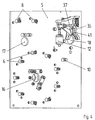
- FIG. 4 shows the elements arranged on the other side of the respective phase plate 5 without insulating shafts
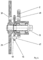
- FIG. 5 again shows the elements for actuating the respective vacuum switch cell 12, which are to be explained in more detail below.
- a console 35 is attached to each phase plate 5 and supports the vacuum switch cell 12.
- the actuating mechanism consists of a control disk 36 which is connected to the insulating shaft 15 and a two-armed lever 37 which is rotatably mounted on the bracket 35 and has a roller 38 at one free end and the other free end of the vacuum switchgear cell 12, more precisely its actuating plunger 45, works.
- the roller 38 corresponds to a control cam 39 on the control disk 36.
- a release contour 40 which is dimensioned such that it deflects a pawl 41 in certain positions of the control disk 36.
- This triggering contour 40 can be realized particularly advantageously by means of two individual triggering cams.
- the lever 37 is then released by the deflected pawl 41, which is otherwise blocked by the non-deflected pawl 41.
- a spring 42 is supported on the bracket 35 and presses the roller 38 of the lever 37 against the cam 39.
- Another spring 43 presses the pawl 41 against the lever 37 and blocks it in the normal state.
- a third spring 44 on the actuating plunger 45 increases the contact pressure in the stationary state and is not absolutely necessary for actuation.
- the lever 37 is suddenly released and also opens the vacuum switching cell 12 suddenly with the spring 42.
- the insulating shaft 15 then rotates and with it the control disk 36 again.
- the roller 38 runs on the cam 39 and closes the vacuum switching cell 12 continuously.
- the pawl 41 engages again on the lever 37 and blocks it; the end position and at the same time the starting position for the next switchover has been reached.
- the first driver 47 corresponds to a fixed stop 49 on the transmission plate 2
- the second driver 48 corresponds to at least one further driver 50 on the Geneva wheel 29. It is particularly advantageous to implement the two carriers 47 and 48 by means of a single cylindrical pin which penetrates the blocking disk 46.
- the mode of action is as follows:
- the Geneva wheel 29 can initially rotate in each direction by one turn until the driver 50 meets the driver 48, with the further rotation in the same direction the blocking disk 46 is also rotated. If this has rotated by one revolution, the driver 47 hits the stop 49 and blocks both the blocking disc 46 and the Geneva wheel 29, which then has undergone two revolutions - the end position has been reached.
- the process is repeated analogously - the floating blocking disk 46 allows two revolutions of the Geneva wheel 29 in both directions, during which all fixed selector contacts 6 are swept twice - once with and once without a selection.
- driver 50 If there is only one driver 50, this can be of any shape or size be dimensioned. This makes it possible to easily Limit of end position to the permissible revolutions defined above, which are not quite correspond to a full rotation of 360 degrees, but in each case of the two Switching steps corresponding angles are missing to adjust.
Landscapes
- Driving Mechanisms And Operating Circuits Of Arc-Extinguishing High-Tension Switches (AREA)
- High-Tension Arc-Extinguishing Switches Without Spraying Means (AREA)
- Housings And Mounting Of Transformers (AREA)
- Transmission Devices (AREA)
- Mechanically-Actuated Valves (AREA)
- Manufacture Of Switches (AREA)
- Mechanisms For Operating Contacts (AREA)
- Valve Device For Special Equipments (AREA)
- Amplifiers (AREA)
- Electrophonic Musical Instruments (AREA)
- Lock And Its Accessories (AREA)
Applications Claiming Priority (2)
| Application Number | Priority Date | Filing Date | Title |
|---|---|---|---|
| DE19743864A DE19743864C1 (de) | 1997-10-04 | 1997-10-04 | Stufenschalter |
| DE19743864 | 1997-10-04 |
Publications (3)
| Publication Number | Publication Date |
|---|---|
| EP0907192A2 EP0907192A2 (de) | 1999-04-07 |
| EP0907192A3 EP0907192A3 (de) | 2000-03-08 |
| EP0907192B1 true EP0907192B1 (de) | 2004-01-28 |
Family
ID=7844577
Family Applications (1)
| Application Number | Title | Priority Date | Filing Date |
|---|---|---|---|
| EP98116517A Expired - Lifetime EP0907192B1 (de) | 1997-10-04 | 1998-09-01 | Stufenschalter |
Country Status (6)
| Country | Link |
|---|---|
| US (1) | US6060669A (enExample) |
| EP (1) | EP0907192B1 (enExample) |
| JP (1) | JP4235290B2 (enExample) |
| AT (1) | ATE258713T1 (enExample) |
| CA (1) | CA2249115C (enExample) |
| DE (2) | DE19743864C1 (enExample) |
Families Citing this family (42)
| Publication number | Priority date | Publication date | Assignee | Title |
|---|---|---|---|---|
| DE19720617C2 (de) * | 1997-05-16 | 1999-03-18 | Reinhausen Maschf Scheubeck | Stellungsmeldeanordnung für Motorantriebe |
| US6693247B1 (en) | 2000-06-09 | 2004-02-17 | Mcgraw-Edison Company | Load tap changer with direct drive and brake |
| US6781070B1 (en) * | 2003-01-29 | 2004-08-24 | Herker Industries, Inc. | Indexing rotary switch |
| US7463010B2 (en) | 2003-04-03 | 2008-12-09 | Maschinenfabrik Reinhausen Gmbh | Multipoint switch |
| US7614357B2 (en) * | 2003-09-08 | 2009-11-10 | Cooper Technologies Company | Step voltage regulator polymer position indicator with non-linear drive mechanism |
| JP2007515744A (ja) * | 2003-09-13 | 2007-06-14 | アーベーベー・テヒノロギー・アーゲー | 電動式スイッチング装置を作動させるための装置 |
| US7750257B2 (en) * | 2004-06-03 | 2010-07-06 | Cooper Technologies Company | Molded polymer load tap changer |
| CA2748578A1 (en) * | 2008-12-29 | 2010-07-08 | Abb Technology Ag | An improved reversing switch and a method of retrofitting |
| DE102009043171B4 (de) * | 2009-09-26 | 2014-11-20 | Maschinenfabrik Reinhausen Gmbh | Stufenschalter mit Vakuumschaltröhren |
| MX2013011028A (es) | 2011-03-25 | 2014-03-31 | Abb Technology Ag | Cambiador de toma con un montaje interruptor de vacio con amortiguador mejorado. |
| CN103548106B (zh) | 2011-03-25 | 2017-02-08 | Abb技术有限公司 | 具有改进的真空断续器致动组件的分接头变换器 |
| WO2012134958A1 (en) * | 2011-03-25 | 2012-10-04 | Abb Technology Ag | An improved tap changer |
| EP2691967B1 (en) | 2011-03-27 | 2017-03-01 | ABB Technology AG | Tap changer with an improved drive system |
| WO2012135213A1 (en) * | 2011-03-27 | 2012-10-04 | Abb Technology Ag | Tap changer with an improved monitoring system |
| DE102011119318B4 (de) * | 2011-11-23 | 2014-11-27 | Maschinenfabrik Reinhausen Gmbh | Stufenschalter mit Vakuumschaltröhren |
| EP2637185B1 (en) | 2012-03-06 | 2014-01-15 | ABB Technology Ltd | A tap changer and a method related thereto |
| CN103426657B (zh) * | 2012-05-17 | 2016-03-30 | 上海华明电力设备制造有限公司 | 一种分接选择器动触头与静触头之间的切换结构 |
| DE102012104378B4 (de) * | 2012-05-22 | 2015-09-17 | Maschinenfabrik Reinhausen Gmbh | Anordnung von Vakuumschaltröhren bei einem Lastumschalter |
| BR112015022525A2 (pt) | 2013-03-15 | 2017-07-18 | Cooper Technologies Co | sistema de comutação de toque e subconjunto de comutação para um sistema de comutação de toque |
| DE102013103360A1 (de) * | 2013-04-04 | 2014-10-09 | Maschinenfabrik Reinhausen Gmbh | Verfahren zur Durchführung eines Umschaltvorgangs in einem Laststufenschalter |
| CN103400715B (zh) * | 2013-08-08 | 2015-09-30 | 贵州长征电气有限公司 | 多档位位置信号传送装置 |
| DE102013109611A1 (de) * | 2013-09-03 | 2015-03-05 | Maschinenfabrik Reinhausen Gmbh | Vorrichtung und Verfahren zur Steuerung der Stabilität eines Ortsnetzes mit einem regelbaren Ortsnetztransformator |
| USD759668S1 (en) * | 2014-01-13 | 2016-06-21 | Samsung Electronics Co., Ltd. | Display screen or portion thereof with graphical user interface |
| CN204257438U (zh) * | 2014-12-29 | 2015-04-08 | 刁俊起 | 一种永磁驱动有载调压开关 |
| DE102015106178A1 (de) * | 2015-04-22 | 2016-10-27 | Maschinenfabrik Reinhausen Gmbh | Laststufenschalter |
| DE102015225314A1 (de) * | 2015-12-15 | 2017-06-22 | Siemens Aktiengesellschaft | Regelbarer Ortsnetztransformator |
| DE102016104499B3 (de) | 2016-03-11 | 2017-04-27 | Maschinenfabrik Reinhausen Gmbh | Wähler für einen Laststufenschalter und Laststufenschalter mit Lastumschalter und Wähler |
| DE102016104500B3 (de) * | 2016-03-11 | 2017-05-04 | Maschinenfabrik Reinhausen Gmbh | Laststufenschalter |
| US9679710B1 (en) | 2016-05-04 | 2017-06-13 | Cooper Technologies Company | Switching module controller for a voltage regulator |
| DE102016117526B3 (de) | 2016-09-16 | 2018-02-15 | Maschinenfabrik Reinhausen Gmbh | Lasststufenschalter, Regeltransformator mit Laststufenschalter und Verfahren zum Schalten eines Laststufenschalters |
| CN106847609A (zh) * | 2017-02-10 | 2017-06-13 | 山东民生电气设备有限公司 | 一种用于有载调压开关的小型化切换开关组件 |
| CN106601516A (zh) * | 2017-02-10 | 2017-04-26 | 山东民生电气设备有限公司 | 一种用于有载调压开关的小型化选择开关组件 |
| DE102018105097A1 (de) | 2018-03-06 | 2019-09-12 | Maschinenfabrik Reinhausen Gmbh | Laststufenschalter und ortsnetztransformator mit einem laststufenschalter |
| DE102018113982B4 (de) * | 2018-06-12 | 2023-09-28 | Maschinenfabrik Reinhausen Gmbh | Laststufenschalter und verfahren zur betätigung eines laststufenschalters |
| DE102019130460A1 (de) * | 2019-11-12 | 2021-05-12 | Maschinenfabrik Reinhausen Gmbh | Laststufenschalter |
| DE102019130462B4 (de) | 2019-11-12 | 2022-03-24 | Maschinenfabrik Reinhausen Gmbh | Wähler für Laststufenschalter sowie Laststufenschalter damit |
| DE102019131169B3 (de) * | 2019-11-19 | 2021-02-18 | Maschinenfabrik Reinhausen Gmbh | Laststufenschalter und Stufentransformator mit Laststufenschalter |
| DE102020122450A1 (de) | 2020-08-27 | 2022-03-03 | Maschinenfabrik Reinhausen Gmbh | Schaltmodul und Laststufenschalter mit Schaltmodul |
| EP3989253A1 (en) * | 2020-10-26 | 2022-04-27 | Hitachi Energy Switzerland AG | System for controlling a vacuum interrupter for a power diverter switch, a power diverter switch and an on-load tap changer |
| EP3989252A1 (en) * | 2020-10-26 | 2022-04-27 | Hitachi Energy Switzerland AG | System for controlling a vacuum interrupter for a power diverter switch, a power diverter switch and an on-load tap changer |
| EP4084032B1 (en) | 2021-04-28 | 2025-06-04 | Hitachi Energy Ltd | Vacuum interrupter assembly for a power diverter switch, power diverter switch for a transformer load tap changer and transformer load tap changer |
| EP4333009A1 (en) * | 2022-08-29 | 2024-03-06 | Hitachi Energy Ltd | An electrical switch for an on-load tap changer |
Family Cites Families (15)
| Publication number | Priority date | Publication date | Assignee | Title |
|---|---|---|---|---|
| DE580086C (de) * | 1931-10-02 | 1933-07-05 | Bernhard Jansen Dr Ing | Stufenwaehler |
| US2004792A (en) * | 1933-06-23 | 1935-06-11 | Gen Electric | Electric switching |
| US2481141A (en) * | 1948-11-20 | 1949-09-06 | Paragon Electric Company | Electrical switch |
| US2773956A (en) * | 1953-10-21 | 1956-12-11 | Arrow Hart & Hegeman Electric | Front operated disconnect switch |
| US2785242A (en) * | 1955-06-13 | 1957-03-12 | Westinghouse Electric Corp | Tap-changers |
| US3066208A (en) * | 1958-12-08 | 1962-11-27 | Wagner Electric Corp | Tap changing apparatus |
| US3155782A (en) * | 1959-05-01 | 1964-11-03 | Mc Graw Edison Co | Switch actuating mechanism for controlled speed tap changer |
| FR1301997A (fr) * | 1961-07-13 | 1962-08-24 | Rode Stucky S A Ets | Perfectionnements apportés aux dispositifs de commande rotatifs pour contacteurs électriques |
| US3396248A (en) * | 1966-12-12 | 1968-08-06 | Mc Graw Edison Co | Tap changer |
| US5056377A (en) * | 1989-11-09 | 1991-10-15 | Cooper Industries, Inc. | Tap selector anti-arcing system |
| US5191179A (en) * | 1989-11-09 | 1993-03-02 | Cooper Power Systems, Inc. | Tap selector anti-arcing system |
| DE4009503A1 (de) * | 1990-03-24 | 1991-09-26 | Reinhausen Maschf Scheubeck | Schrittschaltgetriebe fuer stufenwaehler von stufentransformatoren |
| DE4011019C1 (enExample) * | 1990-04-05 | 1991-12-05 | Maschinenfabrik Reinhausen Gmbh, 8400 Regensburg, De | |
| DE4126824C1 (enExample) * | 1991-08-14 | 1993-04-08 | Maschinenfabrik Reinhausen Gmbh, 8400 Regensburg, De | |
| DE29514678U1 (de) * | 1995-09-13 | 1995-11-23 | Abb Patent Gmbh, 68309 Mannheim | Elektrisches Installationsschaltgerät |
-
1997
- 1997-10-04 DE DE19743864A patent/DE19743864C1/de not_active Expired - Fee Related
-
1998
- 1998-09-01 EP EP98116517A patent/EP0907192B1/de not_active Expired - Lifetime
- 1998-09-01 AT AT98116517T patent/ATE258713T1/de not_active IP Right Cessation
- 1998-09-01 DE DE59810652T patent/DE59810652D1/de not_active Expired - Lifetime
- 1998-10-02 JP JP28128798A patent/JP4235290B2/ja not_active Expired - Fee Related
- 1998-10-02 US US09/165,494 patent/US6060669A/en not_active Expired - Lifetime
- 1998-10-02 CA CA002249115A patent/CA2249115C/en not_active Expired - Fee Related
Also Published As
| Publication number | Publication date |
|---|---|
| CA2249115C (en) | 2006-10-10 |
| DE19743864C1 (de) | 1999-04-15 |
| EP0907192A2 (de) | 1999-04-07 |
| JPH11176296A (ja) | 1999-07-02 |
| DE59810652D1 (de) | 2004-03-04 |
| HK1020501A1 (en) | 2000-05-05 |
| US6060669A (en) | 2000-05-09 |
| ATE258713T1 (de) | 2004-02-15 |
| EP0907192A3 (de) | 2000-03-08 |
| JP4235290B2 (ja) | 2009-03-11 |
| CA2249115A1 (en) | 1999-04-04 |
Similar Documents
| Publication | Publication Date | Title |
|---|---|---|
| EP0907192B1 (de) | Stufenschalter | |
| DE19510809C1 (de) | Lastumschalter eines Stufenschalters | |
| DE19821775C1 (de) | Lastwähler | |
| DE4011019C1 (enExample) | ||
| EP3427284B1 (de) | Laststufenschalter | |
| DE102010015051B4 (de) | Mechanischer Schaltkontakt | |
| EP1105896B1 (de) | Stufenschalter mit einem vorwähler | |
| EP2147447B1 (de) | Schaltanordnung | |
| EP0749627B1 (de) | Umschaltanordnung für lastumschalter von stufenschaltern und für lastwähler | |
| EP1121696B1 (de) | Stufenschalter | |
| WO2017036496A1 (de) | Lastumschalter für einen laststufenschalter und dauerhauptschalter und trennschalter hierfür | |
| DE4407945C1 (de) | Umschaltanordnung für Lastumschalter und für Lastwähler | |
| DE19547873C1 (de) | Lastumschalter für einen Stufenschalter | |
| EP2601662B1 (de) | Antrieb für einen trennschalter mit c o-schaltvermögen | |
| DE4009503A1 (de) | Schrittschaltgetriebe fuer stufenwaehler von stufentransformatoren | |
| DE3906786C2 (enExample) | ||
| EP1891652A1 (de) | Kraftspeicher | |
| EP1665304A1 (de) | Vorrichtung zur betätigung eines elektrischen schaltgerätes | |
| DE10050895C1 (de) | Lastumschalter für einen Stufenschalter | |
| DE3217255C1 (de) | Schalterantriebsvorrichtung für Lasttrennschalter in Mittelspannungsanlagen | |
| WO1991018407A1 (de) | Lastumschalter für stufenschalter von stufentransformatoren | |
| DE19913814C1 (de) | Kraftspeicher für einen Stufenschalter | |
| DE2850761B2 (de) | Sprungantriebsvorrichtung für elektrische Schaltgeräte | |
| EP0791224B1 (de) | Antriebsmodul für lasttrennschalter | |
| DE19904931C2 (de) | Schaltantrieb für einen Leistungstrennschalter |
Legal Events
| Date | Code | Title | Description |
|---|---|---|---|
| PUAI | Public reference made under article 153(3) epc to a published international application that has entered the european phase |
Free format text: ORIGINAL CODE: 0009012 |
|
| AK | Designated contracting states |
Kind code of ref document: A2 Designated state(s): AT DE FR GB SE |
|
| AX | Request for extension of the european patent |
Free format text: AL;LT;LV;MK;RO;SI |
|
| PUAL | Search report despatched |
Free format text: ORIGINAL CODE: 0009013 |
|
| AK | Designated contracting states |
Kind code of ref document: A3 Designated state(s): AT BE CH CY DE DK ES FI FR GB GR IE IT LI LU MC NL PT SE |
|
| AX | Request for extension of the european patent |
Free format text: AL;LT;LV;MK;RO;SI |
|
| RIC1 | Information provided on ipc code assigned before grant |
Free format text: 7H 01H 21/36 A |
|
| 17P | Request for examination filed |
Effective date: 20000202 |
|
| AKX | Designation fees paid |
Free format text: AT DE FR GB SE |
|
| GRAP | Despatch of communication of intention to grant a patent |
Free format text: ORIGINAL CODE: EPIDOSNIGR1 |
|
| GRAS | Grant fee paid |
Free format text: ORIGINAL CODE: EPIDOSNIGR3 |
|
| GRAA | (expected) grant |
Free format text: ORIGINAL CODE: 0009210 |
|
| AK | Designated contracting states |
Kind code of ref document: B1 Designated state(s): AT DE FR GB SE |
|
| REG | Reference to a national code |
Ref country code: GB Ref legal event code: FG4D Free format text: NOT ENGLISH |
|
| REG | Reference to a national code |
Ref country code: SE Ref legal event code: TRGR |
|
| GBT | Gb: translation of ep patent filed (gb section 77(6)(a)/1977) |
Effective date: 20040203 |
|
| REF | Corresponds to: |
Ref document number: 59810652 Country of ref document: DE Date of ref document: 20040304 Kind code of ref document: P |
|
| REG | Reference to a national code |
Ref country code: HK Ref legal event code: GR Ref document number: 1020501 Country of ref document: HK |
|
| ET | Fr: translation filed | ||
| PLBE | No opposition filed within time limit |
Free format text: ORIGINAL CODE: 0009261 |
|
| STAA | Information on the status of an ep patent application or granted ep patent |
Free format text: STATUS: NO OPPOSITION FILED WITHIN TIME LIMIT |
|
| 26N | No opposition filed |
Effective date: 20041029 |
|
| PGFP | Annual fee paid to national office [announced via postgrant information from national office to epo] |
Ref country code: GB Payment date: 20090827 Year of fee payment: 12 Ref country code: AT Payment date: 20090907 Year of fee payment: 12 |
|
| PGFP | Annual fee paid to national office [announced via postgrant information from national office to epo] |
Ref country code: DE Payment date: 20090805 Year of fee payment: 12 |
|
| PGFP | Annual fee paid to national office [announced via postgrant information from national office to epo] |
Ref country code: FR Payment date: 20091012 Year of fee payment: 12 |
|
| GBPC | Gb: european patent ceased through non-payment of renewal fee |
Effective date: 20100901 |
|
| REG | Reference to a national code |
Ref country code: FR Ref legal event code: ST Effective date: 20110531 |
|
| REG | Reference to a national code |
Ref country code: DE Ref legal event code: R119 Ref document number: 59810652 Country of ref document: DE Effective date: 20110401 |
|
| PG25 | Lapsed in a contracting state [announced via postgrant information from national office to epo] |
Ref country code: FR Free format text: LAPSE BECAUSE OF NON-PAYMENT OF DUE FEES Effective date: 20100930 Ref country code: DE Free format text: LAPSE BECAUSE OF NON-PAYMENT OF DUE FEES Effective date: 20110401 |
|
| PG25 | Lapsed in a contracting state [announced via postgrant information from national office to epo] |
Ref country code: AT Free format text: LAPSE BECAUSE OF NON-PAYMENT OF DUE FEES Effective date: 20100901 Ref country code: GB Free format text: LAPSE BECAUSE OF NON-PAYMENT OF DUE FEES Effective date: 20100901 |
|
| PGFP | Annual fee paid to national office [announced via postgrant information from national office to epo] |
Ref country code: SE Payment date: 20140923 Year of fee payment: 17 |
|
| REG | Reference to a national code |
Ref country code: SE Ref legal event code: EUG |
|
| PG25 | Lapsed in a contracting state [announced via postgrant information from national office to epo] |
Ref country code: SE Free format text: LAPSE BECAUSE OF NON-PAYMENT OF DUE FEES Effective date: 20150902 |