EP0907062A1 - Tube pour echangeur de chaleur et procede de fabrication de ce dernier - Google Patents
Tube pour echangeur de chaleur et procede de fabrication de ce dernier Download PDFInfo
- Publication number
- EP0907062A1 EP0907062A1 EP98911038A EP98911038A EP0907062A1 EP 0907062 A1 EP0907062 A1 EP 0907062A1 EP 98911038 A EP98911038 A EP 98911038A EP 98911038 A EP98911038 A EP 98911038A EP 0907062 A1 EP0907062 A1 EP 0907062A1
- Authority
- EP
- European Patent Office
- Prior art keywords
- flat plate
- heat exchanger
- folded
- portions
- exchanger tube
- Prior art date
- Legal status (The legal status is an assumption and is not a legal conclusion. Google has not performed a legal analysis and makes no representation as to the accuracy of the status listed.)
- Withdrawn
Links
Images


Classifications
-
- F—MECHANICAL ENGINEERING; LIGHTING; HEATING; WEAPONS; BLASTING
- F28—HEAT EXCHANGE IN GENERAL
- F28F—DETAILS OF HEAT-EXCHANGE AND HEAT-TRANSFER APPARATUS, OF GENERAL APPLICATION
- F28F3/00—Plate-like or laminated elements; Assemblies of plate-like or laminated elements
- F28F3/02—Elements or assemblies thereof with means for increasing heat-transfer area, e.g. with fins, with recesses, with corrugations
- F28F3/04—Elements or assemblies thereof with means for increasing heat-transfer area, e.g. with fins, with recesses, with corrugations the means being integral with the element
- F28F3/048—Elements or assemblies thereof with means for increasing heat-transfer area, e.g. with fins, with recesses, with corrugations the means being integral with the element in the form of ribs integral with the element or local variations in thickness of the element, e.g. grooves, microchannels
-
- B—PERFORMING OPERATIONS; TRANSPORTING
- B21—MECHANICAL METAL-WORKING WITHOUT ESSENTIALLY REMOVING MATERIAL; PUNCHING METAL
- B21C—MANUFACTURE OF METAL SHEETS, WIRE, RODS, TUBES OR PROFILES, OTHERWISE THAN BY ROLLING; AUXILIARY OPERATIONS USED IN CONNECTION WITH METAL-WORKING WITHOUT ESSENTIALLY REMOVING MATERIAL
- B21C37/00—Manufacture of metal sheets, bars, wire, tubes or like semi-manufactured products, not otherwise provided for; Manufacture of tubes of special shape
- B21C37/06—Manufacture of metal sheets, bars, wire, tubes or like semi-manufactured products, not otherwise provided for; Manufacture of tubes of special shape of tubes or metal hoses; Combined procedures for making tubes, e.g. for making multi-wall tubes
- B21C37/15—Making tubes of special shape; Making tube fittings
- B21C37/151—Making tubes with multiple passages
-
- F—MECHANICAL ENGINEERING; LIGHTING; HEATING; WEAPONS; BLASTING
- F28—HEAT EXCHANGE IN GENERAL
- F28D—HEAT-EXCHANGE APPARATUS, NOT PROVIDED FOR IN ANOTHER SUBCLASS, IN WHICH THE HEAT-EXCHANGE MEDIA DO NOT COME INTO DIRECT CONTACT
- F28D1/00—Heat-exchange apparatus having stationary conduit assemblies for one heat-exchange medium only, the media being in contact with different sides of the conduit wall, in which the other heat-exchange medium is a large body of fluid, e.g. domestic or motor car radiators
- F28D1/02—Heat-exchange apparatus having stationary conduit assemblies for one heat-exchange medium only, the media being in contact with different sides of the conduit wall, in which the other heat-exchange medium is a large body of fluid, e.g. domestic or motor car radiators with heat-exchange conduits immersed in the body of fluid
- F28D1/03—Heat-exchange apparatus having stationary conduit assemblies for one heat-exchange medium only, the media being in contact with different sides of the conduit wall, in which the other heat-exchange medium is a large body of fluid, e.g. domestic or motor car radiators with heat-exchange conduits immersed in the body of fluid with plate-like or laminated conduits
- F28D1/0308—Heat-exchange apparatus having stationary conduit assemblies for one heat-exchange medium only, the media being in contact with different sides of the conduit wall, in which the other heat-exchange medium is a large body of fluid, e.g. domestic or motor car radiators with heat-exchange conduits immersed in the body of fluid with plate-like or laminated conduits the conduits being formed by paired plates touching each other
- F28D1/0316—Assemblies of conduits in parallel
-
- F—MECHANICAL ENGINEERING; LIGHTING; HEATING; WEAPONS; BLASTING
- F28—HEAT EXCHANGE IN GENERAL
- F28D—HEAT-EXCHANGE APPARATUS, NOT PROVIDED FOR IN ANOTHER SUBCLASS, IN WHICH THE HEAT-EXCHANGE MEDIA DO NOT COME INTO DIRECT CONTACT
- F28D1/00—Heat-exchange apparatus having stationary conduit assemblies for one heat-exchange medium only, the media being in contact with different sides of the conduit wall, in which the other heat-exchange medium is a large body of fluid, e.g. domestic or motor car radiators
- F28D1/02—Heat-exchange apparatus having stationary conduit assemblies for one heat-exchange medium only, the media being in contact with different sides of the conduit wall, in which the other heat-exchange medium is a large body of fluid, e.g. domestic or motor car radiators with heat-exchange conduits immersed in the body of fluid
- F28D1/03—Heat-exchange apparatus having stationary conduit assemblies for one heat-exchange medium only, the media being in contact with different sides of the conduit wall, in which the other heat-exchange medium is a large body of fluid, e.g. domestic or motor car radiators with heat-exchange conduits immersed in the body of fluid with plate-like or laminated conduits
- F28D1/0391—Heat-exchange apparatus having stationary conduit assemblies for one heat-exchange medium only, the media being in contact with different sides of the conduit wall, in which the other heat-exchange medium is a large body of fluid, e.g. domestic or motor car radiators with heat-exchange conduits immersed in the body of fluid with plate-like or laminated conduits a single plate being bent to form one or more conduits
-
- F—MECHANICAL ENGINEERING; LIGHTING; HEATING; WEAPONS; BLASTING
- F28—HEAT EXCHANGE IN GENERAL
- F28F—DETAILS OF HEAT-EXCHANGE AND HEAT-TRANSFER APPARATUS, OF GENERAL APPLICATION
- F28F1/00—Tubular elements; Assemblies of tubular elements
- F28F1/10—Tubular elements and assemblies thereof with means for increasing heat-transfer area, e.g. with fins, with projections, with recesses
- F28F1/40—Tubular elements and assemblies thereof with means for increasing heat-transfer area, e.g. with fins, with projections, with recesses the means being only inside the tubular element
-
- F—MECHANICAL ENGINEERING; LIGHTING; HEATING; WEAPONS; BLASTING
- F28—HEAT EXCHANGE IN GENERAL
- F28F—DETAILS OF HEAT-EXCHANGE AND HEAT-TRANSFER APPARATUS, OF GENERAL APPLICATION
- F28F3/00—Plate-like or laminated elements; Assemblies of plate-like or laminated elements
- F28F3/02—Elements or assemblies thereof with means for increasing heat-transfer area, e.g. with fins, with recesses, with corrugations
- F28F3/04—Elements or assemblies thereof with means for increasing heat-transfer area, e.g. with fins, with recesses, with corrugations the means being integral with the element
- F28F3/042—Elements or assemblies thereof with means for increasing heat-transfer area, e.g. with fins, with recesses, with corrugations the means being integral with the element in the form of local deformations of the element
- F28F3/044—Elements or assemblies thereof with means for increasing heat-transfer area, e.g. with fins, with recesses, with corrugations the means being integral with the element in the form of local deformations of the element the deformations being pontual, e.g. dimples
-
- F—MECHANICAL ENGINEERING; LIGHTING; HEATING; WEAPONS; BLASTING
- F28—HEAT EXCHANGE IN GENERAL
- F28F—DETAILS OF HEAT-EXCHANGE AND HEAT-TRANSFER APPARATUS, OF GENERAL APPLICATION
- F28F3/00—Plate-like or laminated elements; Assemblies of plate-like or laminated elements
- F28F3/02—Elements or assemblies thereof with means for increasing heat-transfer area, e.g. with fins, with recesses, with corrugations
- F28F3/04—Elements or assemblies thereof with means for increasing heat-transfer area, e.g. with fins, with recesses, with corrugations the means being integral with the element
- F28F3/042—Elements or assemblies thereof with means for increasing heat-transfer area, e.g. with fins, with recesses, with corrugations the means being integral with the element in the form of local deformations of the element
- F28F3/046—Elements or assemblies thereof with means for increasing heat-transfer area, e.g. with fins, with recesses, with corrugations the means being integral with the element in the form of local deformations of the element the deformations being linear, e.g. corrugations
Definitions
- the present invention relates to a heat exchanger tube and a method for manufacturing the same, and specifically to a heat exchanger tube suitable in use for heat exchangers for vehicles and a method for manufacturing it, and further, to a heat exchanger having the heat exchanger tube.
- a heat exchanger tube in more detail, a heat exchanger tube for flowing heat exchange medium in a heat exchanger, has been manufactured, for example, by bending a single flat plate material in the widthwise direction by roll bending, and joining tip portions of the end portions of the bent material to each other.
- a heat exchanger tube 301 is formed by abutting and joining the tip portions to each other at a junction 302. The tip portions are joined, for example, by electric-resistance welding.
- the internal dimensions of formed tube 301 may be difficult to be accurately determined to a target dimension, and the dimension may be dispersed. Still further, if the target height of the fluid path is changed, it may be difficult to accurately follow the change.
- a method for manufacturing a tube shown in Fig. 28 there are the following problems.
- a method for heating and brazing the core portion at a condition of temporary assembly in a furnace is employed.
- flux may not be applied sufficiently to the brazing portion, defect of brazing may occur, and a defective for sealing the heat exchange medium may be generated.
- any projecting or abutting portion is not provided at a central portion in the widthwise direction of tube 301, as shown in Fig. 27, when the core portion is brazed, binding force may be applied to the core portion originating from the difference between the thermal expansion of the core portion and that of a jig for brazing (a jig for temporarily fixing the assembly of the core portion), and therefore, the tube may be deformed, or a defective of brazing (a defective for sealing) may be generated.
- an object of the present invention is to provide a heat exchanger tube and a method for manufacturing it, having such features that the junction strength of a joined portion of the heat exchanger tube is high enough to ensure sufficiently high pressure resistance, that the internal dimensions of the tube may be changed easily and accurately, that flux may be sufficiently applied to portions required for brazing, and that a reinforced structure may be easily employed at the central portion in the widthwise direction of the tube.
- a heat exchanger tube comprises two flat plate portions provided to face each other and defining therebetween a passage for heat exchange medium; and a folded portion provided on at least one end portion in the widthwise direction of at least one of the flat plate portions.
- the folded portion is formed by folding the end portion so as to have a thickness which is an integral multiple of a thickness of a plate forming the end portion, and the folded portion and a corresponding end portion in the widthwise direction of the other flat plate portion are joined to each other.
- a bent portion which integrally connects two flat plate portions, may be formed at one end portion in the widthwise direction of the heat exchanger tube, the folded portion may be formed on each flat plate portion at the other end portion in the widthwise direction of the heat exchanger tube, and the respective folded portions may be joined to each other.
- the folded portion may be formed on each end portion in the widthwise direction of each flat plate portion, and each set of corresponding folded portions on the respective end portions may be joined to each other.
- an inner fin may be provided between the flat plate portions.
- a plurality of protruded portions protruding toward the inside of the tube may be provided on at least one of the flat plate portions, and protruded portions facing to each other, or, a protruded portion and an inner surface of a flat plate portion facing the protruded portion, may be abutted to each other.
- the flat plate portions may be formed to expand toward outside of the tube so that a central portion in the widthwise direction of each flat portion is formed as a peak, thereby increasing the pressure resistance of the tube.
- grooves may be defined on an inner surface of each flat plate portion so that the grooves on one flat plate portion extend to intersect the grooves on the other flat plate portion.
- a heat exchanger according to the present invention has such a heat exchanger tube.
- the type of the heat exchanger is not particularly restricted.
- the present invention is applied to a heat exchanger wherein tubes and fins are alternately disposed.
- a method for manufacturing a heat exchanger tube comprises the steps of (a) folding at least one end portion in the widthwise direction of a flat plate with a predetermined width to form a folded portion having a thickness which is an integral multiple of a thickness of the flat plate forming the end portion, (b) bending the flat plate at a central portion in the widthwise direction of the flat plate so that the folded portion is positioned inside, to form two flat plate portions defining therebetween a passage for heat exchange medium, and (c) joining the folded portion formed on at least one end portion of at least one of the flat plate portions to a corresponding end portion of the other flat plate portion.
- Another method for manufacturing a heat exchanger tube comprises the steps of (a) folding both end portions in the widthwise direction of at least one flat plate of two flat plates having respective predetermined widths to form a folded portion at each end portion, the folded portion having a thickness which is an integral multiple of a thickness of the flat plate forming the end portion, and (b) joining the folded portions formed on both end portions of the flat plate and corresponding end portions of the other flat plate to each other.
- the folded portion may be formed by once folding the end portion in the widthwise direction of the flat plate, and the folded portion may be formed by plurally folding.
- the folded portion formed by plurally folding the folded portion is formed, so that a first folded piece portion comes into contact with an inner surface of a flat plate at a condition of surface contact, and a following folded piece portion comes into contact with a surface of a prior folded piece portion at a condition of surface contact.
- Such folded portions may be formed, for example, by pressing.
- a projecting portion may be formed at a central portion in the widthwise direction of one of flat plate portions forming the tube by bending the flat plate portion itself, so that the projecting portion is formed to extend toward the other flat plate portion so as to substantially come into contact with the other flat plate portion.
- the folded portion may be brazed to the corresponding end portion of a flat plate portion facing the folded portion.
- the method for manufacturing a heat exchanger may have a step of providing an inner fin between two flat plate portions forming the tube. Further, a plurality of protruded portions protruding toward the inside of the tube may be formed on the flat plate when the tube is formed. Furthermore, grooves may be defined on surfaces of flat plate portions forming the tube so that the grooves on one flat plate portion extend to intersect the grooves on the other flat plate portion when the tube is formed.
- the folded portion formed on the end portion in the widthwise direction of at least one flat plate portion can be formed, for example, by pressing. Therefore, the cost for the processing is cheap, and because a material having been cut at a predetermined width is pressed, defect of the processing does not occur and correction after the processing is not necessary. As a result, the cost for the manufacture may be greatly reduced.
- tip portions are not joined to each other as in the conventional tubes but the folded portion can be joined to the end portion in the widthwise direction of the other flat plate portion at a condition of surface contact (this end portion may be formed as a folded portion), the junction area becomes sufficiently wide, a high junction strength may be ensured, and a high pressure resistance may be realized.
- the folded portion is formed by folding the plate once or a plurality of times so that the folded portion has a thickness of an integral multiple of the thickness of the plate forming the end portion in the widthwise direction of the plate, and so that the folded piece portion is stacked at a condition of surface contact, a high strength of the folded portion itself may be ensured, as well as a high junction strength may be ensured by joined surfaces at a condition of surface contact, and a high pressure resistance may be achieved as the whole of the tube.
- the thickness of the folded portion corresponds to a height of a fluid path formed in the tube.
- the thickness of the folded portion can be determined by the times of folding in the folded portion. Namely, the thickness of the folded portion, in particular, the thickness of the folded portion contributing decision of the internal dimensions of the tube, can be determined by the times of folding, that is, by the number of stacked folded piece portions, thereby greatly increasing the freedom of design.
- the thickness may be accurately determined as a dimension corresponding to a value of (the thickness of the folded piece portion x the number of the folded piece portions) by the surface contact between the folded piece portions or between the first folded piece portion and the inner surface of the flat plate portion having the first folded piece portion. Therefore, the internal dimensions of the tube to be formed may be accurately determined at target dimensions, thereby obtaining a tube with high accuracy.
- the tube may be reinforced at the central portion in the widthwise direction. Therefore, when the core portion is brazed, the deformation of the tube, defect of brazing originating from the difference between the thermal expansion of the core portion and that of a jig for brazing, and generation of a defective for sealing may be prevented.
- Such a heat exchanger tube 4 of heat exchanger 1 is constituted, for example, as shown in Figs. 2 to 5 or Figs. 10 to 13 (heat exchanger tubes 21, 31, 41, 51, 121a, 121b, 121c, 131, 141a, 141b, 141c and 151).
- Heat exchanger tube 21 of the embodiment depicted in Fig. 2 comprises two flat plate portions 23a and 23b provided to face each other with a gap therebetween and defining therebetween a passage 22 for heat exchange medium; a bent portion 24 formed at one end portion in the widthwise direction of heat exchanger tube 21, which integrally connects two flat plate portions 23a and 23b; and folded portions 25a and 25b formed on the other end portions in the widthwise direction of respective flat plate portions 23a and 23b. Folded portions 25a and 25b are formed by bending by folding the respective end portions of flat plate portions 23a and 23b.
- Respective folded portions 25a and 25b are formed so that the inner surfaces of respective folded portions 25a and 25b come into contact with the surfaces of respective flat plate portions 23a and 23b positioned inside of the tube at a condition of surface contact, and so that the outer surfaces of folded portions 25a and 25b facing each other extend in parallel to each other.
- Folded portions 25a and 25b are formed by pressing.
- Folded portions 25a and 25b are joined to each other by brazing at a position of the parallel outer surfaces formed by folding (surfaces facing each other) (joining portion 26).
- Heat exchanger tube 31 of the embodiment depicted in Fig. 3, similarly to that of the above-described heat exchanger tube 21, comprises two flat plate portions 33a and 33b defining a passage 32 for heat exchange medium; a bent portion 34 integrally connecting two flat plate portions 33a and 33b; and folded portions 35a and 35b formed on one end portion in the widthwise direction of each of flat plate portions 33a and 33b. Folded portions 35a and 35b are joined to each other by brazing at the outer surfaces formed by folding (joining portion 36).
- a projecting portion 37 is formed at a central portion in the widthwise direction of one flat plate portion 33b by bending flat plate portion 33b itself so that projecting portion 37 extends toward the other flat plate portion 33a so as to substantially come into contact with the inner surface of flat plate portion 33a.
- the top surface of this projecting portion 37 may be joined to the inner surface of flat plate portion 33a, or may be merely brought into contact with the inner surface.
- Heat exchanger tube 41 of the embodiment depicted in Fig. 4 comprises two flat plate portions 43a and 43b provided to face each other with a gap therebetween and defining therebetween a passage 42 for heat exchange medium; and folded portions 44a, 44b and 45a, 45b formed by bending and folding on both end portions in the widthwise direction of respective flat plate portions 43a and 43b. Corresponding folded portions 44a and 45a and folded portions 44b and 45b are joined to each other by brazing at a position of the outer surfaces formed by folding (joining portions 46a and 46b).
- Heat exchanger tube 51 of the embodiment depicted in Fig. 5, similarly to that depicted in Fig. 4, comprises two flat plate portions 53a and 53b defining a passage 52 for heat exchange medium; and folded portions 54a, 54b and 55a, 55b formed on both end portions in the widthwise direction of respective flat plate portions 53a and 53b.
- Corresponding folded portions 54a and 55a and folded portions 54b and 55b are joined to each other by brazing at a position of the outer surfaces formed by folding (joining portions 56a and 56b).
- a projecting portion 57 is formed at a central portion in the widthwise direction of one flat plate portion 53b by bending flat plate portion 53b itself so that projecting portion 57 extends toward the other flat plate portion 53a so as to substantially come into contact with the inner surface of flat plate portion 53a.
- the top surface of this projecting portion 57 may be joined to the inner surface of flat plate portion 53a, or may be merely brought into contact with the inner surface.
- Heat exchanger tubes 21, 31, 41 and 51 shown in Figs. 2 to 5 are manufactured by the methods shown in Figs. 6 to 9, respectively.
- Fig. 6 shows a method for manufacturing heat exchanger tube 21 depicted in Fig. 2.
- a flat plate 63 having a predetermined width is formed by cutting a wide flat plate 61 prepared as a material for forming a tube, using an appropriate cutter 62.
- both end portions in the widthwise direction of flat plate 63 with the predetermined width are bent to fold the end portions (in a direction of the upper surface side in Fig. 6), to form folded portions 25a and 25b on the respective end portions.
- Fig. 7 shows a method for manufacturing heat exchanger tube 31 depicted in Fig. 3.
- a flat plate 71 having a predetermined width slightly larger than that shown in Fig. 6 is formed by cutting a wide flat plate 61 prepared as a material, using cutter 62.
- projecting portion 37 is formed by bending flat plate 71 at a predetermined position thereof.
- both end portions in the widthwise direction of flat plate 71 are bent to fold the end portions in the same direction as that formed with projecting portion 37 to form folded portions 35a and 35b on the respective end portions.
- flat plate 71 is bent at a central portion in the same surface-side direction to form bent portion 34, and two flat plate portions 33a and 33b facing each other with a gap therebetween and defining therebetween passage 32 for heat exchange medium are formed.
- folded portions 35a and 35b are joined to each other at a position of the outer surfaces formed by folding (joining portion 36), thereby completing heat exchanger tube 31 depicted in Fig. 3.
- Fig. 8 shows a method for manufacturing heat exchanger tube 41 depicted in Fig. 4.
- two flat plates 81a and 81b having an identical width are formed by cutting a wide flat plate 61 prepared as a material, using cutter 62.
- folded portions 44a, 44b and 45a, 45b are formed by bending on both end portions of respective flat plates 81a and 81b.
- Flat plates 81a and 81b are formed as flat plate portions 43a and 43b.
- Flat plates 81a and 81b are positioned so that corresponding folded portions 44a and 45a and folded portions 44b and 45b face each other, and the corresponding folded portions 44a and 45a and folded portions 44b and 45b are joined to each other at positions of the outer surfaces formed by folding (joining portions 46a and 46b), thereby completing heat exchanger tube 41 having therein passage 42 for heat exchange medium depicted in Fig. 4.
- Fig. 9 shows a method for manufacturing heat exchanger tube 51 depicted in Fig. 5.
- two flat plates 91a and 91b having different widths are formed by cutting a wide flat plate 61 prepared as a material, using cutter 62.
- projecting portion 57 is formed by bending wider flat plate 91b at a central portion in the widthwise direction thereof.
- Folded portions 54a, 54b and 55a, 55b are formed by bending on both end portions of respective flat plates 91a and 91b.
- Flat plates 91a and 91b are formed as flat plate portions 53a and 53b.
- the folded portion formed on the end portion in the widthwise direction of each flat plate portion can be formed by pressing. Therefore, the conventional roll forming is not necessary, and great reduction of the cost for processing, the cost for manufacturing the tubes, ultimately, the cost for manufacturing the heat exchanger, may be achieved. Because roll forming is not carried out, correction after processing is also unnecessary, thereby greatly reducing generation of defectives, facilitating the manufacture and further reducing the cost for the manufacture.
- a brazed portion does not exist at a central portion in the widthwise direction of the tube, there is no fear that flux does not extend sufficiently. Further, because the projecting portion for reinforcing the tube can be easily formed by bending one flat plate portion itself, a tube structure having a high strength can be easily achieved.
- the projecting portion is formed before formation of folded portions on the end portions, the projecting portion may be formed after formation of folded portions.
- a folded portion is formed by plurally folding at least one end portion in the widthwise direction of at least one flat plate portion so that the folded portion has a thickness which is an integral multiple of a thickness of a plate forming the end portion.
- a folded portion 128 is formed on one end portion of the other flat plate portion 123b by folding the end portion once, and folded portion 125a and folded portion 128 are joined to each other by brazing so as to come into contact with each other at a surface contact condition.
- folded portions 125a are formed on corresponding end portions of both flat plate portions 123a and 123b, respectively, by folding each end portion twice, and folded portions 125a are joined to each other by brazing so as to come into contact with each other at a surface contact condition.
- the times of folding of a folded portion and the formation of the corresponding end portion of the other flat plate portion 123b may be arbitrarily chosen, and the internal dimension (the height of fluid path) may be determined accurately at a target dimension by determining the number of folded piece portions interposed between both flat plate portions 123a and 123b.
- an internal dimension other than those shown in figures may be determined, and according to target dimensions, the number of folded piece portions interposed between both flat plate portions 123a and 123b and the times of folding of the respective folded portions may be decided.
- a projecting portion 137 is formed at a central portion in the widthwise direction of one flat plate portion 133b by bending flat plate portion 133b itself so that projecting portion 137 extends toward the other flat plate portion 133a so as to substantially come into contact with the inner surface of flat plate portion 133a.
- the top surface of this projecting portion 137 may be joined to the inner surface of flat plate portion 133a, or may be merely brought into contact with the inner surface.
- heat exchanger tubes 121b and 121c similar structures may be employed.
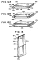
- Heat exchanger tube 141a of the embodiment depicted in Fig. 12A comprises two flat plate portions 143a and 143b (flat plates) provided to face each other with a gap therebetween and defining therebetween a passage 142 for heat exchange medium; and folded portions 144a and 144b formed by plurally bending and folding on both end portions in the widthwise direction of flat plate portion 143a. Folded portions 144a and 144b are joined by brazing to corresponding end portions 145a and 145b in the widthwise direction of the other flat plate portion 143b (joining portions 146a and 146b).
- a first folded piece portion 147a is folded so as to come into contact with the inner surface of flat plate portion 143a at a surface contact condition
- a second folded piece portion 147b is folded so as to come into contact with the prior folded piece portion 147a at a surface contact condition.
- Folded piece portion 147b of folded portions 144a and 144b are joined by brazing, respectively, so as to come into contact with corresponding end portions 145a and 145b of the other flat plate portion 143b at a surface contact condition.
- Such folded portions 144a and 144b are formed by pressing.
- a folded portion 148 is formed on each end portion of the other flat plate portion 143b by folding the end portion once, and folded portion 144a, 144b and corresponding folded portions 148 are joined to each other by brazing so as to come into contact with each other at a surface contact condition.
- folded portion 144a and 144b are formed on corresponding end portions of both flat plate portions 143a and 143b, respectively, by folding each end portion twice, and the corresponding folded portions are joined to each other by brazing so as to come into contact with each other at a surface contact condition.
- the times of folding of a folded portion and the formation of the corresponding end portion of the other flat plate portion 143b may be arbitrarily chosen, and the internal dimension (the height of fluid path) may be determined accurately at a target dimension by determining the number of folded piece portions interposed between both flat plate portions 143a and 143b.
- an internal dimension other than those shown in figures may be determined, and according to target dimensions, the number of folded piece portions interposed between both flat plate portions 143a and 143b and the times of folding of the respective folded portions may be decided.
- Heat exchanger tube 151 of the embodiment depicted in Fig. 13, similarly to that shown in Fig. 12A, comprises two flat plate portions 153a and 153b defining a passage 152 for heat exchange medium; and folded portions 154a and 154b formed by plurally bending and folding on both end portions in the widthwise direction of flat plate portion 153a. Folded portions 154a and 154b are joined by brazing to corresponding end portions 155a and 155b in the widthwise direction of the other flat plate portion 153b (joining portions 156a and 156b).
- the heat exchanger tubes shown in Figs. 10 to 13 are manufactured as products of heat exchangers, generally, by assembling those together with other parts such as fins and header pipes and joining them by brazing in a furnace.
- an inner fin may be inserted into the tube for the purpose of increase of pressure resistance and heat transfer performance.
- usually a clad material with a brazing material is used for any of fins and tube shells for joining by brazing. If a clad material with a brazing material on both surfaces is used, a tube shell may be brazed at a liquid sealing condition, and a bare material with no clad brazing material can be used for fins. Further, when only a tube shell is brazed, any of a method for using a material clad with a brazing material on both surfaces or on only one surface, or a method for using combination of these materials, may be appropriately selected.
- Heat exchanger tubes 121a, 131, 141a and 151 shown in Figs. 10 to 13 are manufactured by the methods shown in Figs. 14 to 17, respectively.
- Heat exchanger tubes 121b, 121c, 141b and 141c may be manufactured by similar methods.
- Fig. 14 shows a method for manufacturing heat exchanger tube 121a depicted in Fig. 10A.
- a flat plate 163 having a predetermined width is formed by cutting a wide flat plate 161 prepared as a material for forming a tube, using an appropriate cutter 162. Then, one end portion in the widthwise direction of flat plate 163 with the predetermined width is bent to fold the end portion twice to form folded portion 125a on the end portion.
- flat plate 163 is bent at a central portion in the widthwise direction in the direction of the upper surface side in Fig. 14 to form bent portion 124, and two flat plate portions 123a and 123b facing each other with a gap therebetween and defining therebetween passage 122 for heat exchange medium are formed.
- folded portion 125a on the end portion of flat plate portion 123a and end portion 125b of flat plate portion 123b are joined to each other (joining portion 126), thereby completing heat exchanger tube 121a depicted in Fig. 10A.
- Fig. 16 shows a method for manufacturing heat exchanger tube 141a depicted in Fig. 12A.
- two flat plates 181a and 181b having different widths are formed by cutting a wide flat plate 161 prepared as a material, using cutter 162.
- folded portions 144a and 144b are formed by bending on both end portions of one flat plate 181a.
- Flat plates 181a and 181b are formed as flat plate portions 143a and 143b.
- Fig. 17 shows a method for manufacturing heat exchanger tube 151 depicted in Fig. 13.
- two flat plates 191a and 191b are formed by cutting a wide flat plate 161 prepared as a material, using cutter 162.
- projecting portion 157 is formed by bending one flat plate 191b at a central portion in the widthwise direction thereof.
- Folded portions 154a and 154b are formed on both end portions of the other flat plate 191a by plurally bending and folding the end portions.
- Folded portions 154a and 154b are joined to corresponding end portions 155a and 155b in the widthwise direction of the other flat plate 191b by brazing (joining portions 156a and 156b), thereby completing heat exchanger tube 151 having therein passage 152 for heat exchange medium depicted in Fig. 13.
- the folded portion formed on the end portion in the widthwise direction of the flat plate portion can be formed by pressing, the conventional roll forming is not necessary, and great reduction of the cost for processing, the cost for manufacturing the tubes, ultimately, the cost for manufacturing the heat exchanger, may be achieved. Because roll forming is not carried out, correction after processing is also unnecessary, thereby greatly reducing generation of defectives, facilitating the manufacture and further reducing the cost for the manufacture.
- the folded portion is formed by plurally bending and folding the end portion in opposite directions, and the internal dimensions of the tube may be determined substantially freely and accurately by the times of folding, and therefore, the freedom of design may be greatly increased.
- the internal dimension of the tube may be determined at a dimension corresponding to a value of (the thickness of the folded piece portion x the number of the folded piece portions) more accurately by bringing the first folded piece portion into contact with the inner surface of the flat plate portion at a condition of surface contact. Therefore, the internal dimensions of the tube may be determined at target dimensions at high accuracy, thereby easily achieving a tube with desired internal dimensions.
- the projecting portion basically is a portion which does not require flux flown from another portion or flux applied from outside, defect of application of flux, as in the structure shown in Fig. 27, does not occur. Therefore, generation of a defective for brazing may be easily prevented.
- the heat exchanger tubes depicted in Figs. 2 to 5 and Figs. 10 to 13 may have the following additional structures. Although the additional structures will be explained as to the heat exchanger tubes depicted in Fig. 2 and Fig. 10A, these structures may similarly be applied to the tubes depicted in Figs. 3 to 5, Figs. 10B and 10C, and Figs. 11 to 13.
- an inner fin 204 formed as a wave type is provided in a passage 203 for heat exchange medium defined between flat plate portions 202a and 202b of tube 201, and the passage 203 is divided into a plurality of paths by inner fin 204.
- the structure of inner fin 204 is not particularly limited, and a structure other than the wave type may be employed. Such an inner fin 204 may be inserted after forming tube 201.
- a plurality of protruded portions 213 protruding toward the inside of the tube are provided on both flat plate portions 212a and 212b of tube 211, and protruded portions 213 are disposed to face each other and the top surfaces thereof are brought into contact with each other.
- Respective protruded portions 213 may be formed easily by embossing a flat plate material before forming the tube, and the tube may be processed after forming the protruded portions 213.
- a plurality of grooves 223a and 223b extending obliquely in the directions to intersect each other are defined on flat plate portions 222a and 222b, respectively.
- these grooves 223a and 223b are defined on a flat plate material 224 before forming tube 221 so that the grooves extend to intersect each other when tube 221 is formed and thereafter, the material may be processed into tube 221.
Landscapes
- Engineering & Computer Science (AREA)
- Physics & Mathematics (AREA)
- Mechanical Engineering (AREA)
- Thermal Sciences (AREA)
- General Engineering & Computer Science (AREA)
- Geometry (AREA)
- Heat-Exchange Devices With Radiators And Conduit Assemblies (AREA)
Applications Claiming Priority (3)
| Application Number | Priority Date | Filing Date | Title |
|---|---|---|---|
| JP95205/97 | 1997-03-28 | ||
| JP9520597A JPH10274489A (ja) | 1997-03-28 | 1997-03-28 | 熱交換器用チューブおよびその製造方法 |
| PCT/JP1998/001370 WO1998044306A1 (fr) | 1997-03-28 | 1998-03-26 | Tube pour echangeur de chaleur et procede de fabrication de ce dernier |
Publications (2)
| Publication Number | Publication Date |
|---|---|
| EP0907062A1 true EP0907062A1 (fr) | 1999-04-07 |
| EP0907062A4 EP0907062A4 (fr) | 1999-11-24 |
Family
ID=14131257
Family Applications (1)
| Application Number | Title | Priority Date | Filing Date |
|---|---|---|---|
| EP98911038A Withdrawn EP0907062A4 (fr) | 1997-03-28 | 1998-03-26 | Tube pour echangeur de chaleur et procede de fabrication de ce dernier |
Country Status (3)
| Country | Link |
|---|---|
| EP (1) | EP0907062A4 (fr) |
| JP (1) | JPH10274489A (fr) |
| WO (1) | WO1998044306A1 (fr) |
Cited By (28)
| Publication number | Priority date | Publication date | Assignee | Title |
|---|---|---|---|---|
| EP1060808A3 (fr) * | 1999-06-18 | 2002-01-02 | Valeo Engine Cooling Aktiebolag | Tuyau ainsi que procédé et dispositif pour sa fabrication |
| EP1065466A3 (fr) * | 1999-07-01 | 2003-09-10 | Ford Motor Company | Turbulateur plat pour un tube et sa méthode de fabrication |
| US6640886B2 (en) | 2001-07-31 | 2003-11-04 | Modine Manufacturing Company | Heat exchanger tube, heat exchanger and method of making the same |
| EP1139052A3 (fr) * | 2000-03-31 | 2005-01-19 | Modine Manufacturing Company | Refroidisseur pour véhicules et procédé de fabrication |
| GB2404241A (en) * | 2003-07-24 | 2005-01-26 | Robin Matthew Hilder | Heat exchanger especially for solar water heating |
| EP1521050A2 (fr) * | 1999-09-08 | 2005-04-06 | Zexel Valeo Climate Control Corporation | Tube d'échangeur de chaleur |
| US6935418B1 (en) | 1999-06-18 | 2005-08-30 | Valeo Engine Cooling Ab | Fluid conveying tube and vehicle cooler provided therewith |
| WO2007027318A1 (fr) * | 2005-08-30 | 2007-03-08 | Caterpillar Inc. | Tube conçu pour un refroidisseur d’air |
| EP1835250A2 (fr) * | 2006-03-14 | 2007-09-19 | Behr GmbH & Co. KG | Procédé de fabrication d'un échangeur de chaleur stratifié et échangeur de chaleur stratifié |
| DE102006035210A1 (de) * | 2006-07-29 | 2008-01-31 | Modine Manufacturing Co., Racine | Flaches Wärmetauscherrohr und Herstellungsverfahren |
| US20090173485A1 (en) * | 2007-11-30 | 2009-07-09 | Ranga Nadig | Fin tube assembly for air cooled heat exchanger and method of manufacturing the same |
| US7921559B2 (en) | 2006-01-19 | 2011-04-12 | Modine Manufacturing Company | Flat tube, flat tube heat exchanger, and method of manufacturing same |
| CN101450355B (zh) * | 2006-01-19 | 2011-10-05 | 摩丁制造公司 | 扁平管道、扁平管道热交换器及其制造方法 |
| US8091621B2 (en) | 2006-01-19 | 2012-01-10 | Modine Manufacturing Company | Flat tube, flat tube heat exchanger, and method of manufacturing same |
| US8191258B2 (en) | 2006-01-19 | 2012-06-05 | Modine Manufacturing Company | Flat tube, flat tube heat exchanger, and method of manufacturing same |
| CN102636064A (zh) * | 2012-04-08 | 2012-08-15 | 泰安鼎鑫冷却器有限公司 | 两侧弯折组合散热管 |
| CN102636062A (zh) * | 2012-04-08 | 2012-08-15 | 泰安鼎鑫冷却器有限公司 | 双片折边组合散热管 |
| CN102636066A (zh) * | 2012-04-08 | 2012-08-15 | 泰安鼎鑫冷却器有限公司 | 单侧弯折组合散热管 |
| US8281489B2 (en) | 2006-01-19 | 2012-10-09 | Modine Manufacturing Company | Flat tube, flat tube heat exchanger, and method of manufacturing same |
| US8434227B2 (en) | 2006-01-19 | 2013-05-07 | Modine Manufacturing Company | Method of forming heat exchanger tubes |
| US8438728B2 (en) | 2006-01-19 | 2013-05-14 | Modine Manufacturing Company | Flat tube, flat tube heat exchanger, and method of manufacturing same |
| US8561451B2 (en) | 2007-02-01 | 2013-10-22 | Modine Manufacturing Company | Tubes and method and apparatus for producing tubes |
| US8683690B2 (en) | 2006-01-19 | 2014-04-01 | Modine Manufacturing Company | Flat tube, flat tube heat exchanger, and method of manufacturing same |
| US8726508B2 (en) | 2006-01-19 | 2014-05-20 | Modine Manufacturing Company | Flat tube, flat tube heat exchanger, and method of manufacturing same |
| US9038267B2 (en) | 2010-06-10 | 2015-05-26 | Modine Manufacturing Company | Method of separating heat exchanger tubes and an apparatus for same |
| DE102014108463A1 (de) * | 2014-06-16 | 2015-12-17 | Fischer Edelstahlrohre Gmbh | Wärmeübertragerrohr und Verfahren zur Herstellung eines Wärmeübertragerrohrs |
| CN106931818A (zh) * | 2015-12-29 | 2017-07-07 | 泰安鼎鑫冷却器有限公司 | 一种多处局部加强型散热管 |
| EP3665428A4 (fr) * | 2017-08-07 | 2021-05-05 | Modine Manufacturing Company | Tube d'échangeur de chaleur |
Families Citing this family (11)
| Publication number | Priority date | Publication date | Assignee | Title |
|---|---|---|---|---|
| WO2000052409A1 (fr) * | 1999-02-26 | 2000-09-08 | Bosch Automotive Systems Corporation | Echangeur de chaleur et procede de fabrication d'un tube pour cet echangeur de chaleur |
| JP4614266B2 (ja) * | 2004-07-23 | 2011-01-19 | 臼井国際産業株式会社 | 流体攪拌用フィン並びに該フィンを内装した伝熱管および熱交換器または熱交換型ガス冷却装置 |
| DE102006016711B4 (de) * | 2006-04-08 | 2016-11-03 | Modine Manufacturing Co. | Flachrohr für Wärmetauscher |
| CN102636065A (zh) * | 2012-04-08 | 2012-08-15 | 泰安鼎鑫冷却器有限公司 | 两侧折叠式组合散热管 |
| CN102636063A (zh) * | 2012-04-08 | 2012-08-15 | 泰安鼎鑫冷却器有限公司 | 单折边对接组合散热管 |
| CN105021077A (zh) * | 2014-05-02 | 2015-11-04 | 泰安鼎鑫冷却器有限公司 | 一种双向连续折叠高强度散热管 |
| CN106556281B (zh) * | 2015-09-29 | 2018-07-06 | 泰安鼎鑫冷却器有限公司 | 一种组合式散热芯体 |
| CN106556279A (zh) * | 2015-09-29 | 2017-04-05 | 泰安鼎鑫冷却器有限公司 | 一种多部件组合式散热芯体 |
| CN106767093B (zh) * | 2016-12-27 | 2023-12-05 | 无锡逸龙铝热科技有限公司 | 一种直接成型压片式散热器扁管 |
| CN106643252A (zh) * | 2017-01-09 | 2017-05-10 | 南宁市安和机械设备有限公司 | 加强型b型散热管 |
| EP3399266B1 (fr) * | 2017-05-02 | 2023-05-31 | Valeo Systemes Thermiques | Tube plat pour échangeur de chaleur et échangeur de chaleur |
Citations (5)
| Publication number | Priority date | Publication date | Assignee | Title |
|---|---|---|---|---|
| US2009863A (en) * | 1934-11-22 | 1935-07-30 | Reuben N Trane | Heat exchanger |
| GB683161A (en) * | 1950-07-22 | 1952-11-26 | Morris Motors Ltd | Improvements relating to heat-exchangers |
| EP0283937A1 (fr) * | 1987-03-25 | 1988-09-28 | Nihon Radiator Co., Ltd. | Tube plat pour échangeur de chaleur à ailette insérée |
| GB2223091A (en) * | 1988-08-12 | 1990-03-28 | Calsonic Corp | Heat exchange tubes |
| EP0457470A1 (fr) * | 1990-05-11 | 1991-11-21 | Showa Aluminum Kabushiki Kaisha | Tube pour échangeurs de chaleur et méthode de fabrication du tube |
Family Cites Families (5)
| Publication number | Priority date | Publication date | Assignee | Title |
|---|---|---|---|---|
| JPS59125395A (ja) * | 1982-12-29 | 1984-07-19 | Showa Alum Corp | 熱交換器用管の製造法 |
| JPS6166091A (ja) * | 1984-09-06 | 1986-04-04 | Toyo Radiator Kk | 熱交換器用チユ−ブ材及び該チユ−ブ材による熱交換器コアの製造方法 |
| JPH0486489A (ja) * | 1990-07-27 | 1992-03-19 | Showa Alum Corp | 熱交換器用チューブ |
| JPH0777397A (ja) * | 1993-09-07 | 1995-03-20 | Kawaju Reinetsu Kogyo Kk | 伝熱管 |
| JPH08226784A (ja) * | 1995-02-21 | 1996-09-03 | Sanden Corp | 熱交換器及びその製造方法 |
-
1997
- 1997-03-28 JP JP9520597A patent/JPH10274489A/ja active Pending
-
1998
- 1998-03-26 WO PCT/JP1998/001370 patent/WO1998044306A1/fr not_active Application Discontinuation
- 1998-03-26 EP EP98911038A patent/EP0907062A4/fr not_active Withdrawn
Patent Citations (5)
| Publication number | Priority date | Publication date | Assignee | Title |
|---|---|---|---|---|
| US2009863A (en) * | 1934-11-22 | 1935-07-30 | Reuben N Trane | Heat exchanger |
| GB683161A (en) * | 1950-07-22 | 1952-11-26 | Morris Motors Ltd | Improvements relating to heat-exchangers |
| EP0283937A1 (fr) * | 1987-03-25 | 1988-09-28 | Nihon Radiator Co., Ltd. | Tube plat pour échangeur de chaleur à ailette insérée |
| GB2223091A (en) * | 1988-08-12 | 1990-03-28 | Calsonic Corp | Heat exchange tubes |
| EP0457470A1 (fr) * | 1990-05-11 | 1991-11-21 | Showa Aluminum Kabushiki Kaisha | Tube pour échangeurs de chaleur et méthode de fabrication du tube |
Non-Patent Citations (1)
| Title |
|---|
| See also references of WO9844306A1 * |
Cited By (34)
| Publication number | Priority date | Publication date | Assignee | Title |
|---|---|---|---|---|
| EP1060808A3 (fr) * | 1999-06-18 | 2002-01-02 | Valeo Engine Cooling Aktiebolag | Tuyau ainsi que procédé et dispositif pour sa fabrication |
| US6510870B1 (en) | 1999-06-18 | 2003-01-28 | Valeo Engine Cooling Ab | Fluid conveying tube as well as method and device for manufacturing the same |
| US6935418B1 (en) | 1999-06-18 | 2005-08-30 | Valeo Engine Cooling Ab | Fluid conveying tube and vehicle cooler provided therewith |
| US6957487B1 (en) | 1999-06-18 | 2005-10-25 | Valeo Engine Cooling, Ab | Fluid conveying tube as well as method and device for manufacturing the same |
| EP1065466A3 (fr) * | 1999-07-01 | 2003-09-10 | Ford Motor Company | Turbulateur plat pour un tube et sa méthode de fabrication |
| EP1521050A2 (fr) * | 1999-09-08 | 2005-04-06 | Zexel Valeo Climate Control Corporation | Tube d'échangeur de chaleur |
| EP1521050A3 (fr) * | 1999-09-08 | 2005-10-19 | Zexel Valeo Climate Control Corporation | Tube d'échangeur de chaleur |
| EP1139052A3 (fr) * | 2000-03-31 | 2005-01-19 | Modine Manufacturing Company | Refroidisseur pour véhicules et procédé de fabrication |
| US6640886B2 (en) | 2001-07-31 | 2003-11-04 | Modine Manufacturing Company | Heat exchanger tube, heat exchanger and method of making the same |
| GB2404241A (en) * | 2003-07-24 | 2005-01-26 | Robin Matthew Hilder | Heat exchanger especially for solar water heating |
| WO2007027318A1 (fr) * | 2005-08-30 | 2007-03-08 | Caterpillar Inc. | Tube conçu pour un refroidisseur d’air |
| US8091621B2 (en) | 2006-01-19 | 2012-01-10 | Modine Manufacturing Company | Flat tube, flat tube heat exchanger, and method of manufacturing same |
| US8281489B2 (en) | 2006-01-19 | 2012-10-09 | Modine Manufacturing Company | Flat tube, flat tube heat exchanger, and method of manufacturing same |
| US8726508B2 (en) | 2006-01-19 | 2014-05-20 | Modine Manufacturing Company | Flat tube, flat tube heat exchanger, and method of manufacturing same |
| US7921559B2 (en) | 2006-01-19 | 2011-04-12 | Modine Manufacturing Company | Flat tube, flat tube heat exchanger, and method of manufacturing same |
| CN101450355B (zh) * | 2006-01-19 | 2011-10-05 | 摩丁制造公司 | 扁平管道、扁平管道热交换器及其制造方法 |
| US8683690B2 (en) | 2006-01-19 | 2014-04-01 | Modine Manufacturing Company | Flat tube, flat tube heat exchanger, and method of manufacturing same |
| US8191258B2 (en) | 2006-01-19 | 2012-06-05 | Modine Manufacturing Company | Flat tube, flat tube heat exchanger, and method of manufacturing same |
| US8438728B2 (en) | 2006-01-19 | 2013-05-14 | Modine Manufacturing Company | Flat tube, flat tube heat exchanger, and method of manufacturing same |
| US8434227B2 (en) | 2006-01-19 | 2013-05-07 | Modine Manufacturing Company | Method of forming heat exchanger tubes |
| EP1835250A3 (fr) * | 2006-03-14 | 2012-08-01 | Behr GmbH & Co. KG | Procédé de fabrication d'un échangeur de chaleur stratifié et échangeur de chaleur stratifié |
| EP1835250A2 (fr) * | 2006-03-14 | 2007-09-19 | Behr GmbH & Co. KG | Procédé de fabrication d'un échangeur de chaleur stratifié et échangeur de chaleur stratifié |
| DE102006035210B4 (de) * | 2006-07-29 | 2016-10-06 | Modine Manufacturing Co. | Flaches Wärmetauscherrohr und Herstellungsverfahren |
| DE102006035210A1 (de) * | 2006-07-29 | 2008-01-31 | Modine Manufacturing Co., Racine | Flaches Wärmetauscherrohr und Herstellungsverfahren |
| US8561451B2 (en) | 2007-02-01 | 2013-10-22 | Modine Manufacturing Company | Tubes and method and apparatus for producing tubes |
| US20090173485A1 (en) * | 2007-11-30 | 2009-07-09 | Ranga Nadig | Fin tube assembly for air cooled heat exchanger and method of manufacturing the same |
| US9038267B2 (en) | 2010-06-10 | 2015-05-26 | Modine Manufacturing Company | Method of separating heat exchanger tubes and an apparatus for same |
| CN102636064A (zh) * | 2012-04-08 | 2012-08-15 | 泰安鼎鑫冷却器有限公司 | 两侧弯折组合散热管 |
| CN102636062A (zh) * | 2012-04-08 | 2012-08-15 | 泰安鼎鑫冷却器有限公司 | 双片折边组合散热管 |
| CN102636066A (zh) * | 2012-04-08 | 2012-08-15 | 泰安鼎鑫冷却器有限公司 | 单侧弯折组合散热管 |
| DE102014108463A1 (de) * | 2014-06-16 | 2015-12-17 | Fischer Edelstahlrohre Gmbh | Wärmeübertragerrohr und Verfahren zur Herstellung eines Wärmeübertragerrohrs |
| DE102014108463B4 (de) * | 2014-06-16 | 2020-03-05 | Fischer Edelstahlrohre Gmbh | Wärmeübertragerrohr, Wärmeübertrager und Verfahren zur Herstellung eines Wärmeübertragerrohrs |
| CN106931818A (zh) * | 2015-12-29 | 2017-07-07 | 泰安鼎鑫冷却器有限公司 | 一种多处局部加强型散热管 |
| EP3665428A4 (fr) * | 2017-08-07 | 2021-05-05 | Modine Manufacturing Company | Tube d'échangeur de chaleur |
Also Published As
| Publication number | Publication date |
|---|---|
| JPH10274489A (ja) | 1998-10-13 |
| EP0907062A4 (fr) | 1999-11-24 |
| WO1998044306A1 (fr) | 1998-10-08 |
Similar Documents
| Publication | Publication Date | Title |
|---|---|---|
| EP0907062A1 (fr) | Tube pour echangeur de chaleur et procede de fabrication de ce dernier | |
| JP4171760B2 (ja) | 偏平管および偏平管の製造方法 | |
| US7749609B2 (en) | Metal plate for producing flat tube, flat tube and process for producing the flat tube | |
| EP1158260B1 (fr) | Echangeur de chaleur, procede de fabrication d'echangeur de chaleur, et procede de fabrication de tube pour echangeur de chaleur | |
| EP0617250A2 (fr) | Tubes de refroidissement pour échangeurs de chaleur | |
| AU2002304254A1 (en) | Metal plate for producing flat tube, flat tube and process for producing the flat tube | |
| JP2001041675A (ja) | 熱交換器用チューブおよび熱交換器 | |
| JPH05172488A (ja) | 熱交換器用ヘッダ−パイプの仕切板組付構造及び組付方法 | |
| JPH0825028A (ja) | 積層型熱交換器の偏平チューブのろう付け方法 | |
| EP1213555A1 (fr) | Echangeur de chaleur, tube pour echangeur de chaleur, procede de fabrication de l'echangeur de chaleur et du tube | |
| US20080245513A1 (en) | Tube for heat exchanger and method of manufacturing tube | |
| GB2286882A (en) | Bent finned tube heat exchanger. | |
| JPH02154992A (ja) | 扁平管使用熱交換器 | |
| GB2371505A (en) | Heat exchanger construction | |
| JP2007113895A (ja) | 熱交換器および熱交換器の製造方法 | |
| JP4626472B2 (ja) | 熱交換器および熱交換器の製造方法 | |
| JP2007107755A (ja) | 熱交換器、熱交換器用チューブ、およびそれらの製造方法 | |
| JP3912889B2 (ja) | 熱交換器用チューブおよびその製造方法 | |
| EP0866301A1 (fr) | Echangeur de chaleur et son procede de fabrication | |
| JP2701939B2 (ja) | アルミニウム製熱交換器の製造方法 | |
| JPH05277714A (ja) | 熱交換器の製造方法 | |
| JP2009264664A (ja) | 熱交換器 | |
| JP5154837B2 (ja) | 熱交換器 | |
| JPH10206079A (ja) | 熱交換器 | |
| JP2002250596A (ja) | 積層型熱交換器の製造方法 |
Legal Events
| Date | Code | Title | Description |
|---|---|---|---|
| PUAI | Public reference made under article 153(3) epc to a published international application that has entered the european phase |
Free format text: ORIGINAL CODE: 0009012 |
|
| AK | Designated contracting states |
Kind code of ref document: A1 Designated state(s): DE FR GB IT SE |
|
| 17P | Request for examination filed |
Effective date: 19990210 |
|
| A4 | Supplementary search report drawn up and despatched |
Effective date: 19991012 |
|
| AK | Designated contracting states |
Kind code of ref document: A4 Designated state(s): DE FR GB IT SE |
|
| 17Q | First examination report despatched |
Effective date: 20011203 |
|
| STAA | Information on the status of an ep patent application or granted ep patent |
Free format text: STATUS: THE APPLICATION IS DEEMED TO BE WITHDRAWN |
|
| 18D | Application deemed to be withdrawn |
Effective date: 20020416 |