Technical Field of the Invention
The present invention relates to a heat exchanger tube and
a method for manufacturing the same, and specifically to a heat
exchanger tube suitable in use for heat exchangers for vehicles
and a method for manufacturing it, and further, to a heat
exchanger having the heat exchanger tube.
Background Art of the Invention
A heat exchanger tube, in more detail, a heat exchanger
tube for flowing heat exchange medium in a heat exchanger, has
been manufactured, for example, by bending a single flat plate
material in the widthwise direction by roll bending, and
joining tip portions of the end portions of the bent material to
each other. In such a manufacturing method, for example, as
shown in Fig. 27, a heat exchanger tube 301 is formed by
abutting and joining the tip portions to each other at a
junction 302. The tip portions are joined, for example, by
electric-resistance welding.
In such a method as shown in Fig. 27, however, when an
electro-unite tube formed by roll forming a single plate is used,
because tip portions of the bent plate are welded at junction
302, the contact area is small and the strength for joining is
low, and therefore, pressure resistance may be low. Further,
because a long-sized material must be roll formed, the
processing cost of tube 301 may increase. Moreover, because, in
most cases, cutting to a predetermined length is carried out
after processing in the roll forming of long-sized material,
defective tubes may be produced, or correction after the
manufacture may be required, and therefore, the cost for the
manufacture may increase from this point of view. Furthermore,
because only the tip portions of the bent plate are joined at
junction 302, the internal dimensions of formed tube 301, in
particular, the height of the fluid path, may be difficult to be
accurately determined to a target dimension, and the dimension
may be dispersed. Still further, if the target height of the
fluid path is changed, it may be difficult to accurately follow
the change.
Further, in a method for manufacturing a tube shown in Fig.
28, there are the following problems. In a heat exchanger
having a core portion with tubes and fins disposed alternately,
usually a method for heating and brazing the core portion at a
condition of temporary assembly in a furnace is employed.
However, as shown in Fig. 28, in the structure in that a joining
portion 312 for forming a heat exchanger tube 311 is provided
at a central portion in the widthwise direction of the tube,
flux may not be applied sufficiently to the brazing portion,
defect of brazing may occur, and a defective for sealing the
heat exchange medium may be generated.
Moreover, in the structure in that joining portion 312
extending along tube 311 at a central portion in the widthwise
direction of the tube is provided, as shown in Fig. 28, a high
strength of tube 311 may be ensured. However, in the structure
in that any projecting or abutting portion is not provided at a
central portion in the widthwise direction of tube 301, as shown
in Fig. 27, when the core portion is brazed, binding force may
be applied to the core portion originating from the difference
between the thermal expansion of the core portion and that of a
jig for brazing (a jig for temporarily fixing the assembly of
the core portion), and therefore, the tube may be deformed, or
a defective of brazing (a defective for sealing) may be
generated.
Disclosure of the Invention
Accordingly, an object of the present invention is to
provide a heat exchanger tube and a method for manufacturing it,
having such features that the junction strength of a joined
portion of the heat exchanger tube is high enough to ensure
sufficiently high pressure resistance, that the internal
dimensions of the tube may be changed easily and accurately,
that flux may be sufficiently applied to portions required for
brazing, and that a reinforced structure may be easily employed
at the central portion in the widthwise direction of the tube.
To achieve the foregoing object, a heat exchanger tube
according to the present invention comprises two flat plate
portions provided to face each other and defining therebetween a
passage for heat exchange medium; and a folded portion provided
on at least one end portion in the widthwise direction of at
least one of the flat plate portions. The folded portion is
formed by folding the end portion so as to have a thickness
which is an integral multiple of a thickness of a plate forming
the end portion, and the folded portion and a corresponding end
portion in the widthwise direction of the other flat plate
portion are joined to each other.
In the heat exchanger tube, a bent portion, which
integrally connects two flat plate portions, may be formed at
one end portion in the widthwise direction of the heat
exchanger tube, the folded portion may be formed on each flat
plate portion at the other end portion in the widthwise
direction of the heat exchanger tube, and the respective folded
portions may be joined to each other. Alternatively, the folded
portion may be formed on each end portion in the widthwise
direction of each flat plate portion, and each set of
corresponding folded portions on the respective end portions may
be joined to each other.
The folded portion may be formed by once folding at least
one end portion in the widthwise direction of at least one flat
plate portion, and the folded portion may be formed by plurally
folding at least one end portion in the widthwise direction of
at least one of the flat plate portions. In the case of the
folded portion formed by plurally folding, the folded portion
is formed, so that a first folded piece portion comes into
contact with an inner surface of a flat plate portion at a
condition of surface contact, and a following folded piece
portion comes into contact with a surface of a prior folded
piece portion at a condition of surface contact. Such folded
portions may be formed, for example, by pressing.
Further, the tube may be structured such that a projecting
portion is formed at a central portion in the widthwise
direction of one flat plate portion by bending the flat plate
portion itself, and the projecting portion extends toward the
other flat plate portion so as to substantially come into
contact with the other flat plate portion. The above-described
folded portion may be brazed to the corresponding end portion in
the widthwise direction of the other flat plate portion.
To such a heat exchanger tube, the following structures may
be added. For example, an inner fin may be provided between
the flat plate portions. Further, a plurality of protruded
portions protruding toward the inside of the tube may be
provided on at least one of the flat plate portions, and
protruded portions facing to each other, or, a protruded portion
and an inner surface of a flat plate portion facing the
protruded portion, may be abutted to each other. Further, the
flat plate portions may be formed to expand toward outside of
the tube so that a central portion in the widthwise direction of
each flat portion is formed as a peak, thereby increasing the
pressure resistance of the tube. Furthermore, grooves may be
defined on an inner surface of each flat plate portion so that
the grooves on one flat plate portion extend to intersect the
grooves on the other flat plate portion.
A heat exchanger according to the present invention has
such a heat exchanger tube. The type of the heat exchanger is
not particularly restricted. For example, the present invention
is applied to a heat exchanger wherein tubes and fins are
alternately disposed.
A method for manufacturing a heat exchanger tube according
to the present invention comprises the steps of (a) folding at
least one end portion in the widthwise direction of a flat
plate with a predetermined width to form a folded portion having
a thickness which is an integral multiple of a thickness of the
flat plate forming the end portion, (b) bending the flat plate
at a central portion in the widthwise direction of the flat
plate so that the folded portion is positioned inside, to form
two flat plate portions defining therebetween a passage for
heat exchange medium, and (c) joining the folded portion formed
on at least one end portion of at least one of the flat plate
portions to a corresponding end portion of the other flat plate
portion.
Another method for manufacturing a heat exchanger tube
according to the present invention comprises the steps of (a)
folding both end portions in the widthwise direction of at least
one flat plate of two flat plates having respective
predetermined widths to form a folded portion at each end
portion, the folded portion having a thickness which is an
integral multiple of a thickness of the flat plate forming the
end portion, and (b) joining the folded portions formed on both
end portions of the flat plate and corresponding end portions
of the other flat plate to each other.
Also in such manufacturing methods, the folded portion may
be formed by once folding the end portion in the widthwise
direction of the flat plate, and the folded portion may be
formed by plurally folding. In the case of the folded portion
formed by plurally folding, the folded portion is formed, so
that a first folded piece portion comes into contact with an
inner surface of a flat plate at a condition of surface contact,
and a following folded piece portion comes into contact with a
surface of a prior folded piece portion at a condition of
surface contact. Such folded portions may be formed, for
example, by pressing.
Further, before or after the folded portion is formed, a
projecting portion may be formed at a central portion in the
widthwise direction of one of flat plate portions forming the
tube by bending the flat plate portion itself, so that the
projecting portion is formed to extend toward the other flat
plate portion so as to substantially come into contact with the
other flat plate portion. The folded portion may be brazed to
the corresponding end portion of a flat plate portion facing the
folded portion.
The method for manufacturing a heat exchanger may have a
step of providing an inner fin between two flat plate portions
forming the tube. Further, a plurality of protruded portions
protruding toward the inside of the tube may be formed on the
flat plate when the tube is formed. Furthermore, grooves may
be defined on surfaces of flat plate portions forming the tube
so that the grooves on one flat plate portion extend to
intersect the grooves on the other flat plate portion when the
tube is formed.
In the heat exchanger tube and the method for manufacturing
the same, the folded portion formed on the end portion in the
widthwise direction of at least one flat plate portion can be
formed, for example, by pressing. Therefore, the cost for the
processing is cheap, and because a material having been cut at a
predetermined width is pressed, defect of the processing does
not occur and correction after the processing is not necessary.
As a result, the cost for the manufacture may be greatly
reduced.
Further, because tip portions are not joined to each other
as in the conventional tubes but the folded portion can be
joined to the end portion in the widthwise direction of the
other flat plate portion at a condition of surface contact
(this end portion may be formed as a folded portion), the
junction area becomes sufficiently wide, a high junction
strength may be ensured, and a high pressure resistance may be
realized. Because the folded portion is formed by folding the
plate once or a plurality of times so that the folded portion
has a thickness of an integral multiple of the thickness of the
plate forming the end portion in the widthwise direction of the
plate, and so that the folded piece portion is stacked at a
condition of surface contact, a high strength of the folded
portion itself may be ensured, as well as a high junction
strength may be ensured by joined surfaces at a condition of
surface contact, and a high pressure resistance may be achieved
as the whole of the tube.
The thickness of the folded portion corresponds to a height
of a fluid path formed in the tube. The thickness of the
folded portion can be determined by the times of folding in the
folded portion. Namely, the thickness of the folded portion,
in particular, the thickness of the folded portion contributing
decision of the internal dimensions of the tube, can be
determined by the times of folding, that is, by the number of
stacked folded piece portions, thereby greatly increasing the
freedom of design. When plurally folded, or when folded piece
portions are joined to each other, the thickness may be
accurately determined as a dimension corresponding to a value of
(the thickness of the folded piece portion x the number of the
folded piece portions) by the surface contact between the folded
piece portions or between the first folded piece portion and
the inner surface of the flat plate portion having the first
folded piece portion. Therefore, the internal dimensions of
the tube to be formed may be accurately determined at target
dimensions, thereby obtaining a tube with high accuracy.
When a projecting portion is provided, because the
projecting portion can be formed by bending the flat plate
portion itself, a portion requiring brazing is not generated at
a central portion in the widthwise direction of the tube.
Therefore, lack of flux, defect of brazing due to the lack of
flux, and defect of sealing may not occur.
Further, when such a projecting portion is provided, while
the above-described advantages are maintained, the tube may be
reinforced at the central portion in the widthwise direction.
Therefore, when the core portion is brazed, the deformation of
the tube, defect of brazing originating from the difference
between the thermal expansion of the core portion and that of a
jig for brazing, and generation of a defective for sealing may
be prevented.
Brief explanation of the drawing
Fig. 1 is an elevational view of a heat exchanger according
to an embodiment of the present invention.
Fig. 2 is a partial perspective view of a heat exchanger
tube according to an embodiment of the present invention.
Fig. 3 is a partial perspective view of a heat exchanger
tube according to another embodiment of the present invention.
Fig. 4 is a partial perspective view of a heat exchanger
tube according to a further embodiment of the present invention.
Fig. 5 is a partial perspective view of a heat exchanger
tube according to a still further embodiment of the present
invention.
Fig. 6 is a process flow diagram showing a method for
manufacturing the heat exchanger tube depicted in Fig. 2.
Fig. 7 is a process flow diagram showing a method for
manufacturing the heat exchanger tube depicted in Fig. 3.
Fig. 8 is a process flow diagram showing a method for
manufacturing the heat exchanger tube depicted in Fig. 4.
Fig. 9 is a process flow diagram showing a method for
manufacturing the heat exchanger tube depicted in Fig. 5.
Fig. 10 shows partial perspective views of heat exchanger
tubes according to still further embodiments of the present
invention.
Fig. 11 is a partial perspective view of a heat exchanger
tube according to a still further embodiment of the present
invention.
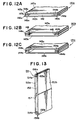
Fig. 12 shows partial perspective views of heat exchanger
tubes according to still further embodiments of the present
invention.
Fig. 13 is a partial perspective view of a heat exchanger
tube according to a still further embodiment of the present
invention.
Fig. 14 is a process flow diagram showing a method for
manufacturing the heat exchanger tube depicted in Fig. 10A.
Fig. 15 is a process flow diagram showing a method for
manufacturing the heat exchanger tube depicted in Fig. 11.
Fig. 16 is a process flow diagram showing a method for
manufacturing the heat exchanger tube depicted in Fig. 12A.
Fig. 17 is a process flow diagram showing a method for
manufacturing the heat exchanger tube depicted in Fig. 13.
Fig. 18 is a partial perspective view of a heat exchanger
tube according to a modification of the embodiment depicted in
Fig. 2.
Fig. 19 is a partial perspective view of a heat exchanger
tube according to a modification of the embodiment depicted in
Fig. 10A.
Fig. 20A is a partial perspective view of a heat exchanger
tube according to another modification of the embodiment
depicted in Fig. 2, and Fig. 20B is a sectional view of the
tube as viewed along the line XXB-XXB of Fig. 20A.
Fig. 21A is a partial perspective view of a heat exchanger
tube according to another modification of the embodiment
depicted in Fig. 10A, and Fig. 21B is a sectional view of the
tube as viewed along the line XXIB-XXIB of Fig. 21A.
Fig. 22A is a partial perspective view of a heat exchanger
tube according to a further modification of the embodiment
depicted in Fig. 2, and Fig. 22B is an enlarged elevational
view of the tube depicted in Fig. 22A.
Fig. 23A is a partial perspective view of a heat exchanger
tube according to a further modification of the embodiment
depicted in Fig. 10A, and Fig. 23B is an enlarged elevational
view of the tube depicted in Fig. 23A.
Fig. 24 is a partial plan view of a plate material before
processed to the tube depicted in Fig. 22A or 23A.
Fig. 25 is a sectional view of a heat exchanger tube
according to a still further modification of the embodiment
depicted in Fig. 2.
Fig. 26 is a sectional view of a heat exchanger tube
according to a still further modification of the embodiment
depicted in Fig. 10A.
Fig. 27 is a partial perspective view of a conventional
heat exchanger tube.
Fig. 28 is a partial perspective view of another
conventional heat exchanger tube.
The Best mode for carrying out the Invention
Hereinafter, preferred embodiments of the present invention
will be explained with reference to the drawings.
Fig. 1 depicts a heat exchanger 1 according to an
embodiment of the present invention. Heat exchanger 1 has two
tanks 2 and 3 provided at entrance and exit sides, a plurality
of heat exchanger tubes 4 provided between tanks 2 and 3 for
communicating between tanks 2 and 3 and each forming therein a
passage for heat exchange medium, and corrugated fins 5. Heat
exchanger tubes 4 and fins 5 are disposed alternately. In this
embodiment, side plates 7 and 8 are provided on the outermost
portions of a core portion 6 having heat exchanger tubes 4 and
fins 5. Brackets 9 and 10 are attached to the outer surface of
side plate 8 and the side surface of tank 2 for mounting heat
exchanger 1. Fittings 11 and 12 for connecting pipes or other
equipments are provided on tanks 2 and 3, respectively.
Such a heat exchanger tube 4 of heat exchanger 1 is
constituted, for example, as shown in Figs. 2 to 5 or Figs. 10
to 13 ( heat exchanger tubes 21, 31, 41, 51, 121a, 121b, 121c,
131, 141a, 141b, 141c and 151).
Heat exchanger tube 21 of the embodiment depicted in Fig. 2
comprises two flat plate portions 23a and 23b provided to face
each other with a gap therebetween and defining therebetween a
passage 22 for heat exchange medium; a bent portion 24 formed
at one end portion in the widthwise direction of heat exchanger
tube 21, which integrally connects two flat plate portions 23a
and 23b; and folded portions 25a and 25b formed on the other end
portions in the widthwise direction of respective flat plate
portions 23a and 23b. Folded portions 25a and 25b are formed by
bending by folding the respective end portions of flat plate
portions 23a and 23b. Respective folded portions 25a and 25b
are formed so that the inner surfaces of respective folded
portions 25a and 25b come into contact with the surfaces of
respective flat plate portions 23a and 23b positioned inside of
the tube at a condition of surface contact, and so that the
outer surfaces of folded portions 25a and 25b facing each other
extend in parallel to each other. Folded portions 25a and 25b
are formed by pressing. Folded portions 25a and 25b are joined
to each other by brazing at a position of the parallel outer
surfaces formed by folding (surfaces facing each other)
(joining portion 26).
Heat exchanger tube 31 of the embodiment depicted in Fig. 3,
similarly to that of the above-described heat exchanger tube 21,
comprises two flat plate portions 33a and 33b defining a
passage 32 for heat exchange medium; a bent portion 34
integrally connecting two flat plate portions 33a and 33b; and
folded portions 35a and 35b formed on one end portion in the
widthwise direction of each of flat plate portions 33a and 33b.
Folded portions 35a and 35b are joined to each other by
brazing at the outer surfaces formed by folding (joining portion
36). In this embodiment, a projecting portion 37 is formed at
a central portion in the widthwise direction of one flat plate
portion 33b by bending flat plate portion 33b itself so that
projecting portion 37 extends toward the other flat plate
portion 33a so as to substantially come into contact with the
inner surface of flat plate portion 33a. The top surface of
this projecting portion 37 may be joined to the inner surface
of flat plate portion 33a, or may be merely brought into
contact with the inner surface.
Heat exchanger tube 41 of the embodiment depicted in Fig. 4
comprises two flat plate portions 43a and 43b provided to face
each other with a gap therebetween and defining therebetween a
passage 42 for heat exchange medium; and folded portions 44a,
44b and 45a, 45b formed by bending and folding on both end
portions in the widthwise direction of respective flat plate
portions 43a and 43b. Corresponding folded portions 44a and
45a and folded portions 44b and 45b are joined to each other by
brazing at a position of the outer surfaces formed by folding
(joining portions 46a and 46b).
Heat exchanger tube 51 of the embodiment depicted in Fig. 5,
similarly to that depicted in Fig. 4, comprises two flat plate
portions 53a and 53b defining a passage 52 for heat exchange
medium; and folded portions 54a, 54b and 55a, 55b formed on
both end portions in the widthwise direction of respective flat
plate portions 53a and 53b. Corresponding folded portions 54a
and 55a and folded portions 54b and 55b are joined to each other
by brazing at a position of the outer surfaces formed by
folding (joining portions 56a and 56b). In this embodiment, a
projecting portion 57 is formed at a central portion in the
widthwise direction of one flat plate portion 53b by bending
flat plate portion 53b itself so that projecting portion 57
extends toward the other flat plate portion 53a so as to
substantially come into contact with the inner surface of flat
plate portion 53a. The top surface of this projecting portion
57 may be joined to the inner surface of flat plate portion 53a,
or may be merely brought into contact with the inner surface.
Heat exchanger tubes 21, 31, 41 and 51 shown in Figs. 2 to
5 are manufactured by the methods shown in Figs. 6 to 9,
respectively.
Fig. 6 shows a method for manufacturing heat exchanger tube
21 depicted in Fig. 2. First, a flat plate 63 having a
predetermined width is formed by cutting a wide flat plate 61
prepared as a material for forming a tube, using an appropriate
cutter 62. Then, both end portions in the widthwise direction
of flat plate 63 with the predetermined width are bent to fold
the end portions (in a direction of the upper surface side in
Fig. 6), to form folded portions 25a and 25b on the respective
end portions.
Next, flat plate 63 is bent at a central portion in the
above-described direction (direction of the upper surface side
in Fig. 6), and two flat plate portions 23a and 23b facing each
other with a gap therebetween and defining therebetween passage
22 for heat exchange medium are formed. Then, folded portions
25a and 25b are joined to each other at a position of the outer
surfaces formed by folding (joining portion 26), thereby
completing heat exchanger tube 21 depicted in Fig. 2.
Fig. 7 shows a method for manufacturing heat exchanger tube
31 depicted in Fig. 3. First, a flat plate 71 having a
predetermined width slightly larger than that shown in Fig. 6
is formed by cutting a wide flat plate 61 prepared as a
material, using cutter 62. Then, projecting portion 37 is
formed by bending flat plate 71 at a predetermined position
thereof. Thereafter, both end portions in the widthwise
direction of flat plate 71 are bent to fold the end portions in
the same direction as that formed with projecting portion 37 to
form folded portions 35a and 35b on the respective end portions.
Next, flat plate 71 is bent at a central portion in the same
surface-side direction to form bent portion 34, and two flat
plate portions 33a and 33b facing each other with a gap
therebetween and defining therebetween passage 32 for heat
exchange medium are formed. Then, folded portions 35a and 35b
are joined to each other at a position of the outer surfaces
formed by folding (joining portion 36), thereby completing heat
exchanger tube 31 depicted in Fig. 3.
Fig. 8 shows a method for manufacturing heat exchanger tube
41 depicted in Fig. 4. First, two flat plates 81a and 81b
having an identical width are formed by cutting a wide flat
plate 61 prepared as a material, using cutter 62. Then, folded
portions 44a, 44b and 45a, 45b are formed by bending on both end
portions of respective flat plates 81a and 81b. Flat plates
81a and 81b are formed as flat plate portions 43a and 43b. Flat
plates 81a and 81b are positioned so that corresponding folded
portions 44a and 45a and folded portions 44b and 45b face each
other, and the corresponding folded portions 44a and 45a and
folded portions 44b and 45b are joined to each other at
positions of the outer surfaces formed by folding (joining
portions 46a and 46b), thereby completing heat exchanger tube
41 having therein passage 42 for heat exchange medium depicted
in Fig. 4.
Fig. 9 shows a method for manufacturing heat exchanger tube
51 depicted in Fig. 5. First, two flat plates 91a and 91b
having different widths are formed by cutting a wide flat plate
61 prepared as a material, using cutter 62. Then, projecting
portion 57 is formed by bending wider flat plate 91b at a
central portion in the widthwise direction thereof. Folded
portions 54a, 54b and 55a, 55b are formed by bending on both end
portions of respective flat plates 91a and 91b. Flat plates
91a and 91b are formed as flat plate portions 53a and 53b. Flat
plates 91a and 91b are positioned so that corresponding folded
portions 54a and 55a and folded portions 54b and 55b face each
other, and the corresponding folded portions 54a and 55a and
folded portions 54b and 55b are joined to each other at
positions of the outer surfaces formed by folding (joining
portions 56a and 56b), thereby completing heat exchanger tube
51 having therein passage 52 for heat exchange medium depicted
in Fig. 5.
In the heat exchanger tubes manufactured and constructed as
described above, because the folded portions are joined to each
other by brazing at the outer surfaces thereof, a sufficiently
broad junction area may be obtained, and a high junction
strength and a high pressure resistance for tubes can be
achieved. Further, a fear of leakage may be solved. Therefore,
a heat exchanger with a high performance can be realized.
Further, the folded portion formed on the end portion in
the widthwise direction of each flat plate portion can be formed
by pressing. Therefore, the conventional roll forming is not
necessary, and great reduction of the cost for processing, the
cost for manufacturing the tubes, ultimately, the cost for
manufacturing the heat exchanger, may be achieved. Because
roll forming is not carried out, correction after processing is
also unnecessary, thereby greatly reducing generation of
defectives, facilitating the manufacture and further reducing
the cost for the manufacture.
Moreover, because a brazed portion does not exist at a
central portion in the widthwise direction of the tube, there is
no fear that flux does not extend sufficiently. Further,
because the projecting portion for reinforcing the tube can be
easily formed by bending one flat plate portion itself, a tube
structure having a high strength can be easily achieved.
Besides, because the projecting portion basically is a
portion which does not require flux flown from another portion
or flux applied from outside, defect of application of flux, as
in the structure shown in Fig. 27, does not occur. Therefore,
generation of a defective for brazing may be easily prevented.
Further, in the structure having the projecting portion,
when core portion 6 is brazed while fixed with a jig, a high
resistant force may be obtained against deforming force or
shifting force originating from a difference between thermal
expansions of the core portion and the jig. Consequently, the
deformation of the tube and generation of defectives for brazing
may be effectively prevented. Therefore, a high-performance
heat exchanger with no leakage, which is properly brazed, may be
manufactured.
In the explanation of the above-described methods, although
the projecting portion is formed before formation of folded
portions on the end portions, the projecting portion may be
formed after formation of folded portions.
Next, heat exchanger tubes depicted in Figs 10 to 13 will
be explained. In these tubes, a folded portion is formed by
plurally folding at least one end portion in the widthwise
direction of at least one flat plate portion so that the folded
portion has a thickness which is an integral multiple of a
thickness of a plate forming the end portion.
Heat exchanger tube 121a of the embodiment depicted in Fig.
10A comprises two flat plate portions 123a and 123b provided to
face each other with a gap therebetween and defining
therebetween a passage 122 for heat exchange medium; a bent
portion 124 formed at one end portion in the widthwise direction
of heat exchanger tube 121, which integrally connects two flat
plate portions 123a and 123b; and a folded portion 125a formed
on the other end portions in the widthwise direction of one
flat plate portion 123a by folding the end portion plurally (in
this embodiment, twice) in opposite directions. Folded portion
125a is joined to a corresponding end portion 125b of the other
flat plate portion 123b (in this embodiment, a folded portion
is not formed in this end portion) (joining portion 126). In
folded portion 125a, a first folded piece portion 127a is
folded so as to come into contact with the inner surface of
flat plate portion 123a at a surface contact condition, and a
second folded piece portion 127b is folded so as to come into
contact with the prior folded piece portion 127a at a surface
contact condition. Folded piece portion 127b of folded portion
125a is joined by brazing so as to come into contact with
corresponding end portion 125b of the other flat plate portion
123b at a surface contact condition. Such a folded portion 125a
is formed by pressing.
In heat exchanger tube 121b of the embodiment depicted in
Fig. 10B, a folded portion 128 is formed on one end portion of
the other flat plate portion 123b by folding the end portion
once, and folded portion 125a and folded portion 128 are joined
to each other by brazing so as to come into contact with each
other at a surface contact condition. In heat exchanger tube
121c of the embodiment depicted in Fig. 10C, folded portions
125a are formed on corresponding end portions of both flat plate
portions 123a and 123b, respectively, by folding each end
portion twice, and folded portions 125a are joined to each
other by brazing so as to come into contact with each other at a
surface contact condition. Thus, the times of folding of a
folded portion and the formation of the corresponding end
portion of the other flat plate portion 123b may be arbitrarily
chosen, and the internal dimension (the height of fluid path)
may be determined accurately at a target dimension by
determining the number of folded piece portions interposed
between both flat plate portions 123a and 123b. Of course, an
internal dimension other than those shown in figures may be
determined, and according to target dimensions, the number of
folded piece portions interposed between both flat plate
portions 123a and 123b and the times of folding of the
respective folded portions may be decided.
Heat exchanger tube 131 of the embodiment depicted in Fig.
11, similarly to that of the above-described heat exchanger tube
121a, comprises two flat plate portions 133a and 133b defining
a passage 132 for heat exchange medium; a bent portion 134
integrally connecting two flat plate portions 133a and 133b;
and folded portions 135a formed on the other end portions in the
widthwise direction of one flat plate portion 133a by folding
the end portion plurally (in this embodiment, twice) in
opposite directions. Folded portion 135a is joined to a
corresponding end portion 135b of the other flat plate portion
133b (in this embodiment, a folded portion is not formed in
this end portion) (joining portion 136). In this embodiment, a
projecting portion 137 is formed at a central portion in the
widthwise direction of one flat plate portion 133b by bending
flat plate portion 133b itself so that projecting portion 137
extends toward the other flat plate portion 133a so as to
substantially come into contact with the inner surface of flat
plate portion 133a. The top surface of this projecting portion
137 may be joined to the inner surface of flat plate portion
133a, or may be merely brought into contact with the inner
surface. With respect to heat exchanger tubes 121b and 121c,
similar structures may be employed.
Heat exchanger tube 141a of the embodiment depicted in Fig.
12A comprises two flat plate portions 143a and 143b (flat
plates) provided to face each other with a gap therebetween and
defining therebetween a passage 142 for heat exchange medium;
and folded portions 144a and 144b formed by plurally bending
and folding on both end portions in the widthwise direction of
flat plate portion 143a. Folded portions 144a and 144b are
joined by brazing to corresponding end portions 145a and 145b
in the widthwise direction of the other flat plate portion 143b
(joining portions 146a and 146b). In each of folded portions
144a and 144b, a first folded piece portion 147a is folded so
as to come into contact with the inner surface of flat plate
portion 143a at a surface contact condition, and a second folded
piece portion 147b is folded so as to come into contact with
the prior folded piece portion 147a at a surface contact
condition. Folded piece portion 147b of folded portions 144a
and 144b are joined by brazing, respectively, so as to come
into contact with corresponding end portions 145a and 145b of
the other flat plate portion 143b at a surface contact
condition. Such folded portions 144a and 144b are formed by
pressing.
In heat exchanger tube 141b of the embodiment depicted in
Fig. 12B, a folded portion 148 is formed on each end portion of
the other flat plate portion 143b by folding the end portion once,
and folded portion 144a, 144b and corresponding folded portions
148 are joined to each other by brazing so as to come into
contact with each other at a surface contact condition. In heat
exchanger tube 141c of the embodiment depicted in Fig. 12C,
folded portion 144a and 144b are formed on corresponding end
portions of both flat plate portions 143a and 143b, respectively,
by folding each end portion twice, and the corresponding folded
portions are joined to each other by brazing so as to come into
contact with each other at a surface contact condition. Thus,
even if the flat plate portions are separated before forming a
tube, the times of folding of a folded portion and the formation
of the corresponding end portion of the other flat plate
portion 143b may be arbitrarily chosen, and the internal
dimension (the height of fluid path) may be determined
accurately at a target dimension by determining the number of
folded piece portions interposed between both flat plate
portions 143a and 143b. Of course, even in these embodiments,
an internal dimension other than those shown in figures may be
determined, and according to target dimensions, the number of
folded piece portions interposed between both flat plate
portions 143a and 143b and the times of folding of the
respective folded portions may be decided.
Heat exchanger tube 151 of the embodiment depicted in Fig.
13, similarly to that shown in Fig. 12A, comprises two flat
plate portions 153a and 153b defining a passage 152 for heat
exchange medium; and folded portions 154a and 154b formed by
plurally bending and folding on both end portions in the
widthwise direction of flat plate portion 153a. Folded
portions 154a and 154b are joined by brazing to corresponding
end portions 155a and 155b in the widthwise direction of the
other flat plate portion 153b (joining portions 156a and 156b).
In this embodiment, a projecting portion 157 is formed at a
central portion in the widthwise direction of one flat plate
portion 153b by bending flat plate portion 153b itself so that
projecting portion 157 extends toward the other flat plate
portion 153a so as to substantially come into contact with the
inner surface of flat plate portion 153a. The top surface of
this projecting portion 157 may be joined to the inner surface
of flat plate portion 153a, or may be merely brought into
contact with the inner surface.
The heat exchanger tubes shown in Figs. 10 to 13 are
manufactured as products of heat exchangers, generally, by
assembling those together with other parts such as fins and
header pipes and joining them by brazing in a furnace. As
described later, an inner fin may be inserted into the tube for
the purpose of increase of pressure resistance and heat transfer
performance. In such a case, usually a clad material with a
brazing material is used for any of fins and tube shells for
joining by brazing. If a clad material with a brazing material
on both surfaces is used, a tube shell may be brazed at a
liquid sealing condition, and a bare material with no clad
brazing material can be used for fins. Further, when only a
tube shell is brazed, any of a method for using a material clad
with a brazing material on both surfaces or on only one surface,
or a method for using combination of these materials, may be
appropriately selected.
Heat exchanger tubes 121a, 131, 141a and 151 shown in Figs.
10 to 13 are manufactured by the methods shown in Figs. 14 to
17, respectively. Heat exchanger tubes 121b, 121c, 141b and
141c may be manufactured by similar methods.
Fig. 14 shows a method for manufacturing heat exchanger
tube 121a depicted in Fig. 10A. First, a flat plate 163 having
a predetermined width is formed by cutting a wide flat plate
161 prepared as a material for forming a tube, using an
appropriate cutter 162. Then, one end portion in the widthwise
direction of flat plate 163 with the predetermined width is bent
to fold the end portion twice to form folded portion 125a on the
end portion.
Next, flat plate 163 is bent at a central portion in the
widthwise direction in the direction of the upper surface side
in Fig. 14 to form bent portion 124, and two flat plate
portions 123a and 123b facing each other with a gap
therebetween and defining therebetween passage 122 for heat
exchange medium are formed. Then, folded portion 125a on the
end portion of flat plate portion 123a and end portion 125b of
flat plate portion 123b are joined to each other (joining
portion 126), thereby completing heat exchanger tube 121a
depicted in Fig. 10A.
Fig. 15 shows a method for manufacturing heat exchanger
tube 131 depicted in Fig. 11. First, a flat plate 171 having a
predetermined width slightly larger than that shown in Fig. 14
is formed by cutting a wide flat plate 161 prepared as a
material, using cutter 162. Then, projecting portion 137 is
formed by bending flat plate 171 at a predetermined position
thereof. Thereafter, one end portion in the widthwise
direction of flat plate 171 is bent to fold the end portion
twice in the same direction as that formed with projecting
portion 137 to form folded portion 135a on the end portion.
Next, flat plate 171 is bent at a central portion in the same
surface-side direction to form bent portion 134, and two flat
plate portions 133a and 133b facing each other with a gap
therebetween and defining therebetween passage 132 for heat
exchange medium are formed. Then, folded portion 135a of the
end portion of flat plate portion 133a and the end portion of
flat plate portion 135b are joined to each other (joining
portion 136), thereby completing heat exchanger tube 131
depicted in Fig. 11.
Fig. 16 shows a method for manufacturing heat exchanger
tube 141a depicted in Fig. 12A. First, two flat plates 181a
and 181b having different widths are formed by cutting a wide
flat plate 161 prepared as a material, using cutter 162. Then,
folded portions 144a and 144b are formed by bending on both end
portions of one flat plate 181a. Flat plates 181a and 181b are
formed as flat plate portions 143a and 143b. Flat plates 181a
and 181b are positioned so that folded portions 144a and 144b
and corresponding end portions 145a and 145b of flat plate 181b
face each other, and they are joined to each other (joining
portions 146a and 146b), thereby completing heat exchanger tube
141 having therein passage 142 for heat exchange medium formed
by two flat plate portions 143a and 143b, depicted in Fig. 12A.
Fig. 17 shows a method for manufacturing heat exchanger
tube 151 depicted in Fig. 13. First, two flat plates 191a and
191b are formed by cutting a wide flat plate 161 prepared as a
material, using cutter 162. Then, projecting portion 157 is
formed by bending one flat plate 191b at a central portion in
the widthwise direction thereof. Folded portions 154a and 154b
are formed on both end portions of the other flat plate 191a by
plurally bending and folding the end portions. Folded portions
154a and 154b are joined to corresponding end portions 155a and
155b in the widthwise direction of the other flat plate 191b by
brazing (joining portions 156a and 156b), thereby completing
heat exchanger tube 151 having therein passage 152 for heat
exchange medium depicted in Fig. 13.
In the heat exchanger tubes manufactured and constructed as
described above, similarly in the aforementioned heat exchanger
tubes shown in Figs. 2 to 5, because the folded portion formed
on an end portions in the widthwise direction of at least one
flat plate portion is joined to a corresponding end portion in
the widthwise direction of the other flat plate portion at a
condition of surface contact, without joining tip portions to
each other as in the conventional tubes, a sufficiently broad
junction area may be obtained, and a high junction strength and
a high pressure resistance can be achieved. Because the folded
portion is formed by plurally bending and folding the end
portion in opposite directions and the folded piece portions are
formed to be stacked at a condition of surface contact, a high
strength may be ensured with respect to the folded portion
itself as well as a high junction strength may be ensured by
the above-described surface contact condition, thereby realizing
a further high pressure resistance as the whole of the tube.
Further, because the folded portion formed on the end
portion in the widthwise direction of the flat plate portion
can be formed by pressing, the conventional roll forming is not
necessary, and great reduction of the cost for processing, the
cost for manufacturing the tubes, ultimately, the cost for
manufacturing the heat exchanger, may be achieved. Because roll
forming is not carried out, correction after processing is also
unnecessary, thereby greatly reducing generation of defectives,
facilitating the manufacture and further reducing the cost for
the manufacture.
Moreover, the folded portion is formed by plurally bending
and folding the end portion in opposite directions, and the
internal dimensions of the tube may be determined substantially
freely and accurately by the times of folding, and therefore,
the freedom of design may be greatly increased. The internal
dimension of the tube may be determined at a dimension
corresponding to a value of (the thickness of the folded piece
portion x the number of the folded piece portions) more
accurately by bringing the first folded piece portion into
contact with the inner surface of the flat plate portion at a
condition of surface contact. Therefore, the internal
dimensions of the tube may be determined at target dimensions at
high accuracy, thereby easily achieving a tube with desired
internal dimensions.
Further, because a brazed portion does not exist at a
central portion in the widthwise direction of the tube, there
is no fear that flux does not extend sufficiently. Further,
because the projecting portion for reinforcing the tube can be
easily formed by bending one flat plate portion itself, a tube
structure having a high strength can be easily realized.
Besides, because the projecting portion basically is a
portion which does not require flux flown from another portion
or flux applied from outside, defect of application of flux, as
in the structure shown in Fig. 27, does not occur. Therefore,
generation of a defective for brazing may be easily prevented.
Further, in the structure having the projecting portion,
when core portion 6 is brazed while fixed with a jig, a high
resistant force may be obtained against deforming force or
shifting force originating from a difference between thermal
expansions of the core portion and the jig. Consequently, the
deformation of the tube and generation of defectives for brazing
may be effectively prevented. Therefore, a high-performance
heat exchanger with no leakage, which is properly brazed, may be
manufactured.
In the explanation of the above-described methods, although
the projecting portion is formed before formation of folded
portions on the end portions, the projecting portion may be
formed after formation of folded portions.
The heat exchanger tubes depicted in Figs. 2 to 5 and Figs.
10 to 13 may have the following additional structures.
Although the additional structures will be explained as to the
heat exchanger tubes depicted in Fig. 2 and Fig. 10A, these
structures may similarly be applied to the tubes depicted in
Figs. 3 to 5, Figs. 10B and 10C, and Figs. 11 to 13.
In heat exchanger tube 201 depicted in Figs. 18 and 19, an
inner fin 204 formed as a wave type is provided in a passage 203
for heat exchange medium defined between flat plate portions
202a and 202b of tube 201, and the passage 203 is divided into a
plurality of paths by inner fin 204. The structure of inner
fin 204 is not particularly limited, and a structure other than
the wave type may be employed. Such an inner fin 204 may be
inserted after forming tube 201.
In heat exchanger tube 201 having such a structure, in
addition to the operation and advantages that have been
explained in the embodiment shown in Fig. 2 or 10A, uniformity
of the temperature of tube 201 may be achieved, and the
performance of heat exchange by tube 201 may be further
increased.
In heat exchanger tube 211 depicted in Figs. 20A, 20B and
Figs. 21A, 21B, a plurality of protruded portions 213
protruding toward the inside of the tube are provided on both
flat plate portions 212a and 212b of tube 211, and protruded
portions 213 are disposed to face each other and the top
surfaces thereof are brought into contact with each other.
Respective protruded portions 213 may be formed easily by
embossing a flat plate material before forming the tube, and
the tube may be processed after forming the protruded portions
213.
In heat exchanger tube 211 having such a structure, in
addition to the operation and advantages that have been
explained in the embodiment shown in Fig. 2 or 10A, because the
mixing performance for the heat exchange medium flowing in the
passage may be improved by protruded portions 213, uniformity
of the temperature and acceleration of heat transfer may be
achieved, and the performance of heat exchange by tube 211 may be
further increased.
Protruded portions 213 may be provided on only one flat
plate portion, and the top surfaces of the protruded portions
213 may be brought into contact with the inner surface of the
other flat plate portion facing the protruded portions 213.
In heat exchanger tube 221 depicted in Figs. 22A, 22B and
Figs. 23A, 23B, a plurality of grooves 223a and 223b extending
obliquely in the directions to intersect each other are defined
on flat plate portions 222a and 222b, respectively. For example,
as shown in Fig. 24, these grooves 223a and 223b are defined on
a flat plate material 224 before forming tube 221 so that the
grooves extend to intersect each other when tube 221 is formed
and thereafter, the material may be processed into tube 221.
In heat exchanger tube 221 having such a structure, in
addition to the operation and advantages that have been
explained in the embodiment shown in Fig. 2 or 10A, because the
mixing performance for the heat exchange medium flowing in the
passage may be improved by intersecting grooves 223a and 223b,
uniformity of the temperature and acceleration of heat transfer
may be achieved, and the performance of heat exchange by tube
221 may be further increased.
Further, in the present invention, as shown in Figs. 25 and
26, a tube 231 may be formed to have flat plate portions 232a
and 232b expanding outside of the tube so that a central
portion in the widthwise direction of each flat portion is
formed as a peak. In such a structure, the pressure resistance
of tube 231 may be increased. The amount of the expansion "
δ " may be fairly small.
The application of the heat exchanger tube according to the
present invention is not limited to the heat exchanger such as
the type depicted in Fig. 1, but it may be applied to any type
of heat exchanger. In particular, it may be suitable for use
in a heat exchanger for vehicles, for example, a radiator, and
a heater, a condenser and an evaporator for air conditioners for
vehicles, and an intercooler.
Industrial Applications of the Invention
According to the present invention, a heat exchanger tube
high in junction strength and pressure resistance and high in
freedom of design can be manufactured easily and inexpensively.
Further, defect of brazing due to defect of the application of
flux may be prevented, and the strength of the tube against
deformation may be increased by forming the projecting portion,
etc. Therefore, such an excellent heat exchanger tube may be
extremely useful to a heat exchanger for vehicles.