EP0907039B1 - Procédure de fabrication d'un amortisseur de vibrations torsionelles - Google Patents
Procédure de fabrication d'un amortisseur de vibrations torsionelles Download PDFInfo
- Publication number
- EP0907039B1 EP0907039B1 EP98113159A EP98113159A EP0907039B1 EP 0907039 B1 EP0907039 B1 EP 0907039B1 EP 98113159 A EP98113159 A EP 98113159A EP 98113159 A EP98113159 A EP 98113159A EP 0907039 B1 EP0907039 B1 EP 0907039B1
- Authority
- EP
- European Patent Office
- Prior art keywords
- ring
- torsional vibration
- hub
- vibration damper
- predetermined breaking
- Prior art date
- Legal status (The legal status is an assumption and is not a legal conclusion. Google has not performed a legal analysis and makes no representation as to the accuracy of the status listed.)
- Expired - Lifetime
Links
- 238000000034 method Methods 0.000 title claims description 10
- 238000004519 manufacturing process Methods 0.000 title claims description 9
- 230000008569 process Effects 0.000 title description 2
- 239000000463 material Substances 0.000 claims description 6
- 239000006096 absorbing agent Substances 0.000 claims description 4
- 238000006073 displacement reaction Methods 0.000 claims description 2
- 230000007704 transition Effects 0.000 claims description 2
- 238000003780 insertion Methods 0.000 claims 2
- 230000037431 insertion Effects 0.000 claims 2
- 230000006378 damage Effects 0.000 description 6
- 230000008901 benefit Effects 0.000 description 2
- 150000001875 compounds Chemical class 0.000 description 2
- 230000006835 compression Effects 0.000 description 2
- 238000007906 compression Methods 0.000 description 2
- 230000005489 elastic deformation Effects 0.000 description 2
- 238000003754 machining Methods 0.000 description 2
- 238000004073 vulcanization Methods 0.000 description 2
- CWYNVVGOOAEACU-UHFFFAOYSA-N Fe2+ Chemical compound [Fe+2] CWYNVVGOOAEACU-UHFFFAOYSA-N 0.000 description 1
- 208000027418 Wounds and injury Diseases 0.000 description 1
- 238000005266 casting Methods 0.000 description 1
- 238000005520 cutting process Methods 0.000 description 1
- 238000005242 forging Methods 0.000 description 1
- 208000014674 injury Diseases 0.000 description 1
- 239000002184 metal Substances 0.000 description 1
- 238000003825 pressing Methods 0.000 description 1
- 230000009467 reduction Effects 0.000 description 1
- 230000008439 repair process Effects 0.000 description 1
- 238000000926 separation method Methods 0.000 description 1
- 230000004936 stimulating effect Effects 0.000 description 1
- 239000004636 vulcanized rubber Substances 0.000 description 1
Images


Classifications
-
- F—MECHANICAL ENGINEERING; LIGHTING; HEATING; WEAPONS; BLASTING
- F16—ENGINEERING ELEMENTS AND UNITS; GENERAL MEASURES FOR PRODUCING AND MAINTAINING EFFECTIVE FUNCTIONING OF MACHINES OR INSTALLATIONS; THERMAL INSULATION IN GENERAL
- F16F—SPRINGS; SHOCK-ABSORBERS; MEANS FOR DAMPING VIBRATION
- F16F15/00—Suppression of vibrations in systems; Means or arrangements for avoiding or reducing out-of-balance forces, e.g. due to motion
- F16F15/10—Suppression of vibrations in rotating systems by making use of members moving with the system
- F16F15/12—Suppression of vibrations in rotating systems by making use of members moving with the system using elastic members or friction-damping members, e.g. between a rotating shaft and a gyratory mass mounted thereon
- F16F15/121—Suppression of vibrations in rotating systems by making use of members moving with the system using elastic members or friction-damping members, e.g. between a rotating shaft and a gyratory mass mounted thereon using springs as elastic members, e.g. metallic springs
- F16F15/124—Elastomeric springs
- F16F15/126—Elastomeric springs consisting of at least one annular element surrounding the axis of rotation
-
- F—MECHANICAL ENGINEERING; LIGHTING; HEATING; WEAPONS; BLASTING
- F16—ENGINEERING ELEMENTS AND UNITS; GENERAL MEASURES FOR PRODUCING AND MAINTAINING EFFECTIVE FUNCTIONING OF MACHINES OR INSTALLATIONS; THERMAL INSULATION IN GENERAL
- F16F—SPRINGS; SHOCK-ABSORBERS; MEANS FOR DAMPING VIBRATION
- F16F15/00—Suppression of vibrations in systems; Means or arrangements for avoiding or reducing out-of-balance forces, e.g. due to motion
- F16F15/10—Suppression of vibrations in rotating systems by making use of members moving with the system
- F16F15/14—Suppression of vibrations in rotating systems by making use of members moving with the system using masses freely rotating with the system, i.e. uninvolved in transmitting driveline torque, e.g. rotative dynamic dampers
- F16F15/1407—Suppression of vibrations in rotating systems by making use of members moving with the system using masses freely rotating with the system, i.e. uninvolved in transmitting driveline torque, e.g. rotative dynamic dampers the rotation being limited with respect to the driving means
- F16F15/1414—Masses driven by elastic elements
- F16F15/1435—Elastomeric springs, i.e. made of plastic or rubber
- F16F15/1442—Elastomeric springs, i.e. made of plastic or rubber with a single mass
-
- F—MECHANICAL ENGINEERING; LIGHTING; HEATING; WEAPONS; BLASTING
- F16—ENGINEERING ELEMENTS AND UNITS; GENERAL MEASURES FOR PRODUCING AND MAINTAINING EFFECTIVE FUNCTIONING OF MACHINES OR INSTALLATIONS; THERMAL INSULATION IN GENERAL
- F16F—SPRINGS; SHOCK-ABSORBERS; MEANS FOR DAMPING VIBRATION
- F16F2226/00—Manufacturing; Treatments
- F16F2226/04—Assembly or fixing methods; methods to form or fashion parts
-
- F—MECHANICAL ENGINEERING; LIGHTING; HEATING; WEAPONS; BLASTING
- F16—ENGINEERING ELEMENTS AND UNITS; GENERAL MEASURES FOR PRODUCING AND MAINTAINING EFFECTIVE FUNCTIONING OF MACHINES OR INSTALLATIONS; THERMAL INSULATION IN GENERAL
- F16H—GEARING
- F16H55/00—Elements with teeth or friction surfaces for conveying motion; Worms, pulleys or sheaves for gearing mechanisms
- F16H55/32—Friction members
- F16H55/36—Pulleys
- F16H2055/366—Pulleys with means providing resilience or vibration damping
Definitions
- the invention relates to a method for producing a torsional vibration damper, in which a swing ring and a hub ring are generated and by subsequent Inserting a rubber ring can be connected relatively rotatable.
- the invention has for its object a method for producing a To show torsional vibration damper that is less expensive than the known method.
- the momentum and the hub ring in shape with a predetermined breaking point at the transition zone a single piece is generated and that the predetermined breaking point for generation independent parts before or after inserting the rubber ring without Material removal is destroyed.
- the hub and the flywheel can be used Destruction of the predetermined breaking point can be moved relatively in the axial direction, for example using tensile and / or compressive forces.
- the hub and flywheel rings can also be used as closed unit can be transported and stored until the final one Pressing in the rubber ring. In terms of handling, that's great Advantage.
- the destruction of the predetermined breaking point can possibly in the Work step of inserting the rubber ring to be integrated and this step facilitate if necessary.
- both Generate torsional vibration absorbers in which the flywheel ring is the hub ring encloses on the outside as well as those in which the flywheel on the Is arranged inside the hub ring. Furthermore, the use of the generation of combined designs possible, both a flywheel have on the outside as well as on the inside.
- the opposing boundary surfaces of the in the radial direction Swing and the hub ring, which during the intended Use limit the rubber ring are usually cylindrical educated. Different designs are easily possible, for example bell-shaped profiles.
- the tensionless destruction of the The predetermined breaking points require that the swing ring and the hub ring forming material has a certain brittleness.
- the use of ferrous materials has proven to be suitable.
- the predetermined breaking point between the swing ring and the hub ring has expedient a wedge-shaped tapered profile to ensure that the desired one Destruction before or after inserting the rubber ring on a very precise defined place and avoiding material detachment.
- Ready-to-use torsional vibration damper is always the breaking edge of one radially projecting surface of the flywheel or hub ring is overlapped, whereby it is excluded that inadvertent handling in the proximity of the torsional vibration absorber, for example for repairs adjacent parts may be necessary, risk of injury to people results.
- the external appearance can otherwise that of the known Torsion damper match. It is therefore easily possible on the outside of the swing or the hub ring to attach a tooth or groove profile to the ready-to-use torsional vibration damper using a belt drive to connect with secondary aggregates.
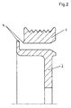
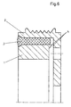
- FIGS. 1 to 6 The process indicated in FIGS. 1 to 6 is used for production the swing ring and the hub ring each have a one-piece material body Application consisting of metal and by forging, casting and / or a machining process is converted into a shape that the in the Figures 1 and 4 shown corresponds.
- the swing ring and the hub ring 1, 2 are in this case by a predetermined breaking point 4 of wedge-shaped narrowed profile temporarily trained and connected.
- the one-piece swing and Hub ring can be easily stored and shipped in this form.
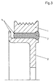
- FIGS. 2 and 5 show that the swing ring and the hub ring 1, 2 have been separated from each other by a relative axial displacement and now form two independent parts.
- the one to separate the Both parts required tensile or compressive forces cause non-cutting destruction the predetermined breaking point 4.
- the separation can be effected very quickly and doesn't produce splinters.
- the relative shift can be before or after Insert the rubber ring.
- Rubber ring 3 it is also possible to use an enclosed one instead Rubber ring 3 to use a vulcanized rubber ring. For this it is only necessary to insert the swing ring and the hub ring in one insert the appropriate vulcanization tool and in the remaining radial space between the two rings with a vulcanizable Fill rubber compound and solidify the rubber compound by vulcanization and connect with the two rings.
Landscapes
- Engineering & Computer Science (AREA)
- General Engineering & Computer Science (AREA)
- Physics & Mathematics (AREA)
- Acoustics & Sound (AREA)
- Aviation & Aerospace Engineering (AREA)
- Mechanical Engineering (AREA)
- Pulleys (AREA)
- Springs (AREA)
Claims (2)
- Procédé de fabrication d'un amortisseur de vibrations torsionnelles, dans lequel un volant et une frette de roue (1, 2) sont produits et reliés d'une manière permettant une torsion relative par l'insertion ultérieure d'un anneau en caoutchouc (3), caractérisé en ce que le volant et la frette de roue (1, 2) sont produits avec un point de rupture (4) sous forme d'une pièce en une partie au niveau de la transition, et en ce que le point de rupture (4) est détruit, avant ou après l'insertion de l'anneau en caoutchouc (3), sans prélèvement de matériau.
- Procédé selon la revendication 1, caractérisé en ce que la frette de roue et le volant (1, 2) sont soumis à une torsion relative dans la direction axiale pour détruire le point de rupture (4).
Applications Claiming Priority (2)
| Application Number | Priority Date | Filing Date | Title |
|---|---|---|---|
| DE19743686A DE19743686C2 (de) | 1997-10-02 | 1997-10-02 | Verfahren zur Herstellung eines Torsionsschwingungstilgers |
| DE19743686 | 1997-10-02 |
Publications (2)
| Publication Number | Publication Date |
|---|---|
| EP0907039A1 EP0907039A1 (fr) | 1999-04-07 |
| EP0907039B1 true EP0907039B1 (fr) | 2002-11-13 |
Family
ID=7844470
Family Applications (1)
| Application Number | Title | Priority Date | Filing Date |
|---|---|---|---|
| EP98113159A Expired - Lifetime EP0907039B1 (fr) | 1997-10-02 | 1998-07-15 | Procédure de fabrication d'un amortisseur de vibrations torsionelles |
Country Status (3)
| Country | Link |
|---|---|
| EP (1) | EP0907039B1 (fr) |
| CA (1) | CA2246058C (fr) |
| DE (2) | DE19743686C2 (fr) |
Families Citing this family (6)
| Publication number | Priority date | Publication date | Assignee | Title |
|---|---|---|---|---|
| DE60223924T2 (de) * | 2001-08-03 | 2008-10-23 | The Gates Corp., Denver | Kurbelwellendämpfer mit integrierter indexscheibe und herstellverfahren dafür |
| US7681559B2 (en) * | 2006-12-21 | 2010-03-23 | Eaton Corporation | Torsion damping mechanism for a supercharger |
| DE102007013300A1 (de) * | 2007-03-16 | 2008-09-18 | Linnig Trucktec Gmbh | Reibschaltkupplung |
| EP2140174B1 (fr) | 2007-04-18 | 2011-06-29 | Neumayer Tekfor Holding GMBH | Roue dentée |
| DE102013100450A1 (de) | 2013-01-17 | 2014-07-17 | Winkelmann Powertrain Components Gmbh & Co. Kg | Verfahren zur Herstellung eines Drehschwingungsdämpfers |
| JP6182978B2 (ja) * | 2013-05-24 | 2017-08-23 | 株式会社ジェイテクト | ダンパプーリの製造方法及びダンパプーリの製造装置 |
Family Cites Families (5)
| Publication number | Priority date | Publication date | Assignee | Title |
|---|---|---|---|---|
| JPS60141532A (ja) * | 1983-12-28 | 1985-07-26 | Toyoda Gosei Co Ltd | 金属ハウジング付防振ゴムの製造方法 |
| DE3535859A1 (de) * | 1985-10-08 | 1987-04-09 | Schaeffler Waelzlager Kg | Riemenscheibe mit daempfungselement |
| GB2233424B (en) * | 1989-06-29 | 1993-04-14 | Freudenberg Carl | Torsional vibration damper |
| DE4235074C1 (de) * | 1992-10-17 | 1993-11-11 | Freudenberg Carl Fa | Verfahren zur Herstellung eines Torsionsschwingungsdämpfers |
| DE4241156C1 (de) * | 1992-12-07 | 1994-04-07 | Metzeler Gimetall Ag | Verfahren zur Herstellung eines Drehschwingungsdämpfers |
-
1997
- 1997-10-02 DE DE19743686A patent/DE19743686C2/de not_active Expired - Lifetime
-
1998
- 1998-07-15 DE DE59806262T patent/DE59806262D1/de not_active Expired - Lifetime
- 1998-07-15 EP EP98113159A patent/EP0907039B1/fr not_active Expired - Lifetime
- 1998-09-30 CA CA002246058A patent/CA2246058C/fr not_active Expired - Fee Related
Also Published As
| Publication number | Publication date |
|---|---|
| DE19743686A1 (de) | 1999-04-15 |
| CA2246058C (fr) | 2002-09-24 |
| EP0907039A1 (fr) | 1999-04-07 |
| CA2246058A1 (fr) | 1999-04-02 |
| DE59806262D1 (de) | 2002-12-19 |
| DE19743686C2 (de) | 2000-01-05 |
Similar Documents
| Publication | Publication Date | Title |
|---|---|---|
| EP1005401B1 (fr) | Procede pour assembler deux elements de maniere detachable et systemes d'assemblage pour mettre ledit procede en oeuvre | |
| EP1963690B1 (fr) | Ecrou, procede de fabrication dudit ecrou et outil a cet effet | |
| DD295894A5 (de) | Verbindungsanordnung | |
| DE3828018C2 (de) | Verfahren zum Herstellen eines Verbundes aus einer metallenen Innenhülse und einem Rohr aus Faser- Kunststoff-Material sowie danach hergestellter Verbund | |
| DE3633435A1 (de) | Verfahren zur herstellung einer gebauten nockenwelle sowie gebaute nockenwelle aus einem wellenrohr und aufgeschobenen elementen | |
| DE19519798A1 (de) | Verfahren zur Herstellung geteilter Lager | |
| DE3513340A1 (de) | Mitnehmerverbindung zwischen einer welle und einer nabe | |
| DE102017104159A1 (de) | Zahnrad für eine Ausgleichswelle und eine Ausgleichswelle | |
| EP0032668A1 (fr) | Matrice pour le déformage dans le procédé à froid ou à demi-chaud | |
| EP0907039B1 (fr) | Procédure de fabrication d'un amortisseur de vibrations torsionelles | |
| DE102017011969A1 (de) | Verfahren zum Herstellen einer Rotoreinheit für einen Elektromotor | |
| DE102004001141B4 (de) | Verfahren zur Herstellung von Wellenzapfen und zur Herstellung einer gebauten Welle | |
| DE19915027A1 (de) | Getriebeteil und Verfahren zum Formen eines Getriebeteils | |
| DE602004009244T2 (de) | Antriebswelle | |
| DE3203438A1 (de) | Verfahren zur herstellung einer metallmuffe aus einem zylindrischen rohrabschnitt | |
| DE4300869B4 (de) | Drehschwingungsdämpfer, insbesondere für Kraftfahrzeuge | |
| EP0170877B1 (fr) | Rotor pour métier à filer à fibres libérées et son procédé de fabrication | |
| EP0464401B1 (fr) | Rotor de filage à bout ouvert | |
| DE2853230A1 (de) | Verfahren und gesenkwerkzeug zur herstellung einer gelenkhaelfte eines homokinetischen gelenkes | |
| EP1313591B1 (fr) | Procede pour faire subir une deformation plastique a un alesage de moyeu d'une piece a vitesse de rotation elevee d'une turbomachine | |
| EP0374389A2 (fr) | Procédé de traitement préalable de pièces pour un arbre à cames composé | |
| DE102015219855A1 (de) | Hohlrad mit Innenverzahnung und Kronenverzahnung, sowie Verfahren zu dessen Herstellung und Schaltgetriebe mit solchem Hohlrad | |
| DE19829104C1 (de) | Verfahren zum Verbinden eines Schwungrads einer Kupplung mit einem Kupplungsgehäuse | |
| EP3986633A1 (fr) | Pièce de base destinée à produire un boîtier de cartouche et boîtier de cartouche, procédé de production d'une pièce de base pour un boîtier de cartouche, et procédé de production d'un boîtier de cartouche | |
| EP1035349A2 (fr) | Support élastomérique avec butées axiales et méthode de fabrication d'un tel support |
Legal Events
| Date | Code | Title | Description |
|---|---|---|---|
| PUAI | Public reference made under article 153(3) epc to a published international application that has entered the european phase |
Free format text: ORIGINAL CODE: 0009012 |
|
| 17P | Request for examination filed |
Effective date: 19990112 |
|
| AK | Designated contracting states |
Kind code of ref document: A1 Designated state(s): DE FR GB IT |
|
| AX | Request for extension of the european patent |
Free format text: AL;LT;LV;MK;RO;SI |
|
| AKX | Designation fees paid |
Free format text: DE FR GB IT |
|
| RAP1 | Party data changed (applicant data changed or rights of an application transferred) |
Owner name: CARL FREUDENBERG KG |
|
| GRAG | Despatch of communication of intention to grant |
Free format text: ORIGINAL CODE: EPIDOS AGRA |
|
| GRAG | Despatch of communication of intention to grant |
Free format text: ORIGINAL CODE: EPIDOS AGRA |
|
| GRAH | Despatch of communication of intention to grant a patent |
Free format text: ORIGINAL CODE: EPIDOS IGRA |
|
| 17Q | First examination report despatched |
Effective date: 20020516 |
|
| GRAH | Despatch of communication of intention to grant a patent |
Free format text: ORIGINAL CODE: EPIDOS IGRA |
|
| GRAA | (expected) grant |
Free format text: ORIGINAL CODE: 0009210 |
|
| AK | Designated contracting states |
Kind code of ref document: B1 Designated state(s): DE FR GB IT |
|
| REG | Reference to a national code |
Ref country code: GB Ref legal event code: FG4D Free format text: NOT ENGLISH |
|
| REF | Corresponds to: |
Ref document number: 59806262 Country of ref document: DE Date of ref document: 20021219 |
|
| GBT | Gb: translation of ep patent filed (gb section 77(6)(a)/1977) |
Effective date: 20021209 |
|
| ET | Fr: translation filed | ||
| PLBE | No opposition filed within time limit |
Free format text: ORIGINAL CODE: 0009261 |
|
| STAA | Information on the status of an ep patent application or granted ep patent |
Free format text: STATUS: NO OPPOSITION FILED WITHIN TIME LIMIT |
|
| 26N | No opposition filed |
Effective date: 20030814 |
|
| REG | Reference to a national code |
Ref country code: FR Ref legal event code: PLFP Year of fee payment: 19 |
|
| REG | Reference to a national code |
Ref country code: DE Ref legal event code: R081 Ref document number: 59806262 Country of ref document: DE Owner name: VIBRACOUSTIC GMBH, DE Free format text: FORMER OWNER: CARL FREUDENBERG KG, 69469 WEINHEIM, DE |
|
| REG | Reference to a national code |
Ref country code: FR Ref legal event code: PLFP Year of fee payment: 20 |
|
| PGFP | Annual fee paid to national office [announced via postgrant information from national office to epo] |
Ref country code: GB Payment date: 20170724 Year of fee payment: 20 Ref country code: FR Payment date: 20170720 Year of fee payment: 20 Ref country code: IT Payment date: 20170721 Year of fee payment: 20 Ref country code: DE Payment date: 20170731 Year of fee payment: 20 |
|
| REG | Reference to a national code |
Ref country code: DE Ref legal event code: R071 Ref document number: 59806262 Country of ref document: DE |
|
| REG | Reference to a national code |
Ref country code: GB Ref legal event code: PE20 Expiry date: 20180714 |
|
| PG25 | Lapsed in a contracting state [announced via postgrant information from national office to epo] |
Ref country code: GB Free format text: LAPSE BECAUSE OF EXPIRATION OF PROTECTION Effective date: 20180714 |