EP0907039B1 - Process for the manufacture of a torsional vibration damper - Google Patents
Process for the manufacture of a torsional vibration damper Download PDFInfo
- Publication number
- EP0907039B1 EP0907039B1 EP98113159A EP98113159A EP0907039B1 EP 0907039 B1 EP0907039 B1 EP 0907039B1 EP 98113159 A EP98113159 A EP 98113159A EP 98113159 A EP98113159 A EP 98113159A EP 0907039 B1 EP0907039 B1 EP 0907039B1
- Authority
- EP
- European Patent Office
- Prior art keywords
- ring
- torsional vibration
- hub
- vibration damper
- predetermined breaking
- Prior art date
- Legal status (The legal status is an assumption and is not a legal conclusion. Google has not performed a legal analysis and makes no representation as to the accuracy of the status listed.)
- Expired - Lifetime
Links
Images


Classifications
-
- F—MECHANICAL ENGINEERING; LIGHTING; HEATING; WEAPONS; BLASTING
- F16—ENGINEERING ELEMENTS AND UNITS; GENERAL MEASURES FOR PRODUCING AND MAINTAINING EFFECTIVE FUNCTIONING OF MACHINES OR INSTALLATIONS; THERMAL INSULATION IN GENERAL
- F16F—SPRINGS; SHOCK-ABSORBERS; MEANS FOR DAMPING VIBRATION
- F16F15/00—Suppression of vibrations in systems; Means or arrangements for avoiding or reducing out-of-balance forces, e.g. due to motion
- F16F15/10—Suppression of vibrations in rotating systems by making use of members moving with the system
- F16F15/12—Suppression of vibrations in rotating systems by making use of members moving with the system using elastic members or friction-damping members, e.g. between a rotating shaft and a gyratory mass mounted thereon
- F16F15/121—Suppression of vibrations in rotating systems by making use of members moving with the system using elastic members or friction-damping members, e.g. between a rotating shaft and a gyratory mass mounted thereon using springs as elastic members, e.g. metallic springs
- F16F15/124—Elastomeric springs
- F16F15/126—Elastomeric springs consisting of at least one annular element surrounding the axis of rotation
-
- F—MECHANICAL ENGINEERING; LIGHTING; HEATING; WEAPONS; BLASTING
- F16—ENGINEERING ELEMENTS AND UNITS; GENERAL MEASURES FOR PRODUCING AND MAINTAINING EFFECTIVE FUNCTIONING OF MACHINES OR INSTALLATIONS; THERMAL INSULATION IN GENERAL
- F16F—SPRINGS; SHOCK-ABSORBERS; MEANS FOR DAMPING VIBRATION
- F16F15/00—Suppression of vibrations in systems; Means or arrangements for avoiding or reducing out-of-balance forces, e.g. due to motion
- F16F15/10—Suppression of vibrations in rotating systems by making use of members moving with the system
- F16F15/14—Suppression of vibrations in rotating systems by making use of members moving with the system using masses freely rotating with the system, i.e. uninvolved in transmitting driveline torque, e.g. rotative dynamic dampers
- F16F15/1407—Suppression of vibrations in rotating systems by making use of members moving with the system using masses freely rotating with the system, i.e. uninvolved in transmitting driveline torque, e.g. rotative dynamic dampers the rotation being limited with respect to the driving means
- F16F15/1414—Masses driven by elastic elements
- F16F15/1435—Elastomeric springs, i.e. made of plastic or rubber
- F16F15/1442—Elastomeric springs, i.e. made of plastic or rubber with a single mass
-
- F—MECHANICAL ENGINEERING; LIGHTING; HEATING; WEAPONS; BLASTING
- F16—ENGINEERING ELEMENTS AND UNITS; GENERAL MEASURES FOR PRODUCING AND MAINTAINING EFFECTIVE FUNCTIONING OF MACHINES OR INSTALLATIONS; THERMAL INSULATION IN GENERAL
- F16F—SPRINGS; SHOCK-ABSORBERS; MEANS FOR DAMPING VIBRATION
- F16F2226/00—Manufacturing; Treatments
- F16F2226/04—Assembly or fixing methods; methods to form or fashion parts
-
- F—MECHANICAL ENGINEERING; LIGHTING; HEATING; WEAPONS; BLASTING
- F16—ENGINEERING ELEMENTS AND UNITS; GENERAL MEASURES FOR PRODUCING AND MAINTAINING EFFECTIVE FUNCTIONING OF MACHINES OR INSTALLATIONS; THERMAL INSULATION IN GENERAL
- F16H—GEARING
- F16H55/00—Elements with teeth or friction surfaces for conveying motion; Worms, pulleys or sheaves for gearing mechanisms
- F16H55/32—Friction members
- F16H55/36—Pulleys
- F16H2055/366—Pulleys with means providing resilience or vibration damping
Definitions
- the invention relates to a method for producing a torsional vibration damper, in which a swing ring and a hub ring are generated and by subsequent Inserting a rubber ring can be connected relatively rotatable.
- the invention has for its object a method for producing a To show torsional vibration damper that is less expensive than the known method.
- the momentum and the hub ring in shape with a predetermined breaking point at the transition zone a single piece is generated and that the predetermined breaking point for generation independent parts before or after inserting the rubber ring without Material removal is destroyed.
- the hub and the flywheel can be used Destruction of the predetermined breaking point can be moved relatively in the axial direction, for example using tensile and / or compressive forces.
- the hub and flywheel rings can also be used as closed unit can be transported and stored until the final one Pressing in the rubber ring. In terms of handling, that's great Advantage.
- the destruction of the predetermined breaking point can possibly in the Work step of inserting the rubber ring to be integrated and this step facilitate if necessary.
- both Generate torsional vibration absorbers in which the flywheel ring is the hub ring encloses on the outside as well as those in which the flywheel on the Is arranged inside the hub ring. Furthermore, the use of the generation of combined designs possible, both a flywheel have on the outside as well as on the inside.
- the opposing boundary surfaces of the in the radial direction Swing and the hub ring, which during the intended Use limit the rubber ring are usually cylindrical educated. Different designs are easily possible, for example bell-shaped profiles.
- the tensionless destruction of the The predetermined breaking points require that the swing ring and the hub ring forming material has a certain brittleness.
- the use of ferrous materials has proven to be suitable.
- the predetermined breaking point between the swing ring and the hub ring has expedient a wedge-shaped tapered profile to ensure that the desired one Destruction before or after inserting the rubber ring on a very precise defined place and avoiding material detachment.
- Ready-to-use torsional vibration damper is always the breaking edge of one radially projecting surface of the flywheel or hub ring is overlapped, whereby it is excluded that inadvertent handling in the proximity of the torsional vibration absorber, for example for repairs adjacent parts may be necessary, risk of injury to people results.
- the external appearance can otherwise that of the known Torsion damper match. It is therefore easily possible on the outside of the swing or the hub ring to attach a tooth or groove profile to the ready-to-use torsional vibration damper using a belt drive to connect with secondary aggregates.
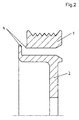
- FIGS. 1 to 6 The process indicated in FIGS. 1 to 6 is used for production the swing ring and the hub ring each have a one-piece material body Application consisting of metal and by forging, casting and / or a machining process is converted into a shape that the in the Figures 1 and 4 shown corresponds.
- the swing ring and the hub ring 1, 2 are in this case by a predetermined breaking point 4 of wedge-shaped narrowed profile temporarily trained and connected.
- the one-piece swing and Hub ring can be easily stored and shipped in this form.
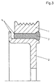
- FIGS. 2 and 5 show that the swing ring and the hub ring 1, 2 have been separated from each other by a relative axial displacement and now form two independent parts.
- the one to separate the Both parts required tensile or compressive forces cause non-cutting destruction the predetermined breaking point 4.
- the separation can be effected very quickly and doesn't produce splinters.
- the relative shift can be before or after Insert the rubber ring.
- Rubber ring 3 it is also possible to use an enclosed one instead Rubber ring 3 to use a vulcanized rubber ring. For this it is only necessary to insert the swing ring and the hub ring in one insert the appropriate vulcanization tool and in the remaining radial space between the two rings with a vulcanizable Fill rubber compound and solidify the rubber compound by vulcanization and connect with the two rings.
Description
Die Erfindung betrifft ein Verfahren zur Herstellung eines Torsionsschwingungstilgers, bei dem ein Schwung- und ein Nabenring erzeugt und durch nachträgliches Einfügen eines Gummiringes relativ verdrehbar verbunden werden.The invention relates to a method for producing a torsional vibration damper, in which a swing ring and a hub ring are generated and by subsequent Inserting a rubber ring can be connected relatively rotatable.
Ein solches Verfahren ist aus der Patentschrift DE 4235074 C1 bekannt. Der Schwung- und der Nabenring werden dabei unabhängig von einander erzeugt und durch nachträgliches Einfügen des Gummiringes relativ verdrehbar aneinander festgelegt. Die unabhängige Erzeugung des Naben- und des Schwungringes in Gestalt unabhängiger Einzelteile ist mit erheblichem Aufwand verbunden.Such a method is known from the patent DE 4235074 C1. The swing ring and the hub ring are generated independently of each other and by inserting the Rubber ring set relatively rotatable to each other. The independent Generation of the hub and the flywheel in the form of independent Items are associated with considerable effort.
Der Erfindung liegt die Aufgabe zugrunde, ein Verfahren zur Herstellung eines Torsionsschwingungstilgers zu zeigen, das kostengünstiger durchführbar ist als das bekannte Verfahren.The invention has for its object a method for producing a To show torsional vibration damper that is less expensive than the known method.
Diese Aufgabe wird erfindungsgemäß bei einem Verfahren der eingangs
genannten Art mit den kennzeichnenden Merkmalen von Anspruch 1 gelöst. Auf
eine vorteilhafte Ausgestaltung nimmt Anspruch 2 bezug. This object is achieved according to the invention in a method of the beginning
said type solved with the characterizing features of
Bei dem erfindungsgemäßen Verfahren ist es vorgesehen, daß der Schwungund der Nabenring mit einer Sollbruchstelle an der Übergangszone in Gestalt eines einzigen Stücks erzeugt wird und daß die Sollbruchstelle zur Erzeugung unabhängiger Teile vor oder nach dem Einfügen des Gummirings ohne Werkstoffentnahme zerstört wird. Der Naben- und der Schwungring können zur Zerstörung der Sollbruchstelle in axialer Richtung relativ verschoben werden, beispielsweise unter Anwendung von Zug- und/oder Druckkräften.In the method according to the invention it is provided that the momentum and the hub ring in shape with a predetermined breaking point at the transition zone a single piece is generated and that the predetermined breaking point for generation independent parts before or after inserting the rubber ring without Material removal is destroyed. The hub and the flywheel can be used Destruction of the predetermined breaking point can be moved relatively in the axial direction, for example using tensile and / or compressive forces.
Durch die gemeinsame Herstellung des Schwung- und des Nabenringes in Form eines einzigen Stücks besteht die Möglichkeit, die im gebrauchsfertigen Torsionsschwingungstilger einander radialer Richtung umschließenden Flächen, die gemeinsam den den Gummiring aufnehmenden Spalt begrenzen, im selben Arbeitsschritt gemeinsam zu erzeugen, beispielsweise durch eine spahnabhebende Bearbeitung, die sich zugleich auf beide Oberflächen auswirkt. Dadurch ist es ausgeschlossen, daß sich ungünstige Tollerierungen der jeweiligen Durchmesser ungünstig überlagern dergestalt, daß auf dem nachträglich angepreßten Gummiring nicht mehr die zu seiner Festlegung notwendige, radiale Anpressung ausgeübt wird. Die radiale Verpressung des Gummiringes läßt sich hierdurch bei dem erfindungsgemäßen Torsionsschwingungsdämpfers wesentlich besser kontrollieren als bei den Torsionsschwingungstilgern nach dem Stand der Technik. Für die Erzielung einer großen Gebrauchsdauer ist das von großem Vorteil.By jointly producing the swing ring and the hub ring in shape of a single piece there is the possibility in the ready to use Torsional vibration damper surfaces enclosing each other in the radial direction, which together limit the gap receiving the rubber ring, in the same Generate work step together, for example, by a path-lifting Machining that affects both surfaces at the same time. Thereby it is excluded that there are unfavorable tolerances of the respective diameter unfavorably overlay such that on the subsequently pressed The rubber ring no longer has the radial pressure required to fix it is exercised. This allows the radial compression of the rubber ring control the torsional vibration damper according to the invention much better than with the torsional vibration absorbers according to the prior art. This is of great advantage in order to achieve a long service life.
Durch die gemeinsame Herstellung des Schwung- und des Nabenringes in einer einzigen Herstellungsoperation ergibt sich außerdem eine deutliche Verminderung der Herstellkosten. Der Naben- und der Schwungring können außerdem als geschlossene Einheit transportiert und gelagert werden bis zur endgültigen Einpressung des Gummiringes. Hinsichtlich des handling ist das von großem Vorteil. Außerdem kann die Zerstörung der Sollbruchstelle gegebenenfalls in den Arbeitsschritt des Einfügens des Gummiringes integriert sein und diesen Schritt gegebenenfalls erleichtern.By jointly producing the swing ring and the hub ring in one single manufacturing operation there is also a significant reduction the manufacturing cost. The hub and flywheel rings can also be used as closed unit can be transported and stored until the final one Pressing in the rubber ring. In terms of handling, that's great Advantage. In addition, the destruction of the predetermined breaking point can possibly in the Work step of inserting the rubber ring to be integrated and this step facilitate if necessary.
Unter Verwendung des erfindungsgemäßen Verfahrens lassen sich sowohl Torsionsschwingungstilger erzeugen, bei denen der Schwungring den Nabenring außenseitig umschließt als auch solche, bei denen der Schwungring auf der Innenseite des Nabenrings angeordnet ist. Desweiteren ist die Verwendung bei der Erzeugung kombinierter Bauformen möglich, die einen Schwungring sowohl auf der Außen- als auch auf der Innenseite haben.Using the method according to the invention, both Generate torsional vibration absorbers in which the flywheel ring is the hub ring encloses on the outside as well as those in which the flywheel on the Is arranged inside the hub ring. Furthermore, the use of the generation of combined designs possible, both a flywheel have on the outside as well as on the inside.
Die einander in radialer Richtung gegenüberliegenden Begrenzungsflächen des Schwung- und des Nabenringes, welche während der bestimmungsgemäßen Verwendung den Gummiring begrenzen, sind normalerweise zylindrisch ausgebildet. Abweichende Gestaltungen sind ohne weiteres möglich, beispielsweise glockenkurven förmige Profile.The opposing boundary surfaces of the in the radial direction Swing and the hub ring, which during the intended Use limit the rubber ring are usually cylindrical educated. Different designs are easily possible, for example bell-shaped profiles.
Die erfindungsgemäß zur Anwendung gelangende, spannlose Zerstörung der Sollbruchstellen setzt voraus, daß der den Schwung- und den Nabenring bildende Werkstoffkörper eine gewisse Sprödigkeit aufweist. Als besonders geeignet hat sich die Verwendung von Eisenwerkstoffen bewährt.The tensionless destruction of the The predetermined breaking points require that the swing ring and the hub ring forming material has a certain brittleness. As special The use of ferrous materials has proven to be suitable.
Die Sollbruchstelle zwischen dem Schwung- und dem Nabenring hat zweckmäßig ein keilförmig zugespitztes Profil, um sicherzustellen, daß die gewollte Zerstörung vor oder nach dem Einfügen des Gummiringes an einer ganz präzise definierten Stelle und unter Vermeidung von Werkstoffablösungen erfolgt. In dem gebrauchsfertigen Torsionsschwingungstilger wird die Bruchkante stets von einer radial vorstehenden Fläche des Schwung- oder des Nabenringes übergriffen, wodurch es ausgeschlossen ist, daß sich bei einer unachtsamen Handhabung in der Nähe des Torsionsschwingunstilgers, die beispielsweise bei Reparaturen benachbarter Teilen erforderlich sein kann, eine Verletzungsgefahr für Personen ergibt. Das äußere Erscheinungsbild kann ansonsten demjenigen der bekannten Torsionstilger entsprechen. Es ist somit problemlos möglich, auf der Außenseite des Schwung- bzw. des Nabenringes ein Zahn- oder Rillenprofil anzubringen, um den gebrauchsfertigen Torsionsschwingungstilger mittels eines Riementriebes mit sekundären Aggregaten zu verbinden.The predetermined breaking point between the swing ring and the hub ring has expedient a wedge-shaped tapered profile to ensure that the desired one Destruction before or after inserting the rubber ring on a very precise defined place and avoiding material detachment. By doing Ready-to-use torsional vibration damper is always the breaking edge of one radially projecting surface of the flywheel or hub ring is overlapped, whereby it is excluded that inadvertent handling in the proximity of the torsional vibration absorber, for example for repairs adjacent parts may be necessary, risk of injury to people results. The external appearance can otherwise that of the known Torsion damper match. It is therefore easily possible on the outside of the swing or the hub ring to attach a tooth or groove profile to the ready-to-use torsional vibration damper using a belt drive to connect with secondary aggregates.
Das erfindungsgemäße Verfahren wird nachfolgend anhand der Zeichnung weiter verdeutlicht. Es zeigen:
Figuren 1 bis 3- ein Verfahren zur Herstellung eines Torsionsschwingungstilgers, bei dem der Schwungring den Nabenring in radialer Richtung außenseitig umschließt.
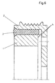
Figuren 4 bis 6- ein Verfahren zur Herstellung eines Torsionsschwingungstilgers, bei dem der Nabenring den Schwungring in radialer Richtung außenseitig umschließt.
- Figures 1 to 3
- a method for producing a torsional vibration damper, in which the flywheel encloses the hub ring in the radial direction on the outside.
- Figures 4 to 6
- a method for producing a torsional vibration damper, in which the hub ring encloses the outside of the flywheel in the radial direction.
Bei dem in den Figuren 1 bis 6 angedeuteten Verfahren gelangt zur Herstellung
des Schwung- und des Nabenringes jeweils ein einstückiger Werkstoffkörper zu
Anwendung, der aus Metall besteht und durch Schmieden, Gießen und / oder
eine spanabhebende Bearbeitung in eine Gestalt überführt wird, die der in den
Figuren 1 bzw. 4 gezeigten entspricht. Der Schwung- und der Nabenring 1, 2
sind dabei durch eine Sollbruchstelle 4 von keilförmig verengtem Profil in einander
übergehend ausgebildet und verbunden. Der somit einstückige Schwungund
Nabenring können in dieser Form leicht gelagert und versandt werden. The process indicated in FIGS. 1 to 6 is used for production
the swing ring and the hub ring each have a one-piece material body
Application consisting of metal and by forging, casting and / or
a machining process is converted into a shape that the in the
Figures 1 and 4 shown corresponds. The swing ring and the
In den Figuren 2 und 5 wird gezeigt, daß der Schwung- und der Nabenring 1, 2
durch eine relative Axialverschiebung von einander getrennt worden sind und
nunmehr zwei von einander unabhängige Teile bilden. Die zur Trennung der
beiden Teile benötigten Zug- bzw. Druckkräfte bewirken eine spanlose Zerstörung
der Sollbruchstelle 4. Die Trennung kann sehr schnell bewirkt werden
und erzeugt keine Splitter. Die Relativverschiebung kann vor oder nach dem
Einfügen des Gummirings vorgenommen werden.FIGS. 2 and 5 show that the swing ring and the
In den Figuren 3 und 6 werden zwei Ausführungen eines gebrauchsfertigen
Torsionsschwingungstilgers gezeigt, bei denen in dem radialen Zwischenraum
zwischen dem Schwungring 1 und dem Nabenring 2 ein Gummiring 3 unter
elastischer Deformierung eingepreßt ist. Die radiale Verpressung des
Gummiringes 3 ist dabei so bemessen, daß sich während einer relativen
Verdrehung des Schwungringes 1 in bezug den Nabenring 2 keinerlei gleitende
Bewegung ergibt. Die gesamte relative Verdrehung des Schwungringes 1 in
bezug auf den Nabenring 2 wird ausschließlich durch eine elastische
Deformierung des Gummiringes 3 aufgenommen und hat den Zweck, die
anregende Schwingung zu vermindern.In Figures 3 and 6, two versions of a ready to use
Torsional vibration damper shown in the radial gap
a
Selbstverständlich ist es ebenfalls möglich, anstelle eines eingeschlossenen
Gummiringes 3 einen unmittelbar einvulkanisierten Gummiring zu verwenden.
Hierzu ist es lediglich erforderlich, den Schwung- und den Nabenring in ein
entsprechendes Vulkanisationswerkzeug einzulegen und in den verbleibenden,
radialen Zwischenraum zwischen beiden Ringen mit einer vulkanisierbaren
Gummimasse zu füllen und die Gummimasse durch Vulkanisation zu verfestigen
und mit den beiden Ringen zu verbinden.Of course, it is also possible to use an enclosed one instead
Rubber
Claims (2)
- A method for the production of a torsional vibration absorber, in which a fly ring and a hub ring (1, 2) are produced and connected in a manner that allows relative rotation by subsequent insertion of a rubber ring (3), characterized in that the fly ring and the hub ring (1, 2) are produced with a predetermined breaking point (4) at the transition in the form of a one-piece workpiece, and in that the predetermined breaking point (4) is destroyed without removal of material before or after the insertion of the rubber ring (3).
- A method according to claim 1, characterized in that the hub ring and the fly ring (1, 2) are subjected to relative displacement in the axial direction to destroy the predetermined breaking point (4).
Applications Claiming Priority (2)
| Application Number | Priority Date | Filing Date | Title |
|---|---|---|---|
| DE19743686A DE19743686C2 (en) | 1997-10-02 | 1997-10-02 | Process for producing a torsional vibration damper |
| DE19743686 | 1997-10-02 |
Publications (2)
| Publication Number | Publication Date |
|---|---|
| EP0907039A1 EP0907039A1 (en) | 1999-04-07 |
| EP0907039B1 true EP0907039B1 (en) | 2002-11-13 |
Family
ID=7844470
Family Applications (1)
| Application Number | Title | Priority Date | Filing Date |
|---|---|---|---|
| EP98113159A Expired - Lifetime EP0907039B1 (en) | 1997-10-02 | 1998-07-15 | Process for the manufacture of a torsional vibration damper |
Country Status (3)
| Country | Link |
|---|---|
| EP (1) | EP0907039B1 (en) |
| CA (1) | CA2246058C (en) |
| DE (2) | DE19743686C2 (en) |
Families Citing this family (6)
| Publication number | Priority date | Publication date | Assignee | Title |
|---|---|---|---|---|
| WO2003014596A1 (en) * | 2001-08-03 | 2003-02-20 | The Gates Corporation | Crankshaft damper with integral pulse ring and method for production |
| US7681559B2 (en) * | 2006-12-21 | 2010-03-23 | Eaton Corporation | Torsion damping mechanism for a supercharger |
| DE102007013300A1 (en) * | 2007-03-16 | 2008-09-18 | Linnig Trucktec Gmbh | Friction clutch for fan wheel of motor vehicle, has damping device that is arranged between rotor and fan wheel of motor vehicle, where damping device has pretensioned gasket, and fan wheel of motor vehicle is connected with anchor disk |
| EP2140174B1 (en) | 2007-04-18 | 2011-06-29 | Neumayer Tekfor Holding GMBH | Toothed gear |
| DE102013100450A1 (en) | 2013-01-17 | 2014-07-17 | Winkelmann Powertrain Components Gmbh & Co. Kg | Method for producing a torsional vibration damper |
| JP6182978B2 (en) * | 2013-05-24 | 2017-08-23 | 株式会社ジェイテクト | Damper pulley manufacturing method and damper pulley manufacturing apparatus |
Family Cites Families (5)
| Publication number | Priority date | Publication date | Assignee | Title |
|---|---|---|---|---|
| JPS60141532A (en) * | 1983-12-28 | 1985-07-26 | Toyoda Gosei Co Ltd | Manufacture of rubber spring with metal housing |
| DE3535859A1 (en) * | 1985-10-08 | 1987-04-09 | Schaeffler Waelzlager Kg | PULLEY WITH DAMPING ELEMENT |
| GB2233424B (en) * | 1989-06-29 | 1993-04-14 | Freudenberg Carl | Torsional vibration damper |
| DE4235074C1 (en) * | 1992-10-17 | 1993-11-11 | Freudenberg Carl Fa | Method of manufacturing a torsional vibration damper |
| DE4241156C1 (en) * | 1992-12-07 | 1994-04-07 | Metzeler Gimetall Ag | Production method for torsional vibration damper of IC engine crankshaft - involves producing single metal component which after introduction of rubber spring element has end face machined off to leave damper in completed form |
-
1997
- 1997-10-02 DE DE19743686A patent/DE19743686C2/en not_active Expired - Lifetime
-
1998
- 1998-07-15 EP EP98113159A patent/EP0907039B1/en not_active Expired - Lifetime
- 1998-07-15 DE DE59806262T patent/DE59806262D1/en not_active Expired - Lifetime
- 1998-09-30 CA CA002246058A patent/CA2246058C/en not_active Expired - Fee Related
Also Published As
| Publication number | Publication date |
|---|---|
| DE59806262D1 (en) | 2002-12-19 |
| CA2246058C (en) | 2002-09-24 |
| DE19743686A1 (en) | 1999-04-15 |
| DE19743686C2 (en) | 2000-01-05 |
| CA2246058A1 (en) | 1999-04-02 |
| EP0907039A1 (en) | 1999-04-07 |
Similar Documents
| Publication | Publication Date | Title |
|---|---|---|
| EP1963690B1 (en) | Screw nut, method of production thereof and corresponding tool | |
| EP1005401B1 (en) | Method for removably connecting two members and connection systems for realising the same | |
| DD295894A5 (en) | CONNECTION ARRANGEMENT | |
| EP0265663A1 (en) | Method of producing a camshaft, as well as a camshaft made from a tube, and elements placed thereon | |
| EP1108483B1 (en) | Method and device for flow-turning | |
| DE102017104159A1 (en) | Gear for a balance shaft and a balance shaft | |
| DE3513340A1 (en) | Driving connection between a shaft and a hub | |
| EP0907039B1 (en) | Process for the manufacture of a torsional vibration damper | |
| DE102004001141B4 (en) | Method for producing shaft journals and for producing a built shaft | |
| EP0032668A1 (en) | Cold-process or semicold-process massive-forming die | |
| DE19915027A1 (en) | Forming gear element for starter motor, and resultant gear element, with successively diminishing wall thickness of element obtained by combined radial and axial motion of at least one adjustable roll of pressure rolling machine | |
| DE602004009244T2 (en) | drive shaft | |
| DE3203438A1 (en) | METHOD FOR PRODUCING A METAL SLEEVE FROM A CYLINDRICAL PIPE SECTION | |
| DE4300869B4 (en) | Torsional vibration damper, in particular for motor vehicles | |
| DE102006057485A1 (en) | Synchronizing body/detent on a synchronizing device for a change speed gear forms a ring around an axis of symmetry with an inner hub and inner toothed gearing | |
| EP0464401B1 (en) | Open-ended spinning rotor | |
| DE2853230A1 (en) | METHOD AND MOLDING TOOL FOR PRODUCING A JOINT HALF OF A HOMOKINETIC JOINT | |
| EP0170877B1 (en) | Open-end spinning rotor and method of producing it | |
| EP0374389A2 (en) | Process for the pretreatment of parts for a composite camshaft | |
| DE102005060490A1 (en) | Rubber mount for motor vehicle comfort has bearing body and outer part that are axially divided in two and only combined with inner part at point of fitting to form rubber mount | |
| EP1313591B1 (en) | Method for the plastic moulding of the hub recess for a fast running turbine component | |
| EP1035349A2 (en) | Elastomeric support with axial end-stops and manufacturing process therefor | |
| DE19928648A1 (en) | Process to press-fit assemble automotive clutch flywheel and housing is simpler and prior art and more reliable | |
| DE102021002526B3 (en) | Method for producing a hollow shaft, a hollow shaft produced therewith and a related shaping tool | |
| DE102010052875A1 (en) | Method for manufacturing constant velocity joint e.g. fixed joint, for motor car, involves obtaining joint outer part with tracks from radial outer portion after processing separation of radial inner portion from radial outer portion |
Legal Events
| Date | Code | Title | Description |
|---|---|---|---|
| PUAI | Public reference made under article 153(3) epc to a published international application that has entered the european phase |
Free format text: ORIGINAL CODE: 0009012 |
|
| 17P | Request for examination filed |
Effective date: 19990112 |
|
| AK | Designated contracting states |
Kind code of ref document: A1 Designated state(s): DE FR GB IT |
|
| AX | Request for extension of the european patent |
Free format text: AL;LT;LV;MK;RO;SI |
|
| AKX | Designation fees paid |
Free format text: DE FR GB IT |
|
| RAP1 | Party data changed (applicant data changed or rights of an application transferred) |
Owner name: CARL FREUDENBERG KG |
|
| GRAG | Despatch of communication of intention to grant |
Free format text: ORIGINAL CODE: EPIDOS AGRA |
|
| GRAG | Despatch of communication of intention to grant |
Free format text: ORIGINAL CODE: EPIDOS AGRA |
|
| GRAH | Despatch of communication of intention to grant a patent |
Free format text: ORIGINAL CODE: EPIDOS IGRA |
|
| 17Q | First examination report despatched |
Effective date: 20020516 |
|
| GRAH | Despatch of communication of intention to grant a patent |
Free format text: ORIGINAL CODE: EPIDOS IGRA |
|
| GRAA | (expected) grant |
Free format text: ORIGINAL CODE: 0009210 |
|
| AK | Designated contracting states |
Kind code of ref document: B1 Designated state(s): DE FR GB IT |
|
| REG | Reference to a national code |
Ref country code: GB Ref legal event code: FG4D Free format text: NOT ENGLISH |
|
| REF | Corresponds to: |
Ref document number: 59806262 Country of ref document: DE Date of ref document: 20021219 |
|
| GBT | Gb: translation of ep patent filed (gb section 77(6)(a)/1977) |
Effective date: 20021209 |
|
| ET | Fr: translation filed | ||
| PLBE | No opposition filed within time limit |
Free format text: ORIGINAL CODE: 0009261 |
|
| STAA | Information on the status of an ep patent application or granted ep patent |
Free format text: STATUS: NO OPPOSITION FILED WITHIN TIME LIMIT |
|
| 26N | No opposition filed |
Effective date: 20030814 |
|
| REG | Reference to a national code |
Ref country code: FR Ref legal event code: PLFP Year of fee payment: 19 |
|
| REG | Reference to a national code |
Ref country code: DE Ref legal event code: R081 Ref document number: 59806262 Country of ref document: DE Owner name: VIBRACOUSTIC GMBH, DE Free format text: FORMER OWNER: CARL FREUDENBERG KG, 69469 WEINHEIM, DE |
|
| REG | Reference to a national code |
Ref country code: FR Ref legal event code: PLFP Year of fee payment: 20 |
|
| PGFP | Annual fee paid to national office [announced via postgrant information from national office to epo] |
Ref country code: GB Payment date: 20170724 Year of fee payment: 20 Ref country code: FR Payment date: 20170720 Year of fee payment: 20 Ref country code: IT Payment date: 20170721 Year of fee payment: 20 Ref country code: DE Payment date: 20170731 Year of fee payment: 20 |
|
| REG | Reference to a national code |
Ref country code: DE Ref legal event code: R071 Ref document number: 59806262 Country of ref document: DE |
|
| REG | Reference to a national code |
Ref country code: GB Ref legal event code: PE20 Expiry date: 20180714 |
|
| PG25 | Lapsed in a contracting state [announced via postgrant information from national office to epo] |
Ref country code: GB Free format text: LAPSE BECAUSE OF EXPIRATION OF PROTECTION Effective date: 20180714 |