EP0906850B1 - Steuereinrichtung der Leuchtrichtung eines Kfz-Scheinwerfers - Google Patents
Steuereinrichtung der Leuchtrichtung eines Kfz-Scheinwerfers Download PDFInfo
- Publication number
- EP0906850B1 EP0906850B1 EP98118432A EP98118432A EP0906850B1 EP 0906850 B1 EP0906850 B1 EP 0906850B1 EP 98118432 A EP98118432 A EP 98118432A EP 98118432 A EP98118432 A EP 98118432A EP 0906850 B1 EP0906850 B1 EP 0906850B1
- Authority
- EP
- European Patent Office
- Prior art keywords
- vehicle
- optical beam
- beam axis
- stroke sensors
- traveling
- Prior art date
- Legal status (The legal status is an assumption and is not a legal conclusion. Google has not performed a legal analysis and makes no representation as to the accuracy of the status listed.)
- Expired - Lifetime
Links
Images


Classifications
-
- B—PERFORMING OPERATIONS; TRANSPORTING
- B60—VEHICLES IN GENERAL
- B60Q—ARRANGEMENT OF SIGNALLING OR LIGHTING DEVICES, THE MOUNTING OR SUPPORTING THEREOF OR CIRCUITS THEREFOR, FOR VEHICLES IN GENERAL
- B60Q1/00—Arrangement of optical signalling or lighting devices, the mounting or supporting thereof or circuits therefor
- B60Q1/02—Arrangement of optical signalling or lighting devices, the mounting or supporting thereof or circuits therefor the devices being primarily intended to illuminate the way ahead or to illuminate other areas of way or environments
- B60Q1/04—Arrangement of optical signalling or lighting devices, the mounting or supporting thereof or circuits therefor the devices being primarily intended to illuminate the way ahead or to illuminate other areas of way or environments the devices being headlights
- B60Q1/06—Arrangement of optical signalling or lighting devices, the mounting or supporting thereof or circuits therefor the devices being primarily intended to illuminate the way ahead or to illuminate other areas of way or environments the devices being headlights adjustable, e.g. remotely-controlled from inside vehicle
- B60Q1/08—Arrangement of optical signalling or lighting devices, the mounting or supporting thereof or circuits therefor the devices being primarily intended to illuminate the way ahead or to illuminate other areas of way or environments the devices being headlights adjustable, e.g. remotely-controlled from inside vehicle automatically
- B60Q1/10—Arrangement of optical signalling or lighting devices, the mounting or supporting thereof or circuits therefor the devices being primarily intended to illuminate the way ahead or to illuminate other areas of way or environments the devices being headlights adjustable, e.g. remotely-controlled from inside vehicle automatically due to vehicle inclination, e.g. due to load distribution
- B60Q1/115—Arrangement of optical signalling or lighting devices, the mounting or supporting thereof or circuits therefor the devices being primarily intended to illuminate the way ahead or to illuminate other areas of way or environments the devices being headlights adjustable, e.g. remotely-controlled from inside vehicle automatically due to vehicle inclination, e.g. due to load distribution by electric means
-
- B—PERFORMING OPERATIONS; TRANSPORTING
- B60—VEHICLES IN GENERAL
- B60Q—ARRANGEMENT OF SIGNALLING OR LIGHTING DEVICES, THE MOUNTING OR SUPPORTING THEREOF OR CIRCUITS THEREFOR, FOR VEHICLES IN GENERAL
- B60Q2300/00—Indexing codes for automatically adjustable headlamps or automatically dimmable headlamps
- B60Q2300/10—Indexing codes relating to particular vehicle conditions
- B60Q2300/11—Linear movements of the vehicle
- B60Q2300/112—Vehicle speed
-
- B—PERFORMING OPERATIONS; TRANSPORTING
- B60—VEHICLES IN GENERAL
- B60Q—ARRANGEMENT OF SIGNALLING OR LIGHTING DEVICES, THE MOUNTING OR SUPPORTING THEREOF OR CIRCUITS THEREFOR, FOR VEHICLES IN GENERAL
- B60Q2300/00—Indexing codes for automatically adjustable headlamps or automatically dimmable headlamps
- B60Q2300/10—Indexing codes relating to particular vehicle conditions
- B60Q2300/11—Linear movements of the vehicle
- B60Q2300/116—Vehicle at a stop
-
- B—PERFORMING OPERATIONS; TRANSPORTING
- B60—VEHICLES IN GENERAL
- B60Q—ARRANGEMENT OF SIGNALLING OR LIGHTING DEVICES, THE MOUNTING OR SUPPORTING THEREOF OR CIRCUITS THEREFOR, FOR VEHICLES IN GENERAL
- B60Q2300/00—Indexing codes for automatically adjustable headlamps or automatically dimmable headlamps
- B60Q2300/10—Indexing codes relating to particular vehicle conditions
- B60Q2300/13—Attitude of the vehicle body
- B60Q2300/132—Pitch
Definitions
- the present invention relates to an optical beam axis adjustment apparatus for automatedly adjusting a vertical angle of an optical beam of a head lamp for use in vehicle.
- a main body of a vehicle in particular of an automobile car, is apt to incline upwardly and downwardly with respect to a horizontal plane in a back and forth direction, depending upon a number of riding passengers and a loading status of luggage.
- the term "main body of a vehicle” is defined herein as a "main body of a vehicle including a carrosserie and a chassis no matter what a formed status may be monocoque or separate”.
- the term "back and forth direction” is simultaneously defined herein as a "direction similar to those toward which a ship, an airplane etc. incline their bodies when they are pitching".
- an orienting direction of a head lamp varies corresponding to an angle at which a bottom surface of the main body intersects the horizontal plane.
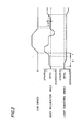
- FIG.5 is a side view showing a schematic constitution of such a sort of mechanisms as automatedly adjusting the optical beam axis of the head lamp.
- stroke sensors 1 and 2 are provided which are connected through a suspension arm and a link, respectively, to a front wheel and a rear wheel. An upward and downward movement of each wheel is transformed into each rotation angle of the stroke sensors 1 and 2.
- Output voltages produced corresponding to aforesaid rotation angles are applied to an e lectric c ontrol u nit (referred to as "ECU") 3.
- ECU e lectric c ontrol u nit
- the control unit 3 calculates the inclination angle of the main body in the back and forth direction from applied input data for measuring the upward and downward movements of the front and the rear wheels as well as from a distance between two axles, namely a wheelbase.
- An electric signal produced from the ECU 3 moves either upwardly or downwardly the optical beam axis of the head lamp through an actuator 4 toward a reverse direction with respect to that the main body inclines as far as aforesaid difference in inclination angle ⁇ from an initial position of the main body which is calculated by Equation (1) around a lamp supporting portion as a supporting point.
- GB 2309774 A discloses a vehicle lamp illumination direction control device comprising vehicle posture detection device, vehicle running condition detecting device, drive device to direct the lamp illumination direction and control device.
- the lamp illumination direction is changed in accordance with detected results from the posture detection device.
- US Patent No. 5,191,530 discloses method and apparatus to regulate illumination range of a motor vehicle.
- signals with respects to positions of the vehicle are measured at a front axle and a rear axle.
- Measured signals are processed and processed signals are used to recognize inclination changes of the vehicle, so that illumination range is controlled in accordance with recognized inclination changes.
- the sensing pulses for sensing the car speed are frequently delayed to be applying to an input terminal. If the main body changes in attitude during starting before the input pulses for sensing the car speed are applied, the optical beam axis adjustment cannot be performed when the car speed pulses are applied later even though the attitude of the main body has changed from the attitude during the standstill.
- the optical beam axis is subjected to the adjustment every time when the vehicle stops, the adequate lamp angle cannot be obtained because the optical beam axis varies due to road situations such as a slope of a road or waviness of the road surface even though there exists no variation in load of the vehicle.
- the optical beam axis adjustment operates even during the traveling of the vehicle, which is inconvenient to the system on the contrary.
- a positioning adjustment is necessary during equipping the stroke sensors for use in detecting the inclination angle of the main body because a precision in positioning for equipping the stroke sensors is required.
- the positioning adjustment during equipping the stroke sensors is too difficult to attain a suitable lamp angle.
- An object of the present invention is to provide an optical beam axis adjustment apparatus of a head lamp for use in vehicle which can always adjust adequately the optical beam axis of the lamp; and wherein a positioning adjustment during equipping a sensor for detecting an inclining angle of a main body of the vehicle can easily be performed.
- an optical beam axis adjustment apparatus of a head lamp for use in vehicle according to the present invention is constituted as follows:
- FIG.1 is a block diagram showing constitutions of an embodiment according to the present invention.
- numerical characters 1 and 2 stand for stroke sensors for sensing upward and downward displacements of a front wheel and a rear wheel which are shown respectively in FIG.5.
- Another numerical character 3 stands for a control unit for processing sensed signals produced from those stroke sensors 1 and 2 to apply a control signal for controlling a head lamp 5 to an actuator 4.
- the control unit 3 includes an angle detecting unit 3a for detecting an inclination angle of a main body in a back and forth direction, corresponding to the sensed signals produced from the stroke sensors 1 and 2 as well as to a distance between two axles; and also includes a traveling sensing unit 3b for sensing a traveling status and a stopping status of a vehicle, depending upon the sensed signals produced from the stroke sensors 1 and 2.
- 6 stands for writable memory media for recording adjustment data including the sensed signals produced from the stroke sensors 1 and 2 during adjustment of the optical beam axis of the head lamp 5 while 7 stands for a warning lamp (a pilot lamp) for lighting when the actuator 4 adjusts the optical beam axis of the head lamp 5.
- a warning lamp a pilot lamp
- an IG signal for exhibiting an operational status of an ignition switch, a H/L signal transferred from a H/L switch (a passing lamp switch) and car speed pulses produced from a car speed sensor are applied to the control unit 3, wherein a sensing anomaly in car speed sensor is to be informed when the applied car speed pulses do not coincide with the sensed signals of the traveling sensing unit 3b.
- the traveling sensing unit 3b is constituted to sense the traveling status of the vehicle, depending upon parameters of an amplitude, a phase and a frequency in output signals produced from the stroke sensors 1 and 2.
- the optical beam axis adjustment apparatus constituted mentioned above, no optical beam axis adjustment is performed during traveling of the vehicle while the optical beam axis adjustment of the head lamp 5 is carried out automatedly during stopping of the vehicle corresponding to the detected angle data calculated from the sensed signals, which are produced from stroke sensors 1 and 2 and averaged for a certain specified period before the adjustment.
- the system is constituted so as to readjust the optical beam axis of the head lamp 5.
- FIG.2 is a view for illustrating control operations of aforesaid control unit 3.
- the inclining angle ⁇ of the main body which are calculated from the output signals produced from the stroke sensors 1 and 2 respectively for the front wheel and the rear wheel utilizing Equation (1) are averaged first for a period of S seconds (referred to as "sec") preceding the adjustment for another period of T sec. Then, the averaged value in inclination angle ⁇ of the main body is transmitted to the actuator 4 as control data for controlling the lamp angle to adjust the optical beam axis of the head lamp 5.
- the constitutions mentioned above maintain the inclination angle of the main body as it is at stopping of the vehicle even if a body posture (body inclination angle) changes before the car speed pulses are applied.
- the periods S and T shown in FIG.2 may be decided depending upon mechanical characteristics of a suspension structure that the vehicle possesses.
- the optical beam axis of the head lamp 5 is then controlled by an average value which is averaged over the inclination angles during traveling and during stopping, respectively, if a change in inclination angle of the main body during stopping exceeds ⁇ d which is the inclination angle prior to the stopping. If the main body is herein inclined just at stopping of the vehicle, the adjustment of the optical beam axis of the head lamp 5 is controlled corresponding directly to a thereinafter variation in load balance, for instance, newly riding passengers without averaging.
- the traveling sensing unit 3b shown in FIG.1 distinguishes the traveling status from the stopping status of the vehicle, depending upon the signal outputs for sensing produced respectively from the stroke sensors 1 and 2 connected to the front wheel and the rear wheel of the vehicle.
- FIG.3 shows four actual examples of sensing output patterns produced from the front and the rear strokes.
- the control unit 3 judges that the car speed sensor falls into a failure mode etc., which terminates the control operation of the ECU 3 for controlling the optical beam axis of the lamp until a power supply is cut off.
- the output signal produced from the stroke sensors 1 and 2 during a lamp aiming operation (the lamp aiming means an initial adjustment in luminous intensity distribution of the head lamp performed in general just after being mounted on the main body of the vehicle) is recorded on the memory 6 as initial values, which are then employable for calibrating signal errors of the stroke sensors associated with the installing step of the stroke sensors in the main body.
- a timing chart for calibrating the sensors is shown in FIG.4.
- ON/OFF operations of the passing light switch repeated manually more than N times (for instance, 5 times) in an elapsing time of T sec (for instance, 10 sec) since turning on of the ignition switch renders the control unit 3 carry out the sensor calibration and simultaneously renders the warning lamp 7 light on for a certain period to confirm that the sensor calibration is carried out assuredly.
- a reset switch unshown in the drawings is additionally equipped in a drivers' box, wherein putting on of the reset switch continuously, for instance, for 2 sec after turning on of the ignition switch may carry out the sensor calibration.
- the aforesaid sensor output signals are recorded on the memory 6 which is attached to the control unit 3, wherein the recorded data are stored even when the supply power is cut off.
- the inclination angle of the main body during stopping is employable as the lamp control angle, which enables always to compensate adequately the optical beam axis of the lamp even when the judgment passed on the status whether the vehicle is traveling or stopping is delayed due to the variation in inclination angle of the main body that the starting of the vehicle would induce.
- the constitution according to the present invention that the lamp control angle is updated only when the variation in inclination angle of the main body exceeds the certain specified value during stopping of the vehicle also makes it possible to render the lamp control angle follow only the variation in loading status of the vehicle.
- judging a traveling mode of the vehicle out of the signal patterns produced from the front and rear stroke sensors 1 and 2 makes it possible to detect the failure modes in car speed sensor, which can then terminate the lamp control operation.
- the present constitution turns it easier to control the positioning during installation of the sensors for detecting the inclination angle of the main body.
- the technologies according to the present invention have effects that they can not only always adjust the optical beam axis of the head lamp adequately but also turn it easier to adjust the positioning during installation of the sensors for detecting the inclination angle of the main body.
Landscapes
- Engineering & Computer Science (AREA)
- Mechanical Engineering (AREA)
- Lighting Device Outwards From Vehicle And Optical Signal (AREA)
Claims (4)
- Vorrichtung zum Einstellen einer Achse eines optischen Strahles eines Scheinwerfers zur Verwendung in einem Fahrzeug, welche folgendes umfasst:Hubsensoren (1, 2) zum Erkennen von Aufwärts- und Abwärtsbewegungen eines Vorderrades und eines Hinterrades, dadurch gekennzeichnet, dass die Vorrichtung des weiteren umfasst:eine Winkelerfassungseinrichtung (3a) zum Ermitteln eines Neigungswinkels eines Hauptkörpers des Fahrzeuges in einer Rückwärts- und einer Vorwärtsrichtung als Reaktion auf gemessene Signale, welche von den Hubsensoren (1, 2) erzeugt wurden und in Bezug auf eine Entfernung zwischen zwei Achsen der Räder; undeinen Aktuator zum Variieren der Achse des optischen Strahles des Scheinwerfers (5) entsprechend den ermittelten Winkeldaten nach oben und nach unten;eine Fahrtmesseinheit (3b) zum Messen eines Fahrstatus und eines Anhaltestatus des Fahrzeuges als Reaktion auf die gemessenen Signale, welche von den Hubsensoren (1, 2) erzeugt wurden, wobeidie optische Strahlachse (5) während des Anhaltens des Fahrzeuges, abhängig von durchschnittlichen Winkelermittlungsdaten, eingestellt wird, welche durch die Hubsensoren (1, 2) gemessen und während einer bestimmten Zeitdauer vor der Einstellung gemittelt wurden; unddie optische Strahlachse (5) nachgestellt wird, wenn der Neigungswinkel des Hauptkörpers über einen gewissen spezifizierten Wert während des Anhaltens des Fahrzeuges hinaus variiert.
- Vorrichtung nach Anspruch 1, wobei:die Fahrtmesseinheit (3b) so gesteuert wird, um den Fahrzustand entsprechend Parametern, wie bspw. einer Amplitude, einer Phase und einer Frequenz der Ausgangssignale, zu messen, welche von den Hubsensoren (1, 2), die mit dem Vorderrad bzw. dem Hinterrad verbunden sind, erzeugt wurden.
- Vorrichtung nach Anspruch 1 und 2, wobei:eine Messanomalie im Fahrzeuggeschwindigkeitssignal als zu melden zu betrachten ist, falls ein verwendetes Fahrzeuggeschwindigkeitssignal nicht mit einem gemessenen Signal, weiches von der Fahrtmesseinheit (3b) erzeugt wurde, übereinstimmt.
- Vorrichtung nach den Ansprüchen 1 bis 3, welche ferner umfasst:Speichermedien (6) zum Aufzeichnen von Einstellungsdaten einschliesslich der gemessenen Signale, welche von den Hubsensoren (1, 2) während dem Einstellen der optischen Strahlenachse (5) erzeugt wurden.
Applications Claiming Priority (3)
| Application Number | Priority Date | Filing Date | Title |
|---|---|---|---|
| JP269885/97 | 1997-10-02 | ||
| JP26988597 | 1997-10-02 | ||
| JP26988597A JP3168414B2 (ja) | 1997-10-02 | 1997-10-02 | 車両用前照灯の光軸調整装置 |
Publications (3)
| Publication Number | Publication Date |
|---|---|
| EP0906850A2 EP0906850A2 (de) | 1999-04-07 |
| EP0906850A3 EP0906850A3 (de) | 2003-04-16 |
| EP0906850B1 true EP0906850B1 (de) | 2007-07-25 |
Family
ID=17478576
Family Applications (1)
| Application Number | Title | Priority Date | Filing Date |
|---|---|---|---|
| EP98118432A Expired - Lifetime EP0906850B1 (de) | 1997-10-02 | 1998-09-29 | Steuereinrichtung der Leuchtrichtung eines Kfz-Scheinwerfers |
Country Status (5)
| Country | Link |
|---|---|
| US (1) | US6109759A (de) |
| EP (1) | EP0906850B1 (de) |
| JP (1) | JP3168414B2 (de) |
| CA (1) | CA2247780C (de) |
| DE (1) | DE69838124T2 (de) |
Families Citing this family (26)
| Publication number | Priority date | Publication date | Assignee | Title |
|---|---|---|---|---|
| JP2000021227A (ja) * | 1998-04-27 | 2000-01-21 | Stanley Electric Co Ltd | 車両用前照灯 |
| EP1380468B1 (de) * | 1998-06-16 | 2006-05-17 | Denso Corporation | System zur automatischen Steuerung der Richtung der optischen Achse eines Fahrzeugscheinwerfers |
| JP2000118293A (ja) * | 1998-10-14 | 2000-04-25 | Koito Mfg Co Ltd | 自動車用ヘッドランプのオートレベリング装置 |
| JP3782602B2 (ja) * | 1999-02-15 | 2006-06-07 | 株式会社小糸製作所 | 自動車用ヘッドランプのオートレベリング装置 |
| JP3721013B2 (ja) * | 1999-08-23 | 2005-11-30 | 株式会社小糸製作所 | 自動車用ヘッドランプのオートレベリング装置 |
| JP2001171425A (ja) | 1999-12-14 | 2001-06-26 | Koito Mfg Co Ltd | 車輌用灯具の照射方向制御装置 |
| JP3782634B2 (ja) * | 2000-01-11 | 2006-06-07 | 株式会社小糸製作所 | 自動車用ヘッドランプのオートレベリング装置 |
| JP3721052B2 (ja) * | 2000-06-15 | 2005-11-30 | 株式会社小糸製作所 | 自動車用ヘッドランプのオートレベリング装置 |
| FR2814996B1 (fr) * | 2000-10-09 | 2003-01-24 | Valeo Vision | Dispositif de correction d'assiette a cablage simplifie pour vehicule automobile |
| DE10154407A1 (de) * | 2000-11-10 | 2002-06-06 | Denso Corp | Automatische Steuerung der Achsenrichtung von Scheinwerfern für Fahrzeuge |
| JP3563028B2 (ja) | 2000-11-10 | 2004-09-08 | 株式会社デンソー | 車両用前照灯光軸方向自動調整装置 |
| EP1275555A3 (de) * | 2001-07-12 | 2006-05-31 | Mitsubishi Fuso Truck and Bus Corporation | Einrichtung zur Steuerung der optischen Achse eines Fahrzeugscheinwerfers |
| JP4114735B2 (ja) * | 2001-10-24 | 2008-07-09 | 株式会社小糸製作所 | 自動車用ヘッドランプのオートレベリング装置 |
| JP4087201B2 (ja) * | 2002-09-20 | 2008-05-21 | 株式会社小糸製作所 | 車両用前照灯装置の光軸位置設定方法 |
| JP4184159B2 (ja) | 2003-06-06 | 2008-11-19 | 三菱電機株式会社 | 車両用ヘッドライト光軸制御装置 |
| JP2005067300A (ja) * | 2003-08-21 | 2005-03-17 | Denso Corp | 車両用前照灯光軸方向自動調整装置 |
| JP4145812B2 (ja) * | 2004-02-06 | 2008-09-03 | 株式会社小糸製作所 | 自動車用ヘッドランプのオートレベリング装置 |
| EP2402212B1 (de) * | 2010-07-01 | 2014-08-06 | Koito Manufacturing Co., Ltd. | Steuervorrichtung für einen Fahrzeuglampe, Fahrzeuglampe und Verfahren zur Steuerung der Fahrzeuglampe |
| USRE49776E1 (en) | 2010-10-26 | 2024-01-02 | Koito Manufacturing Co., Ltd. | Vehicle lamp controller, vehicle lamp system, and vehicle lamp control method |
| JP5787649B2 (ja) | 2010-10-26 | 2015-09-30 | 株式会社小糸製作所 | 車両用灯具の制御装置および車両用灯具システム |
| JP5778587B2 (ja) * | 2012-01-11 | 2015-09-16 | スタンレー電気株式会社 | 車両用前照灯の光軸調整装置、車両用前照灯システム |
| JP5897909B2 (ja) * | 2012-01-11 | 2016-04-06 | スタンレー電気株式会社 | 車両用前照灯の光軸調整装置、車両用前照灯システム |
| CN105793108B (zh) | 2013-12-20 | 2018-10-26 | 金泰克斯公司 | 控制外部车灯 |
| CN106573571B (zh) * | 2014-08-04 | 2019-05-21 | 金泰克斯公司 | 利用惯性传感器的驾驶员辅助系统 |
| JP6224177B2 (ja) * | 2016-06-24 | 2017-11-01 | 株式会社小糸製作所 | 車両用灯具の制御装置 |
| JP6970013B2 (ja) * | 2017-12-27 | 2021-11-24 | 株式会社小糸製作所 | 車両用灯具の制御装置 |
Family Cites Families (5)
| Publication number | Priority date | Publication date | Assignee | Title |
|---|---|---|---|---|
| DE4311669C2 (de) * | 1993-04-08 | 2002-06-13 | Bosch Gmbh Robert | Einrichtung zum Einstellen der Leuchtweite von Scheinwerfern bei Fahrzeugen |
| US5684698A (en) * | 1994-04-15 | 1997-11-04 | Kabushiki Kaisha Toyoda Jidoshokki Seisakusho | Vehicle attitude and average height control apparatus |
| DE4437949C1 (de) * | 1994-10-24 | 1996-04-04 | Daimler Benz Ag | Leuchtweitenregelung an einem Fahrzeug |
| JP3128609B2 (ja) * | 1996-02-01 | 2001-01-29 | 株式会社小糸製作所 | 車輌用灯具の照射方向制御装置 |
| JP3128611B2 (ja) * | 1996-04-26 | 2001-01-29 | 株式会社小糸製作所 | 車輌用灯具の照射方向制御装置 |
-
1997
- 1997-10-02 JP JP26988597A patent/JP3168414B2/ja not_active Expired - Lifetime
-
1998
- 1998-09-02 US US09/145,462 patent/US6109759A/en not_active Expired - Lifetime
- 1998-09-25 CA CA002247780A patent/CA2247780C/en not_active Expired - Fee Related
- 1998-09-29 DE DE69838124T patent/DE69838124T2/de not_active Expired - Lifetime
- 1998-09-29 EP EP98118432A patent/EP0906850B1/de not_active Expired - Lifetime
Also Published As
| Publication number | Publication date |
|---|---|
| DE69838124D1 (de) | 2007-09-06 |
| CA2247780A1 (en) | 1999-04-02 |
| EP0906850A3 (de) | 2003-04-16 |
| JP3168414B2 (ja) | 2001-05-21 |
| US6109759A (en) | 2000-08-29 |
| EP0906850A2 (de) | 1999-04-07 |
| DE69838124T2 (de) | 2008-04-10 |
| CA2247780C (en) | 2002-04-23 |
| JPH11105620A (ja) | 1999-04-20 |
Similar Documents
| Publication | Publication Date | Title |
|---|---|---|
| EP0906850B1 (de) | Steuereinrichtung der Leuchtrichtung eines Kfz-Scheinwerfers | |
| KR101118432B1 (ko) | 자동차 차대의 위치를 조정하기 위한 시스템, 상기 시스템의 구동 방법 및 제어 장치 | |
| JP2767220B2 (ja) | 車両の前照灯の照明距離調整装置 | |
| US7366602B2 (en) | Roll stability control system for an automotive vehicle using an external environmental sensing system | |
| US6229263B1 (en) | Lighting-direction control unit for vehicle lamp | |
| US6233510B1 (en) | Method and system for predicting road profile | |
| EP2786347B1 (de) | Ein system für die überprüfung der einstellung ein seitenrückspiegel | |
| US20070263301A1 (en) | System and Method for Automatic Adjustment of Mirrors for a Vehicle | |
| US6302553B1 (en) | Radiating direction control unit of lighting device for vehicle use | |
| US7877884B2 (en) | Dynamic axle alignment system onboard a vehicle | |
| US20180297436A1 (en) | Look Ahead Vehicle Suspension System | |
| EP1638813A1 (de) | System und verfahren zur automatischen einstellung der spiegel eines fahrzeugs | |
| JPH11151972A (ja) | 車両ヘッドライトの照射範囲の制御装置 | |
| US20240217300A1 (en) | Sensor device | |
| GB2309773A (en) | Controlling direction of vehicle lights | |
| WO2022125976A1 (en) | Calibration and operation of vehicle object detection radar with inertial measurement unit (imu) | |
| JPH10324192A (ja) | 車両のヘッドライトの照明距離を制御するための装置 | |
| JP2000198434A (ja) | 車両の縦方向傾斜を表わす信号の供給方法、滑り制御および/または車両のヨ―速度を表わす値の制御のための制御器、および車両の照明範囲の制御のための制御装置 | |
| JPS59206213A (ja) | 自動車の基準点の走行路に対する距離を監視する装置 | |
| JP2005201661A (ja) | 自動車用傾斜検出装置 | |
| JP2021056007A (ja) | 車両特性評価システムおよび車両用風洞試験設備 | |
| KR100559413B1 (ko) | 도로 곡률 변화에 따른 레이더 각도 제어 시스템 | |
| JP2001167389A (ja) | 車両の位置検出装置 | |
| KR19990057517A (ko) | 차량용 전자제어 현가장치 | |
| CN116569066A (zh) | 具有惯性测量单元(imu)的车辆对象检测雷达的校准和操作 |
Legal Events
| Date | Code | Title | Description |
|---|---|---|---|
| PUAI | Public reference made under article 153(3) epc to a published international application that has entered the european phase |
Free format text: ORIGINAL CODE: 0009012 |
|
| AK | Designated contracting states |
Kind code of ref document: A2 Designated state(s): AT BE CH CY DE DK ES FI FR GB GR IE IT LI LU MC NL PT SE |
|
| AX | Request for extension of the european patent |
Free format text: AL;LT;LV;MK;RO;SI |
|
| PUAL | Search report despatched |
Free format text: ORIGINAL CODE: 0009013 |
|
| AK | Designated contracting states |
Designated state(s): AT BE CH CY DE DK ES FI FR GB GR IE IT LI LU MC NL PT SE |
|
| AX | Request for extension of the european patent |
Extension state: AL LT LV MK RO SI |
|
| 17P | Request for examination filed |
Effective date: 20030605 |
|
| AKX | Designation fees paid |
Designated state(s): DE FR GB |
|
| 17Q | First examination report despatched |
Effective date: 20060801 |
|
| GRAP | Despatch of communication of intention to grant a patent |
Free format text: ORIGINAL CODE: EPIDOSNIGR1 |
|
| GRAS | Grant fee paid |
Free format text: ORIGINAL CODE: EPIDOSNIGR3 |
|
| GRAA | (expected) grant |
Free format text: ORIGINAL CODE: 0009210 |
|
| AK | Designated contracting states |
Kind code of ref document: B1 Designated state(s): DE FR GB |
|
| REG | Reference to a national code |
Ref country code: GB Ref legal event code: FG4D |
|
| REF | Corresponds to: |
Ref document number: 69838124 Country of ref document: DE Date of ref document: 20070906 Kind code of ref document: P |
|
| ET | Fr: translation filed | ||
| PLBE | No opposition filed within time limit |
Free format text: ORIGINAL CODE: 0009261 |
|
| STAA | Information on the status of an ep patent application or granted ep patent |
Free format text: STATUS: NO OPPOSITION FILED WITHIN TIME LIMIT |
|
| 26N | No opposition filed |
Effective date: 20080428 |
|
| REG | Reference to a national code |
Ref country code: DE Ref legal event code: R082 Ref document number: 69838124 Country of ref document: DE Representative=s name: PATENTANWAELTE UND RECHTSANWALT WEISS, ARAT & , DE Ref country code: DE Ref legal event code: R082 Ref document number: 69838124 Country of ref document: DE Representative=s name: PATENTANWAELTE UND RECHTSANWALT DR. WEISS, ARA, DE |
|
| REG | Reference to a national code |
Ref country code: FR Ref legal event code: PLFP Year of fee payment: 19 |
|
| REG | Reference to a national code |
Ref country code: FR Ref legal event code: PLFP Year of fee payment: 20 |
|
| PGFP | Annual fee paid to national office [announced via postgrant information from national office to epo] |
Ref country code: FR Payment date: 20170810 Year of fee payment: 20 Ref country code: GB Payment date: 20170927 Year of fee payment: 20 |
|
| PGFP | Annual fee paid to national office [announced via postgrant information from national office to epo] |
Ref country code: DE Payment date: 20170927 Year of fee payment: 20 |
|
| REG | Reference to a national code |
Ref country code: DE Ref legal event code: R071 Ref document number: 69838124 Country of ref document: DE |
|
| REG | Reference to a national code |
Ref country code: GB Ref legal event code: PE20 Expiry date: 20180928 |
|
| PG25 | Lapsed in a contracting state [announced via postgrant information from national office to epo] |
Ref country code: GB Free format text: LAPSE BECAUSE OF EXPIRATION OF PROTECTION Effective date: 20180928 |