EP0905433A1 - Verfahren und Vorrichtung zum Einbringen, Positionieren und Befestigen von Bauteilen in Hohlräumen unterschiedlicher Querschnitte - Google Patents
Verfahren und Vorrichtung zum Einbringen, Positionieren und Befestigen von Bauteilen in Hohlräumen unterschiedlicher Querschnitte Download PDFInfo
- Publication number
- EP0905433A1 EP0905433A1 EP98250326A EP98250326A EP0905433A1 EP 0905433 A1 EP0905433 A1 EP 0905433A1 EP 98250326 A EP98250326 A EP 98250326A EP 98250326 A EP98250326 A EP 98250326A EP 0905433 A1 EP0905433 A1 EP 0905433A1
- Authority
- EP
- European Patent Office
- Prior art keywords
- elements
- fastening elements
- fastening
- cable
- guide
- Prior art date
- Legal status (The legal status is an assumption and is not a legal conclusion. Google has not performed a legal analysis and makes no representation as to the accuracy of the status listed.)
- Granted
Links
- 238000000034 method Methods 0.000 claims abstract description 39
- 238000007373 indentation Methods 0.000 claims description 15
- 239000000853 adhesive Substances 0.000 claims description 14
- 230000001070 adhesive effect Effects 0.000 claims description 12
- 239000000463 material Substances 0.000 claims description 10
- 150000001875 compounds Chemical class 0.000 claims description 3
- 239000000109 continuous material Substances 0.000 claims description 3
- 238000012544 monitoring process Methods 0.000 claims description 3
- 238000004382 potting Methods 0.000 claims description 3
- 238000012856 packing Methods 0.000 claims description 2
- 239000012858 resilient material Substances 0.000 claims description 2
- 230000008961 swelling Effects 0.000 claims description 2
- 238000004026 adhesive bonding Methods 0.000 claims 2
- 230000001680 brushing effect Effects 0.000 claims 2
- 230000036316 preload Effects 0.000 claims 1
- 235000014676 Phragmites communis Nutrition 0.000 abstract 6
- 238000005516 engineering process Methods 0.000 description 4
- 238000009434 installation Methods 0.000 description 4
- 230000001681 protective effect Effects 0.000 description 4
- 238000005553 drilling Methods 0.000 description 3
- 238000003825 pressing Methods 0.000 description 3
- 230000000694 effects Effects 0.000 description 2
- 239000002390 adhesive tape Substances 0.000 description 1
- 238000004891 communication Methods 0.000 description 1
- 239000004020 conductor Substances 0.000 description 1
- 238000010276 construction Methods 0.000 description 1
- 238000011109 contamination Methods 0.000 description 1
- 238000013461 design Methods 0.000 description 1
- 229910003460 diamond Inorganic materials 0.000 description 1
- 239000010432 diamond Substances 0.000 description 1
- 239000003673 groundwater Substances 0.000 description 1
- 238000003780 insertion Methods 0.000 description 1
- 230000037431 insertion Effects 0.000 description 1
- 230000014759 maintenance of location Effects 0.000 description 1
- 239000002184 metal Substances 0.000 description 1
- 239000007787 solid Substances 0.000 description 1
- 239000011343 solid material Substances 0.000 description 1
- 238000005507 spraying Methods 0.000 description 1
- 238000012549 training Methods 0.000 description 1
- XLYOFNOQVPJJNP-UHFFFAOYSA-N water Substances O XLYOFNOQVPJJNP-UHFFFAOYSA-N 0.000 description 1
Images


Classifications
-
- F—MECHANICAL ENGINEERING; LIGHTING; HEATING; WEAPONS; BLASTING
- F16—ENGINEERING ELEMENTS AND UNITS; GENERAL MEASURES FOR PRODUCING AND MAINTAINING EFFECTIVE FUNCTIONING OF MACHINES OR INSTALLATIONS; THERMAL INSULATION IN GENERAL
- F16L—PIPES; JOINTS OR FITTINGS FOR PIPES; SUPPORTS FOR PIPES, CABLES OR PROTECTIVE TUBING; MEANS FOR THERMAL INSULATION IN GENERAL
- F16L55/00—Devices or appurtenances for use in, or in connection with, pipes or pipe systems
- F16L55/16—Devices for covering leaks in pipes or hoses, e.g. hose-menders
- F16L55/162—Devices for covering leaks in pipes or hoses, e.g. hose-menders from inside the pipe
- F16L55/165—Devices for covering leaks in pipes or hoses, e.g. hose-menders from inside the pipe a pipe or flexible liner being inserted in the damaged section
- F16L55/1655—Devices for covering leaks in pipes or hoses, e.g. hose-menders from inside the pipe a pipe or flexible liner being inserted in the damaged section a pipe being formed inside the old pipe by winding strip-material
-
- G—PHYSICS
- G02—OPTICS
- G02B—OPTICAL ELEMENTS, SYSTEMS OR APPARATUS
- G02B6/00—Light guides; Structural details of arrangements comprising light guides and other optical elements, e.g. couplings
- G02B6/44—Mechanical structures for providing tensile strength and external protection for fibres, e.g. optical transmission cables
- G02B6/4439—Auxiliary devices
- G02B6/4459—Ducts; Conduits; Hollow tubes for air blown fibres
-
- G—PHYSICS
- G02—OPTICS
- G02B—OPTICAL ELEMENTS, SYSTEMS OR APPARATUS
- G02B6/00—Light guides; Structural details of arrangements comprising light guides and other optical elements, e.g. couplings
- G02B6/46—Processes or apparatus adapted for installing or repairing optical fibres or optical cables
- G02B6/48—Overhead installation
-
- G—PHYSICS
- G02—OPTICS
- G02B—OPTICAL ELEMENTS, SYSTEMS OR APPARATUS
- G02B6/00—Light guides; Structural details of arrangements comprising light guides and other optical elements, e.g. couplings
- G02B6/46—Processes or apparatus adapted for installing or repairing optical fibres or optical cables
- G02B6/50—Underground or underwater installation; Installation through tubing, conduits or ducts
- G02B6/502—Installation methods in fluid conducts, e.g. pipelines
-
- G—PHYSICS
- G02—OPTICS
- G02B—OPTICAL ELEMENTS, SYSTEMS OR APPARATUS
- G02B6/00—Light guides; Structural details of arrangements comprising light guides and other optical elements, e.g. couplings
- G02B6/46—Processes or apparatus adapted for installing or repairing optical fibres or optical cables
- G02B6/50—Underground or underwater installation; Installation through tubing, conduits or ducts
- G02B6/508—Fixation devices in ducts for drawing cables
-
- H—ELECTRICITY
- H02—GENERATION; CONVERSION OR DISTRIBUTION OF ELECTRIC POWER
- H02G—INSTALLATION OF ELECTRIC CABLES OR LINES, OR OF COMBINED OPTICAL AND ELECTRIC CABLES OR LINES
- H02G1/00—Methods or apparatus specially adapted for installing, maintaining, repairing or dismantling electric cables or lines
- H02G1/06—Methods or apparatus specially adapted for installing, maintaining, repairing or dismantling electric cables or lines for laying cables, e.g. laying apparatus on vehicle
- H02G1/08—Methods or apparatus specially adapted for installing, maintaining, repairing or dismantling electric cables or lines for laying cables, e.g. laying apparatus on vehicle through tubing or conduit, e.g. rod or draw wire for pushing or pulling
- H02G1/088—Methods or apparatus specially adapted for installing, maintaining, repairing or dismantling electric cables or lines for laying cables, e.g. laying apparatus on vehicle through tubing or conduit, e.g. rod or draw wire for pushing or pulling using pulling devices movable inside conduits
Definitions
- the invention relates to a method for introducing, positioning and fastening Components, in particular pipes, cables, rods or wires in cavities different cross-sections, for example in drainage canals in which the components are already in place or introduced using a robot and one Device for performing the method.
- GB 21 29 627 is also known, on the one hand the introduction of a cable protection duct over the entire length by means of adhesive tape with subsequent spraying on of a means for the final fastening of the cable protection duct to the surface of the cable pipe and on the other hand the fastening of the cable by means of retaining clips, which are produced by the drilling / dowel technology attached to the sewer pipe wall and protected with a metal grid over the entire length of the duct.
- the disadvantages of the method are that it cannot be used for house connections supplied from above or that drilling is used.
- EP 0 158 416 also describes the installation of a communication cable which is designed in such a way that a tube which is slotted in the upper region in the longitudinal direction is first inserted into the existing drainage channel and then a protective tube is drawn into the slot. This process is very complex and covers the entire connections and reduces the channel cross section.
- the object of the invention is a method and a device for introducing, positioning and fastening components, in particular pipes, cables, rods or wires in cavities of different cross-sections, for example in drainage channels, in which the components are already located or by means of a robot be introduced to indicate that a more economical installation of components allows without expensive opening work, and damage to the existing Drainage channels is excluded.
- the object is achieved in that a robot which is known per se in the basic functions and is provided with additional required gripping, positioning and fixing devices, which either drives itself or is pulled by a cable through the drainage channel, either without fastening elements or equipped with fasteners, is inserted into the drainage channel and the pipe or cable that is already in the drainage channel, or is inserted by the robot in the same operation, and the fasteners that have either already been drawn in with the pipe or cable, or from the magazine , which is in front of, in or behind the robot, removed or repelled, taken up in the preselected positions in the drainage channel section, brought into relation to the pipe or cable and the drainage pipe inner surface and at the same time, preferably in the Sp Type of pipe connection, and preferably to the drainage duct crest, are pressed so that the pipe or cable to the drainage pipe inner surface is braced and fixed.
- the fastening elements can be coated with a seal-like adhesive to support the adhesive effect and the possible removal of voids. If it is not possible to insert the fasten
- the fastening elements are stacked on the magazine, either in the closest packing one behind the other or one above the other or next to each other or at an angle or in combination of these bearings in the pre-tensioned or deformed state or pre-tensioned or deformed by the magazine into the drainage channel.
- the method according to the invention can also be used for components such as rods and wires.
- the device according to the invention for carrying out the method consists of a robot with a basic unit that is known per se. This is with a pressure device to hold the pipe or cable and with a gripping, positioning and Fixing device and with camera monitoring of the driving and working process and optionally with an adhesive device and optionally with one or more Magazines to hold the fasteners and one if necessary Bias relief device and if necessary when using continuous material with a cutter for cutting off this material for the fasteners or a combination of these devices.
- the gripping, positioning and fixing device consists of a pressure and guide device.
- This guide device consists of one or more guide roles or one or more guide disks or one or more guide segments or one or more guide arms equipped with tools or from a combination of these, if necessary, movable and / or displaceable Elements.
- the gripping, positioning and fixing device is designed as a receiving disc which is rotatable or rotatable and can be pivoted in all directions and is located in front of, in or behind a robot which is known per se.
- the receiving disc consists of one or more guide elements which are provided with one or more holding devices for holding the fastening element during the gripping, positioning and fixing process.
- the mounting plate is equipped with the fastening element from a magazine by a feed device.
- the mounting disc is smaller than the channel diameter and is located in front of, in or behind the robot.
- the mounting disc is moved by means of a hydraulic, pneumatic or electric drive or a combination of these drive types.
- the guide elements are designed as segments or rollers or sliding bodies or pins or as a combination of these parts.
- the guide elements When receiving deformed fasteners or fasteners to be deformed during the reception, the guide elements must be adapted to the contour of the fastener, or the contour of the fastener is adapted to the shape of the guide element.
- the fastening element is fixed by moving the guide elements in the radial direction.
- a guide element When fastening elements with locking are received, a guide element is designed such that the ends for tensioning the fastening element are moved apart during the fixing process.
- the mechanism of moving apart depends on the type of locking of the fastener. Moving apart takes place in the radial and / or axial direction by elements known per se, such as gear wheels, toothed racks, worm wheels, cylinders, linkages or cables.
- the guide elements move individually or in groups at the same time or all at the same time.
- the guide elements are designed as segments, one or more or all segments are provided with one or more recesses of different geometric shapes for receiving the indentation of the fastening element. But they can also be designed without recesses.
- the fastening element used determines whether the segments are provided with or without a recess.
- the segments are arranged perpendicular to the main axis of the receiving disc either in one plane or offset in the axial direction.
- One or more holding devices are used to secure the fastening element during or after the application to the receiving disk against rapid opening.
- the holding device consists of a clamping mechanism or a magnet or suction unit or a combination of these options.
- the holding device is integrated in the receiving disc or as a separate component.
- the separate component consists of a basket or a cap-like structure.
- the movement of the guide elements and the holding device, if these are mechanical Parts exist, is done by a hydraulic, pneumatic or electric drive or a combination of these drive types.
- the movement is started or ended by pressing one or more Switch or by presetting one or more force limiters.
- the fastening elements are designed as tensioning elements and are optionally provided with additional seal-like adhesive before the fixation. These parts are made of resilient material, which adapt to the respective cross-section of the drainage channel after tensioning.
- the fastening elements for receiving the pipes or cables consist of smooth material or material with bevelled edges or chamfered edges or are profiled to increase the permanent clamping effect and the section modulus or consist of profiles of different geometric cross-sections, such as round or rectangular profiles inside or out Solid material.
- the fasteners are either without or with indentations or integrated Provide cavity of different geometric shapes, such as diamond, v and u-shaped or semicircular. These are as closed elements or divided with overlapping ends or not all over Extent of the drainage channel reaching open elements, only over at least reaching half the circumference of the drainage channel, or as open elements provided with a locking option or designed in the form of spread rings. Due to the conical design of the indentations, the fastening elements be stacked.
- Another embodiment of the device according to the invention provides that the Fasteners in existing column of drainage pipe connections are introduced.
- the retention effect can be achieved through flexible, quick-setting, even during potting compound swelling during the setting process and / or tension against the drainage pipe material.
- the thickness of the fasteners should be kept as small as possible to prevent solids from getting caught on the fasteners after installation in the drainage channel and leading to blockages.
- the robot runs through and works using camera monitoring.
- the distance between the fasteners is determined by the stiffness of the cable and depends on the construction of the drainage channel.
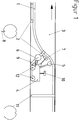
- the first exemplary embodiment shows in FIG. 1 a method in which the pipe or cable 1 with the fastening elements 2 attached to it is drawn into the drainage channel 3 before the fastening.
- the fastening elements 2 are fastened to the pipe or cable 1 at appropriate intervals in a state smaller than the inside diameter of the drainage channel.
- a robot 4 with a basic unit for final positioning of the fastening elements 2 and for fastening the pipe or cable 1, preferably in the upper region of the drainage channel 3, is then introduced into the drainage channel 3.
- the pipe or cable 1 and the fastening elements 2 lie in front of the robot 4, viewed in the direction of travel. They are pressed with the pressure roller 5, preferably against the upper region of the drainage channel 3.
- the fasteners are gripped, picked up and gripped with the gripping, positioning and fixing device 6 of the robot 4 and, if necessary, provided and positioned with seal-like adhesive from the pivotably attached adhesive device 7.
- the pretension for example held by the pin 8
- the pretension relief device 9 is released by the pretension relief device 9 and pressed by the gripping, positioning and fixing device 6 onto the inner pipe surface of the drainage channel 3.
- the gripping, positioning and fixing device 6 is designed to be rotatable and / or pivotable for carrying out changes in direction.
- the operation is monitored by a camera 10. This process is completed with the fixed fastener 11.
- the robot 4 can be adapted to different channel diameters by changing the pressure roller 5, the gripping, positioning and fixing device 6 or the driving device 12.
- the holding web can be closed, slotted or opened, and open or closed with or without a locking option.
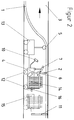
- the second exemplary embodiment shows a method in FIG Pipe or cable 1 is drawn into a drainage channel 3, but the Fastening elements only installed later. Introducing the robot that Positioning and attaching the fasteners 2 take place according to the first exemplary embodiment, however, the fastening elements 2 are prestressed in a magazine 13 in front of the robot 4 or in a magazine 14 in the robot or in a magazine 15 behind the robot. If necessary, they are removed with Support by a feed device 16.
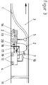
- the third exemplary embodiment shows in FIG. 3 a method in which the pipe or cable 1 is also drawn into the drainage channel 3 and the robot 4 is inserted according to the first exemplary embodiment, but the fastening elements 2 are not preloaded in the magazine compared to the second exemplary embodiment.
- the fastening elements 2 are removed from the magazine 13 with the gripping device 17 of the robot 4 and optionally with the support of a feed unit 16.
- the fasteners 2 are pretensioned by gripping the beginning of the fasteners 2 with the guide pliers 18 and at the same time advancing and, if appropriate, rotating movement or pivoting movement or rotating and pivoting movement transversely to the channel axis of the drainage channel 3 until the end of the fastening element 2 with the guide pliers 19 is gripped.
- the material that is in the magazine 13, 14 or 15, or is tracked during the entire working and driving process of the robot 4 is cut to length using the cutting device 20 in accordance with the channel cross section.
- the fastening elements can also be provided with seal-like adhesive from the adhesive device 7 working in all directions of movement.
- the positioning and fixing is carried out by pressing the fastening elements 2 with the guide pliers 18 and 19 against the inner surface of the drainage channel 3. This in turn creates a tight fit between the pipe and cable 1 and the inner surface of the drainage channel 3.
- the feed device 17 and the guide pliers 18 and 19 are designed to carry out changes in direction.
- the work process is also monitored by a camera 10 and is completed with the fixed fastening element 11.
- the robot 4 can be adapted to different drainage channel diameters by changing the pressure roller 5, the guide tongs 18 and 19 or the driving device 12.
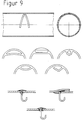
- the entire fasteners come in 5 to 9 are shown for use, the ones shown in FIG Fasteners with a cavity and a closed bridge are not used can.
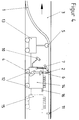
- the fourth exemplary embodiment shows in FIG. 4 a method in which the fastening elements 2 are glued on.
- the pipe or cable 1 and the robot 4 are introduced into the drainage channel 3 analogously to the second exemplary embodiment, but the fastening elements 2 lie loosely in the magazine 13, 14 or 15.
- the fastening elements 2 are attached to the gripping, positioning and fixing device 6 of the robot 4, possibly with the support of a feed device 16, and provided and positioned with a quick-adhesive agent from the adhesive device 7 working in all directions of movement.
- the fixation takes place by pressing the fastening elements 2 with the gripping, positioning and fixing device 6 against the inner pipe surface of the drainage duct 3. This creates a non-positive connection between the pipe and cable 1 and the inner pipe surface of the drainage duct 3.
- the further method steps correspond to the second embodiment.
- the robot is adapted to different drainage channel cross sections according to the first embodiment.
- the fastening elements according to FIG. 6 and according to FIG. 9 are used for this exemplary embodiment, with the exception of those which are designed with a closed cavity and as closed elements.
- the fifth exemplary embodiment shows the gripping, positioning and fixing device in FIG 6, which is arranged in the channel axis and rotatably mounted Receiving disc 21, which in turn extends in the radial direction to the channel wall moving guide elements, which are designed as segments 22 and 23.
- the segment 22 has a recess for receiving the indentation of the Fastener 2 provided.
- Holding devices 24 are attached to the segments 23, which clamp the fastening element 2 after the gripping process and secure it during the positioning and fixing process.
- the fastening element 2 is pushed in the pretensioned state by a magazine 13, 14 or 15 mounted in front of, behind or in the robot 4 known per se by the gripping device onto the receiving disc 21 and held with the holding devices 24 in such a way that the fastening element 2 snaps open during the movement of the segments 22 and 23 does not occur.
- the inclusion of the cable 1 is achieved in the radial direction by the movement of the segment 22, in which the indentation of the fastening element 2 is located.
- the positioning of the cable 1 takes place by rotating the receiving disk 21 in the circumferential direction.
- the fastening element 2 is finally fixed by moving the segments 23 in the radial direction.
- the holding devices 24 automatically release the fastening element 2 at the end of the fixing process.
- the movements of the receiving disc 21, the segments 22 and 23 and the holding devices 24 are carried out by hydraulic, pneumatic or electrical drive.
- the sixth exemplary embodiment shows in FIG. 11 the gripping, positioning and fixing device 6, which consists of a receiving disk 21 which is arranged in the channel axis so as to be rotatable and pivotable, which in turn consists of guide elements which move in the radial direction and are designed as segments 22 and 23, consists.
- the segment 22 is provided with a recess for receiving the indentation of the fastening element 2.
- Holding devices 24 are attached to the segments 23 and hold the fastening element 2 during the gripping, positioning and fixing process.
- the fastening element 2 is pushed in the non-prestressed state by a magazine 13, 14 or 15 mounted in front of, behind or in the robot known per se through the gripping device onto the receiving disk 21.
- the fastening element 2 is received on the segments 22 and 23.
- the holding devices 24 fastened to the segments 23 are pushed individually over the fastening element 2 depending on the path, so that the fastening element 2 snaps open during the movement of segments 22 and 23 is omitted.
- the inclined receiving disk 21, with the fastening element 2 located thereon, is brought into the assembly position perpendicular to the channel axis.
- the further training corresponds to the fifth embodiment.
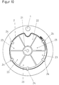
- the seventh exemplary embodiment shows in FIG. 12 the gripping, positioning and fixing device 6, which consists of a rotatably mounted receiving disc 21 arranged in the channel axis and the guide elements, which are designed as segments 22, 23 and 25 and move in the radial direction to the channel wall , consists.
- the segment 22 is provided with a recess for receiving the indentation of the fastening element 2.
- the segment 25 is provided with a sliding device 26 for tensioning the fastening element 2 by moving the ends of the fastening element 2 apart.
- Holding devices 24 are attached to the segments 22, 23 and 25 and hold the fastening element 2 during the positioning and fixing process.
- the fastening element 2 is pushed in the pretensioned state by a magazine 13, 14 or 15 mounted in front, behind or in the robot 4 known per se through the gripping device onto the receiving disk 21.
- the inclusion of the cable 1 is achieved by the movement of the receiving disc 21 in the radial direction.
- the cable 1 is positioned by rotating and moving the receiving disk 21.
- the fastening element 2 is finally fixed by actuating the sliding device 26 attached to the segment 25 to move the ends of the fastening element 2 apart.
- the holding devices 24 automatically release the fastening element 2 at the end of the fixing process.
- the movements of the receiving disc 21, the segments 22, 23 and 25, the holding devices 24 and the sliding device 26 are carried out by hydraulic, pneumatic or electric drive.
Abstract
Description
Die in der Telekommunikation weit verbreiteten Leiternetze werden bisher überwiegend in Schutzrohre im öffentlichen Straßenland gelegt. Dieses erfordert ein Verlegen dieser Schutzrohre in die Erde mit den daraus resultierenden hohen Kosten und zusätzlich der Beeinträchtigung von Umwelt und Verkehr.
Aufgrund der Zunahme der Anwendungen in der Telekommunikation müssen künftig kostengünstigere und wirtschaftlichere Wege gegangen werden. Einer davon ist die Verlegung der für die Telekommunikation erforderlichen Kabel oder der dafür benötigten Schutzrohre in diesen Kanälen (DE 42 03 718).
Der Vorteil liegt zudem darin, daß Anschlüsse ohne aufwendige Aufbrucharbeiten an das Telekommunikationsnetz hergestellt werden können.
Problematisch ist dabei das Einbringen und Befestigen der Kabel, insbesondere bei Kanälen kleiner Querschnitte.
Bekannt ist auch die GB 21 29 627, die einerseits die Einbringung eines Kabelschutzkanals über die gesamte Länge mittels Haftband mit anschließendem Aufspritzen eines Mittels zur endgültigen Befestigung des Kabelschutzkanals an der Kabelrohroberfläche und andererseits die Befestigung des Kabels mittels Halteclips, die durch die Bohr-/Dübeltechnik an die Kanalrohrwand angebracht und mit einem Metallgitter über die gesamte Länge des Kanals geschützt sind, beschreibt.
Die Nachteile des Verfahrens liegen darin, daß es nicht bei von oben zugeführten Hausanschlüssen zur Anwendung kommen kann oder das Bohren zur Anwendung kommt.
In der EP 0 158 416 wird auch die Installation eines Kommunikationskabels beschrieben, die derart gestaltet wird, daß zunächst in den vorhandenen Entwässerungskanal ein im oberen Bereich in Längsrichtung geschlitztes Rohr eingebracht und anschliessend in den Schlitz ein Schutzrohr eingezogen wird. Dieses Verfahren ist sehr aufwendig und verdeckt die gesamten Anschlüsse und verringert den Kanalquerschnitt.
Die Befestigungselemente können zur Unterstützung der Haftungswirkung und der eventuellen Hohlraumbeseitigung mit einem dichtungsähnlichen Klebstoff bestrichen werden. Ist ein Einbringen des Befestigungselementes als Spannelement nicht möglich, erfolgt die Fixierung des Befestigungselementes durch Kleben oder Vergußmasse.
Das erfindungsgemäße Verfahren kann auch bei Bauteilen, wie beispielsweise bei Stangen und Drähten eingesetzt werden.
Die Aufnahmescheibe ist kleiner als der Kanaldurchmesser und befindet sich vor, in oder hinter dem Roboter.
Die Bewegung der Aufnahmescheibe erfolgt mittels hydraulischem oder pneumatischem oder elektrischem Antrieb oder aus einer Kombination dieser Antriebsarten. Die Führungselemente sind als Segmente oder Rollen oder Gleitkörper oder Stifte oder als eine Kombination dieser Teile ausgebildet.
Bei der Aufnahme von verformten oder von während der Aufnahme zu verformenden Befestigungselementen müssen die Führungselemente der Kontur des Befestigungselementes angepaßt sein, oder die Kontur des Befestigungselementes wird der Form des Führungselementes angepaßt. Der Fixiervorgang des Befestigungselementes erfolgt durch Bewegung der Führungselemente in radialer Richtung.
Bei der Aufnahme von Befestigungselementen mit Verriegelung ist ein Führungselement derart ausgebildet, daß die Enden zum Spannen des Befestigungselementes beim Fixiervorgang auseinanderbewegt werden. Der Mechanismus des Auseinanderbewegens ist abhängig von der Art der Verriegelung des Befestigungselementes. Das Auseinanderbewegen erfolgt durch an sich bekannte Elemente wie Zahnräder, Zahnstangen, Schneckenräder, Zylinder, Gestänge oder Seile in radialer und/oder axialer Richtung.
Die Führungselemente bewegen sich einzeln oder zu mehreren gleichzeitig oder alle gleichzeitig.
Bei der Ausbildung der Führungselemente als Segmente sind ein oder mehrere oder alle Segmente mit einer oder mehreren Aussparungen unterschiedlicher geometrischer Formen für die Aufnahme der Einbuchtung des Befestigungselementes versehen. Sie können aber auch ohne Aussparungen ausgebildet sein. Ob die Segmente mit oder ohne Aussparung versehen sind, wird durch das verwendete Befestigungselement vorgegeben.
Die Segmente sind senkrecht zur Hauptachse der Aufnahmescheibe entweder in einer Ebene oder versetzt in axialer Richtung angeordnet.
Zur Sicherung des Befestigungselementes während oder nach dem Aufbringen auf die Aufnahmescheibe gegen das Aufschnellen werden eine oder mehrere Haltevorrichtungen genutzt.
Die Haltevorrichtung besteht aus einem Klemmechanismus oder einer Magnet- oder Ansaugeinheit oder aus einer Kombination dieser Möglichkeiten. Die Haltevorrichtung ist integriert in die Aufnahmescheibe oder als separates Bauteil ausgebildet. Das separate Bauteil besteht aus einem Korb oder aus einem kappenähnlichen Gebilde.
Die Befestigungselemente zur Aufnahme der Rohre oder Kabel bestehen aus glattem Material oder aus Material mit abgekanteten Rändern oder angefasten Kanten oder sind zur Erhöhung der dauerhaften Spannwirkung und des Widerstandsmomentes profiliert oder bestehen aus Profilen unterschiedlicher geometrischer Querschnitte, wie beispielsweise Rund- oder Rechteckprofil innen hohl oder aus Vollwerkstoff.
Der Abstand der Befestigungselemente ist durch die Steifigkeit des Kabels vorgegeben und ist abhängig von der Konstruktion des Entwässerungskanals.
Obwohl es zweckmäßig ist, die zu bestückenden Entwässerungskanäle vorher zu reinigen, kann das erfindungsgemäße Verfahren und die zugehörige Vorrichtung auch bei in Betrieb befindlichen Entwässerungskanälen ausgeführt werden.
Die Befestigungselemente 2 sind in einem Zustand, kleiner als der Entwässerungskanalinnendurchmesser, in entsprechenden Abständen am Rohr oder Kabel 1 befestigt. Danach wird ein Roboter 4 mit Grundeinheit zur endgültigen Positionierung der Befestigungselemente 2 und zur Befestigung des Rohres oder Kabels 1, vorzugsweise im oberen Bereich des Entwässerungskanals 3, in den Entwässerungskanal 3 eingebracht. Das Rohr oder Kabel 1 und die Befestigungselemente 2 liegen in Fahrtrichtung gesehen vor dem Roboter 4. Sie werden mit der Andruckrolle 5, vorzugsweise gegen den oberen Bereich des Entwässerungskanals 3 gedrückt. Danach werden die Befestigungselemente mit der Greif-, Positionier- und Fixiereinrichtung 6 des Roboters 4 gefaßt, aufgenommen und gegebenenfalls aus der schwenkbar angebrachten Klebeeinrichtung 7 mit dichtungsähnlichem Klebstoff versehen und positioniert. Danach wird die Vorspannung, beispielsweise gehalten durch den Stift 8, durch die Vorspannungsentlastungseinrichtung 9 gelöst und durch die Greif-, Positionier- und Fixiereinrichtung 6 an die Rohrinnenfläche des Entwässerungskanals 3 angedrückt. Dadurch entsteht ein fester Sitz zwischen Rohr oder Kabel 1 und Rohrinnenfläche des Entwässerungskanals 3. Die Greif-, Positionier- und Fixiereinrichtung 6 ist zur Durchführung von Richtungsänderungen dreh- und/oder schwenkbar gestaltet. Der Arbeitsvorgang wird von einer Kamera 10 überwacht. Dieser Vorgang ist mit dem fixierten Befestigungselement 11 abgeschlossen.
Der Roboter 4 kann durch Veränderungen der Andruckrolle 5, der Greif-, Positionier- und Fixiereinrichtung 6 oder der Fahreinrichtung 12 an unterschiedliche Kanaldurchmesser angepaßt werden.
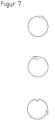
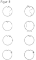
Für dieses Ausführungsbeispiel kommen die Befestigungselemente nach Figur 5, die als geschlossene Elemente mit oder ohne Einbuchtungen durch Verformung vorgespannt sind, nach Figur 6, die als offene Befestigungselemente mit oder ohne Einbuchtungen, die in vorgespanntem Zustand in den Entwässerungskanal eingebracht werden, nach Figur 7, die als offene Elemente mit überlappenden Enden mit oder ohne Einbuchtung ausgebildet sind und die in vorgespanntem Zustand in den Entwässerungskanal eingebracht werden, nach Figur 8, die als offene Elemente mit Verriegelungsmöglichkeit mit oder ohne Einbuchtung durch Verformung oder überlappenden Enden, die in vorgespanntem Zustand in den Entwässerungskanal eingebracht werden, und einige Elemente nach Figur 9, die anstelle der Einbuchtung mit einem Hohlraum, dessen Haltesteg geschlossen, geschlitzt oder geöffnet sein kann, versehen sind, und offen oder geschlossen mit oder ohne Verriegelungsmöglichkeit ausgestaltet sind, zur Anwendung.
Die Befestigungselemente können ebenfalls aus der in allen Bewegungsrichtungen arbeitenden Klebeeinrichtung 7 mit dichtungsähnlichem Klebstoff versehen werden. Die Positionierung und Fixierung erfolgt durch Andrücken der Befestigungselemente 2 mit den Führungszangen 18 und 19 an die Innenfläche des Entwässerungskanals 3. Dadurch entsteht wiederum ein fester Sitz zwischen Rohr und Kabel 1 und Innenfläche des Entwässerungskanals 3. Die Vorschubeinrichtung 17 und die Führungszangen 18 und 19 sind zur Durchführung von Richtungsänderungen beweglich gestaltet. Der Arbeitsvorgang wird ebenfalls von einer Kamera 10 überwacht und ist mit dem fixierten Befestigungselement 11 abgeschlossen.
Der Roboter 4 kann durch Veränderungen der Andruckrolle 5, der Führungszangen 18 und 19 oder der Fahreinrichtung 12 an unterschiedliche Entwässerungskanaldurchmesser angepaßt werden.
Die weiteren Verfahrensschritte entsprechen dem zweiten Ausführungsbeispiel. Die Anpassung des Roboters an unterschiedliche Entwässerungskanalquerschnitte erfolgt nach dem ersten Ausführungsbeispiel. Für dieses Ausführungsbeispiel kommen die Befestigungselemente nach Figur 6 und nach Figur 9, ausgenommen die, die mit geschlossenem Hohlraum und als geschlossene Elemente ausgebildet sind, zur Anwendung.
Das Befestigungselement 2 wird in vorgespanntem Zustand von einem vor, hinter oder in dem an sich bekannten Roboter 4 angebrachten Magazin 13, 14 oder 15 durch die Greifeinrichtung auf die Aufnahmescheibe 21 geschoben und mit den Haltevorrichtungen 24 so festgehalten, daß ein Aufschnellen des Befestigungselementes 2 während der Bewegung der Segmente 22 und 23 unterbleibt.
Die Aufnahme des Kabels 1 wird durch die Bewegung des Segmentes 22, in dem sich die Einbuchtung des Befestigungselementes 2 befindet, in radialer Richtung erreicht. Die Positionierung des Kabels 1 erfolgt durch Drehen der Aufnahmescheibe 21 in Umfangsrichtung.
Die endgültige Fixierung des Befestigungselementes 2 erfolgt durch Bewegung der Segmente 23 in radialer Richtung.
Die Haltevorrichtungen 24 geben automatisch zum Ende des Fixiervorganges das Befestigungselement 2 wieder frei.
Die Bewegungen der Aufnahmescheibe 21, der Segmente 22 und 23 und der Haltevorrichtungen 24 erfolgen durch hydraulischen, pneumatischen oder elektrischen Antrieb.
Das Segment 22 ist mit einer Aussparung für die Aufnahme der Einbuchtung des Befestigungselementes 2 versehen.
An den Segmenten 23 sind Haltevorrichtungen 24 angebracht, die das Befestigungselement 2 während des Greif-, Positionier- und Fixiervorganges festhalten.
Das Befestigungselement 2 wird in nicht vorgespanntem Zustand von einem vor, hinter oder in dem an sich bekannten Roboter angebrachten Magazin 13, 14 oder 15 durch die Greifeinrichtung auf die Aufnahmescheibe 21 geschoben.
Die geneigte Aufnahmescheibe 21, mit dem sich darauf befindenden Befestigungselement 2, wird in die Montageposition senkrecht zur Kanalachse gebracht. Die weitere Ausbildung entspricht dem fünften Ausführungsbeispiel.
Das Segment 22 ist mit einer Aussparung für die Aufnahme der Einbuchtung des Befestigungselementes 2 versehen. Das Segment 25 ist mit einer Schiebevorrichtung 26 zum Spannen des Befestigungselementes 2 durch Auseinanderbewegen der Enden des Befestigungselementes 2 versehen.
An den Segmenten 22, 23 und 25 sind Haltevorrichtungen 24 angebracht, die das Befestigungselement 2 während des Positionier- und Fixiervorgangs festhalten.
Das Befestigungselement 2 wird in vorgespanntem Zustand von einem vor, hinter oder in dem an sich bekannten Roboter 4 angebrachten Magazin 13, 14 oder 15 durch die Greifeinrichtung auf die Aufnahmescheibe 21 geschoben.
Die Aufnahme des Kabels 1 wird durch die Bewegung der Aufnahmescheibe 21 in radialer Richtung erreicht. Die Positionierung des Kabels 1 erfolgt durch Drehen und Bewegen der Aufnahmescheibe 21.
Die endgültige Fixierung des Befestigungselementes 2 erfolgt durch Betätigung der am Segment 25 angebrachten Schiebevorrichtung 26 zum Auseinanderbewegen der Enden des Befestigungselementes 2.
Die Haltevorrichtungen 24 geben automatisch zum Ende des Fixiervorganges das Befestigungselement 2 wieder frei.
Claims (30)
- Verfahren zum Einbringen, Positionieren und Befestigen von Bauteilen, insbesondere von Rohren, Kabeln, Stangen oder Drähten in Hohlräumen unterschiedlicher Querschnitte, beispielsweise in Entwässerungskanälen, mittels eines Roboters, der mit den erforderlichen Greif-, Positionier- und Fixiereinrichtungen versehen ist, und entweder selbst fährt oder per Seilzug durch den Kanal gezogen wird,
dadurch gekennzeichnet, daßder Roboter (4), entweder ohne oder mit Befestigungselementen (2) bestückt wird, in den Entwässerungskanal (3) eingefahren und das Rohr oder Kabel (1) positioniert wird, und die Befestigungselemente (2) von dem Rohr oder Kabel (1) oder von einem Magazin (13) oder (14) oder (15) in den vorgewählten Positionen in der Kanalstrecke aufgenommen werden, in Relation zum Rohr oder Kabel (1) gebracht und gleichzeitig zum Kanalscheitel hin angedrückt werden. - Verfahren nach dem Anspruch 1,
dadurch gekennzeichnet, daßdas Rohr oder Kabel (1) bereits im Entwässerungskanal liegt oder vom Roboter (4) im gleichen Arbeitsvorgang verlegt wird. - Verfahren nach den Ansprüchen 1 und 2,
dadurch gekennzeichnet, daßdie Befestigungselemente (2), die entweder bereits mit dem Rohr oder Kabel (1) in den Entwässerungskanal (3) eingezogen wurden, aufgenommen oder von dem Magazin (13) oder (14) oder (15), das vor, in oder hinter dem Roboter (4) angeordnet ist, entnommen oder abgestoßen werden. - Verfahren nach den Ansprüchen 1 bis 3,
dadurch gekennzeichnet, daßdie Befestigungselemente (2) im Entwässerungskanal (3) durch Spannen oder durch Spannen und Kleben, durch Bestreichen der der Kanalrohrfläche des Entwässerungskanals (3) zugewandten Seite der Befestigungselemente (2) vor der Fixierung mit einem dichtungsähnlichen Klebstoff oder nur durch Kleben, durch Bestreichen dieser Oberfläche mit einem schnell klebenden Mittel, fixiert werden. - Verfahren nach den Ansprüchen 1 bis 4,
dadurch gekennzeichnet, daßdie Befestigungselemente (2) auf dem Magazin (13) oder (14) oder (15) in gestapelter Form, entweder in dichtester Packung hintereinander oder übereinander oder nebeneinander oder schräg versetzt oder in Kombination, in vorgespanntem oder verformtem Zustand oder durch das Magazin (13) oder (14) oder (15) vorgespannt oder verformt, oder das sich als Endlosmaterial innerhalb oder außerhalb des Magazins (13) oder (14) oder (15) befindet, in den Entwässerungskanal (3) eingebracht werden. - Verfahren nach den Ansprüchen 1 bis 5,
dadurch gekennzeichnet, daßdie Befestigungselemente (2) vorzugsweise in Spalten der Kanalrohrverbindung fixiert werden. - Verfahren nach den Ansprüchen 1 bis 6,
dadurch gekennzeichnet, daßals Bauteile auch Stangen und Drähte eingesetzt werden. - Vorrichtung zur Durchführung des Verfahrens nach den Ansprüchen 1 bis 7,
dadurch gekennzeichnet, daßein an sich bekannter Roboter (4) mit Grundeinheit mit einer Andruckeinrichtung (5) zur Aufnahme des Rohres oder Kabels (1) und mit einer Greif-, Positionier- und Fixiereinrichtung (6) und gegebenenfalls mit einer Klebeeinrichtung (7) und mit Kameraüberwachung (10) des Fahr- und Arbeitsvorganges und gegebenenfalls mit einem oder mehreren Magazinen (13) oder (14) oder (15) zur Aufnahme der Befestigungselemente (2) und gegebenenfalls mit einer Vorspannentlastungseinrichtung (9) und bei Verwendung von Endlosmaterial mit einer Schneideinrichtung (20) für das Abschneiden des Materials für die Befestigungselemente versehen ist. - Vorrichtung nach dem Anspruch 8,
dadurch gekennzeichnet, daßdie Greif-, Positionier- und Fixiereinrichtung (6) aus einer Andruck- und/oder Führungseinrichtung besteht. - Vorrichtung nach den Ansprüchen 8 und 9,
dadurch gekennzeichnet, daßdie Führungseinrichtung aus einer oder mehreren Führungsrollen (17) oder einer oder mehreren Führungsscheiben oder einer oder mehreren Führungssegementen oder einem oder mehreren mit Werkzeug bestückten Führungsarmen (18) und (19) oder aus Kombination dieser gegebenenfalls beweglichen und/oder verschiebbaren Elementen besteht. - Vorrichtung nach den Ansprüchen 8 bis 10,
dadurch gekennzeichnet, daßdie Vorrichtung als eine drehbar oder drehbar und in allen Richtungen schwenkbare Aufnahmescheibe (21) zur Aufnahme eines Befestigungselementes (2), die aus einem oder mehreren Führungselementen, die mit einer oder mehreren Haltevorrichtungen (24) zum Halten des Befestigungselementes (2) während des Greif-, Positionier- und Fixiervorganges versehen sind, ausgebildet ist. - Vorrichtung nach den Ansprüchen 8 bis 11,
dadurch gekennzeichnet, daßdie Aufnahmescheibe (21) kleiner als der Kanaldurchmesser ist und sich vor, in oder hinter einem an sich bekannten Roboter (4) befindet, und die Bewegung der Aufnahmescheibe (21), der Führungselemente und der Haltevorrichtung (24) mittels hydraulischem, pneumatischem oder elektrischem Antrieb, oder aus einer Kombination dieser Antriebsarten, erfolgt. - Vorrichtung nach den Ansprüchen 8 bis 12,
dadurch gekennzeichnet, daßdie Führungselemente als Segmente (22), (23), oder (25) oder Rollen oder Gleitkörper oder Stifte, oder aus Kombination dieser Teile, ausgebildet sind. - Vorrichtung nach den Ansprüchen 8 bis 13,
dadurch gekennzeichnet, daßdie Führungselemente der Kontur der Befestigungselemente (2) oder umgekehrt angepaßt sind. - Vorrichtung nach den Ansprüchen 8 bis 14,
dadurch gekennzeichnet, daßdie Bewegung der Führungselemente in radialer und/oder axialer Richtung erfolgt. - Vorrichtung nach den Ansprüchen 8 bis 15,
dadurch gekennzeichnet, daßein oder mehrere Segmente (25) mit einem Mechanismus zum Auseinanderbewegen der Enden zum Spannen des Befestigungselementes (2) versehen ist. - Vorrichtung nach den Ansprüchen 8 bis 16,
dadurch gekennzeichnet, daßdie Führungselemente mit einer oder mehreren Aussparungen unterschiedlicher geometrischer Formen zur Aufnahme der Einbuchtung des Befestigungselementes (2) oder ohne Aussparung versehen und senkrecht zur Hauptachse der Aufnahmescheibe (21) entweder in einer Ebene oder versetzt in axialer Richtung angeordnet sind. - Vorrichtung nach den Ansprüchen 8 bis 17,
dadurch gekennzeichnet, daßdie Haltevorrichtung (24) aus einem Klemmechanismus oder einer Magnet- oder Ansaugeinheit besteht oder aus einer Kombination dieser Möglichkeiten. - Vorrichtung nach den Ansprüchen 8 bis 18,
dadurch gekennzeichnet, daßdie Haltevorrichtung (24) in die Aufnahmescheibe (21) integriert oder als separates Bauteil, beispielsweise als ein Korb oder ein kappenähnliches Gebilde, ausgebildet ist. - Vorrichtung nach den Ansprüchen 8 bis 19,
dadurch gekennzeichnet, daßdie Bewegung der Führungselemente einzeln, zu mehreren gleichzeitig oder aller gleichzeitig erfolgt. - Vorrichtung nach den Ansprüchen 8 bis 20,
dadurch gekennzeichnet, daßder Beginn und das Ende der Bewegungen der Aufnahmescheibe (21), der Führungselemente und der Haltevorrichtung (24) durch Betätigen eines oder mehrerer Schalter oder durch Voreinstellung eines oder mehrerer Kraftbegrenzer erfolgt. - Vorrichtung nach den Ansprüchen 8 bis 21,
dadurch gekennzeichnet, daßdie Befestigungselemente (2) Spannelemente sind, die aus federndem Material bestehen und dem Querschnitt des Entwässerungskanals (3) angepaßt sind und werden. - Vorrichtung nach den Ansprüchen 8 bis 22,
dadurch gekennzeichnet, daßdie Befestigungselemente (2) bei Nichtausbildung als Spannelement vor der Fixierung mit zusätzlich aufgebrachtem schnell klebenden Mittel versehen sind. - Vorrichtung nach den Ansprüchen 8 bis 23,
dadurch gekennzeichnet, daßdie Befestigungselemente (2) aus glattem Material oder Material mit abgekanteten Rändern und/oder angefasten Kanten oder aus Profilen unterschiedlicher geometrischer Querschnitte bestehen. - Vorrichtung nach den Ansprüchen 8 bis 24,
dadurch gekennzeichnet, daßdie Befestigungselemente (2) ohne oder mit Einbuchtungen unterschiedlicher geometrischer Formen, nach oben oder unten offen, oder mit integrierten geschlossenen oder geschlitzten Hohlräumen unterschiedlicher geometrischer Formen versehen sind. - Vorrichtung nach den Ansprüchen 8 bis 25,
dadurch gekennzeichnet, daßdie Befestigungselemente (2) als geschlossene Elemente oder geteilt mit überlappender Anordnung der Enden oder nicht über den gesamten Umfang des Entwässerungskanals (3) reichende offene Elemente ausgebildet sind. - Vorrichtung nach den Ansprüchen 8 bis 26,
dadurch gekennzeichnet, daßdie offenen Befestigungselemente (2) mit einer Verriegelungseinrichtung versehen sind. - Vorrichtung nach den Ansprüchen 8 bis 27,
dadurch gekennzeichnet, daßdie offenen Befestigungselemente (2) in Form von gespreizten Ringen ausgebildet sind. - Vorrichtung nach den Ansprüchen 8 bis 28,
dadurch gekennzeichnet, daßdie Befestigungselemente (2) durch konische Anordnung der Einbuchtungen stapelbar sind. - Vorrichtung nach den Ansprüchen 8 bis 29,
dadurch gekennzeichnet, daßdie Befestigungselemente (2) in Spalten der Kanalrohrverbindungen eingebracht und mit einer flexiblen, schnell abbindenden und/oder aufquellenden Vergußmasse verpreßt sind.
Applications Claiming Priority (4)
| Application Number | Priority Date | Filing Date | Title |
|---|---|---|---|
| DE19744006 | 1997-09-26 | ||
| DE19744006A DE19744006A1 (de) | 1997-09-26 | 1997-09-26 | Verfahren und Vorrichtung zum Einbringen, Positionieren und Befestigen von Bauteilen in Hohlräumen unterschiedlicher Querschnitte |
| DE19751415 | 1997-11-14 | ||
| DE19751415A DE19751415C2 (de) | 1997-09-26 | 1997-11-14 | Vorrichtung zum Greifen, Positionieren und Fixieren von Befestigungselementen in Hohlräumen unterschiedlicher Querschnitte |
Publications (2)
| Publication Number | Publication Date |
|---|---|
| EP0905433A1 true EP0905433A1 (de) | 1999-03-31 |
| EP0905433B1 EP0905433B1 (de) | 2002-04-17 |
Family
ID=26040603
Family Applications (1)
| Application Number | Title | Priority Date | Filing Date |
|---|---|---|---|
| EP98250326A Expired - Lifetime EP0905433B1 (de) | 1997-09-26 | 1998-09-15 | Verfahren und Vorrichtung zum Einbringen, Positionieren und Befestigen von Bauteilen in Hohlräumen unterschiedlicher Querschnitte |
Country Status (6)
| Country | Link |
|---|---|
| EP (1) | EP0905433B1 (de) |
| AT (1) | ATE216474T1 (de) |
| DE (2) | DE19751415C2 (de) |
| DK (1) | DK0905433T3 (de) |
| ES (1) | ES2172861T3 (de) |
| PT (1) | PT905433E (de) |
Cited By (10)
| Publication number | Priority date | Publication date | Assignee | Title |
|---|---|---|---|---|
| DE10148257A1 (de) * | 2001-09-30 | 2003-04-17 | Epros Umweltschutztechnik Gmbh | Verfahren zum Verlegen von mit Harz getränkten Gewebestreifen und einen Verlegeroboter zur Durchführung des Verfahrens |
| US7179019B2 (en) | 2000-08-07 | 2007-02-20 | Ashimori Industry Co., Ltd. | Method and structure for laying communication cable in underground line, and members used for laying |
| FR2893695A1 (fr) * | 2005-11-21 | 2007-05-25 | Sogetrel Sa | Installation d'elements de soutien ponctuel d'un cable dans une canalisation |
| EP1868020A1 (de) * | 2006-06-15 | 2007-12-19 | Sogetrel | Verfahren und Apparat zur Installation von Kabeln und Hüllen in nicht-begehbaren Kanalisationen |
| CN100381849C (zh) * | 2004-07-08 | 2008-04-16 | 上海交通大学 | 排水管道内通讯光缆的挂装方法 |
| NL2006062C2 (en) * | 2011-01-25 | 2012-07-30 | Jelcer Ip B V | A cable fastening element and use thereof for fastening of a cable into a tube. |
| WO2014096819A1 (en) * | 2012-12-20 | 2014-06-26 | Balfour Beatty Plc | Method and apparatus for the installation of cables or pipes in tunnels |
| CN105240644A (zh) * | 2015-07-31 | 2016-01-13 | 厦门市安越非开挖工程技术有限公司 | 一种管道裂缝修复装置和修复方法 |
| CN111856683A (zh) * | 2020-08-06 | 2020-10-30 | 南宁职业技术学院 | 一种基于通信设计的地下光缆走线装置及地下走线方法 |
| CN111856672A (zh) * | 2020-08-06 | 2020-10-30 | 南宁职业技术学院 | 一种通信工程用防干扰数据传输线及其制备方法 |
Citations (8)
| Publication number | Priority date | Publication date | Assignee | Title |
|---|---|---|---|---|
| DE1650994A1 (de) | 1967-02-27 | 1970-12-03 | Malmstroem Sven Erik | Kunststoffschelle fuer elektrische Kabel,Rohrleitungen u.dgl. |
| GB2129627A (en) | 1982-09-22 | 1984-05-16 | Water Res Centre | Installation of communications cables |
| DE3501676A1 (de) | 1984-02-11 | 1985-08-22 | Günter 5880 Lüdenscheid Mesenhöller | Schelle zur befestigung von rohren |
| EP0158415A1 (de) * | 1984-02-21 | 1985-10-16 | Water Research Centre | Installation von Fernmeldekabeln in ein Rohr |
| EP0158416A1 (de) | 1984-02-21 | 1985-10-16 | Water Research Centre | Installation von Fernmeldekabeln in ein Rohr |
| EP0251907A2 (de) | 1986-06-25 | 1988-01-07 | Nippon Hume Pipe Co., Ltd. | Vorrichtung zum Verlegen eines Kabels in einem Rohr |
| DE4203718A1 (de) | 1992-02-08 | 1993-08-12 | Ant Nachrichtentech | Lichtwellenleiter-kabelnetz und verfahren zu dessen verlegung |
| DE19701787A1 (de) * | 1997-01-20 | 1998-07-23 | Hecht Agathe | Lichtwellenleiterkabelnetz und Verfahren zum Verlegen eines Lichtwellenleiterkabelnetzes |
Family Cites Families (3)
| Publication number | Priority date | Publication date | Assignee | Title |
|---|---|---|---|---|
| WO1987004192A1 (en) * | 1986-01-13 | 1987-07-16 | Maschinenfabrik Andritz Actiengesellschaft | Device and process for treating the surface of strips with liquids |
| DE4401318C2 (de) * | 1993-09-04 | 1996-07-25 | Uhrig Kanaltechnik Gmbh | Vorrichtung zum Abdichten von Leckstellen in Rohren vom Rohrinnern her und Verfahren zum Abdichten der Leckstellen |
| DE29700912U1 (de) * | 1997-01-20 | 1997-02-27 | Hecht Martin | Lichtwellenleiterkabelnetz |
-
1997
- 1997-11-14 DE DE19751415A patent/DE19751415C2/de not_active Expired - Fee Related
-
1998
- 1998-09-15 PT PT98250326T patent/PT905433E/pt unknown
- 1998-09-15 AT AT98250326T patent/ATE216474T1/de not_active IP Right Cessation
- 1998-09-15 EP EP98250326A patent/EP0905433B1/de not_active Expired - Lifetime
- 1998-09-15 ES ES98250326T patent/ES2172861T3/es not_active Expired - Lifetime
- 1998-09-15 DE DE59803827T patent/DE59803827D1/de not_active Expired - Fee Related
- 1998-09-15 DK DK98250326T patent/DK0905433T3/da active
Patent Citations (9)
| Publication number | Priority date | Publication date | Assignee | Title |
|---|---|---|---|---|
| DE1650994A1 (de) | 1967-02-27 | 1970-12-03 | Malmstroem Sven Erik | Kunststoffschelle fuer elektrische Kabel,Rohrleitungen u.dgl. |
| GB2129627A (en) | 1982-09-22 | 1984-05-16 | Water Res Centre | Installation of communications cables |
| US4647251A (en) * | 1982-09-22 | 1987-03-03 | Cabletime (Installations) Limited | Installation of communications cables |
| DE3501676A1 (de) | 1984-02-11 | 1985-08-22 | Günter 5880 Lüdenscheid Mesenhöller | Schelle zur befestigung von rohren |
| EP0158415A1 (de) * | 1984-02-21 | 1985-10-16 | Water Research Centre | Installation von Fernmeldekabeln in ein Rohr |
| EP0158416A1 (de) | 1984-02-21 | 1985-10-16 | Water Research Centre | Installation von Fernmeldekabeln in ein Rohr |
| EP0251907A2 (de) | 1986-06-25 | 1988-01-07 | Nippon Hume Pipe Co., Ltd. | Vorrichtung zum Verlegen eines Kabels in einem Rohr |
| DE4203718A1 (de) | 1992-02-08 | 1993-08-12 | Ant Nachrichtentech | Lichtwellenleiter-kabelnetz und verfahren zu dessen verlegung |
| DE19701787A1 (de) * | 1997-01-20 | 1998-07-23 | Hecht Agathe | Lichtwellenleiterkabelnetz und Verfahren zum Verlegen eines Lichtwellenleiterkabelnetzes |
Cited By (13)
| Publication number | Priority date | Publication date | Assignee | Title |
|---|---|---|---|---|
| US7179019B2 (en) | 2000-08-07 | 2007-02-20 | Ashimori Industry Co., Ltd. | Method and structure for laying communication cable in underground line, and members used for laying |
| DE10148257A1 (de) * | 2001-09-30 | 2003-04-17 | Epros Umweltschutztechnik Gmbh | Verfahren zum Verlegen von mit Harz getränkten Gewebestreifen und einen Verlegeroboter zur Durchführung des Verfahrens |
| CN100381849C (zh) * | 2004-07-08 | 2008-04-16 | 上海交通大学 | 排水管道内通讯光缆的挂装方法 |
| FR2893695A1 (fr) * | 2005-11-21 | 2007-05-25 | Sogetrel Sa | Installation d'elements de soutien ponctuel d'un cable dans une canalisation |
| EP1868020A1 (de) * | 2006-06-15 | 2007-12-19 | Sogetrel | Verfahren und Apparat zur Installation von Kabeln und Hüllen in nicht-begehbaren Kanalisationen |
| WO2007144523A1 (fr) * | 2006-06-15 | 2007-12-21 | Sogetrel | Procede et dispositif d'installation de cables et gaines dans une canalisation non visitable |
| FR2902484A1 (fr) * | 2006-06-15 | 2007-12-21 | Sogetrel Sa | "procede d'installation de cables, gaines et analogues dans une canalisation non visitable et dispositif pour sa mise en oeuvre" |
| NL2006062C2 (en) * | 2011-01-25 | 2012-07-30 | Jelcer Ip B V | A cable fastening element and use thereof for fastening of a cable into a tube. |
| WO2014096819A1 (en) * | 2012-12-20 | 2014-06-26 | Balfour Beatty Plc | Method and apparatus for the installation of cables or pipes in tunnels |
| CN105240644A (zh) * | 2015-07-31 | 2016-01-13 | 厦门市安越非开挖工程技术有限公司 | 一种管道裂缝修复装置和修复方法 |
| CN111856683A (zh) * | 2020-08-06 | 2020-10-30 | 南宁职业技术学院 | 一种基于通信设计的地下光缆走线装置及地下走线方法 |
| CN111856672A (zh) * | 2020-08-06 | 2020-10-30 | 南宁职业技术学院 | 一种通信工程用防干扰数据传输线及其制备方法 |
| CN111856683B (zh) * | 2020-08-06 | 2023-05-02 | 南宁职业技术学院 | 一种基于通信设计的地下光缆走线装置及地下走线方法 |
Also Published As
| Publication number | Publication date |
|---|---|
| EP0905433B1 (de) | 2002-04-17 |
| DE19751415A1 (de) | 1999-06-17 |
| DE19751415C2 (de) | 2001-05-23 |
| ATE216474T1 (de) | 2002-05-15 |
| DE59803827D1 (de) | 2002-05-23 |
| ES2172861T3 (es) | 2002-10-01 |
| PT905433E (pt) | 2002-09-30 |
| DK0905433T3 (da) | 2002-07-01 |
Similar Documents
| Publication | Publication Date | Title |
|---|---|---|
| DE3640226C2 (de) | ||
| DE3413294C1 (de) | Verfahren und Vorrichtung zum Einbau von Kunststoffrohrstuecken in Abwasserrohre | |
| EP0905433B1 (de) | Verfahren und Vorrichtung zum Einbringen, Positionieren und Befestigen von Bauteilen in Hohlräumen unterschiedlicher Querschnitte | |
| DE4031949C2 (de) | Verfahren und Vorrichtung zur Sanierung von Abwasserkanälen | |
| DE4238700C2 (de) | Vorrichtung zur Befestigung von Verbindungselementen an Rohrleitungen | |
| DE19744006A1 (de) | Verfahren und Vorrichtung zum Einbringen, Positionieren und Befestigen von Bauteilen in Hohlräumen unterschiedlicher Querschnitte | |
| EP2044286B1 (de) | Vorrichtung zum verbinden eines strangabschnittes mit einem zugelement | |
| DE102015000499A1 (de) | Vortriebsroboter für Kanäle oder Leitungen | |
| EP1057231B1 (de) | Vorrichtung zum einsetzen von langgestreckten gegenständen in klammern | |
| DE19843263A1 (de) | Verfahren zum Verlegen von Verlegeobjekten in Kanälen, Vorrichtung zur Durchführung des Verfahrens sowie Mittel zur Verwendung bei dem Verfahren | |
| DE10122344C1 (de) | Kabelverlegesystem | |
| EP0681135A2 (de) | Vorrichtung zur Durchführung von Leitungen durch eine Öffnung in einer Wand | |
| DE19533949A1 (de) | Rohreinspannvorrichtung | |
| DE19861090C2 (de) | Verfahren zum Verlegen von Verlegeobjekten in Kanälen, Vorrichtung zur Durchführung des Verfahrens, Verlegeroboter zur Durchführung des Verfahrens, sowie verlegtes Verlegeobjekt | |
| DE3628326A1 (de) | Stuetz- und halteelement fuer einen gebogenen teil einer rohrleitung | |
| EP1847744A2 (de) | Vorrichtung zum Abdichten eines Rohrs | |
| DE102014115646A1 (de) | Anlage zum Verlegen von Leerrohren in Abwasserkanälen | |
| DE3832399A1 (de) | Rohrhalter und verfahren zur rohrmontage mittels eines rohrhalters | |
| DE102019126990B4 (de) | Zange zum Lösen einer Leitungsverbindung | |
| DE4022916A1 (de) | Verfahren zur abdichtung von stossfugen an verlegten rohrleitungen sowie vorrichtung und dichtungselement zur durchfuehrung des verfahrens | |
| EP1116859B1 (de) | Werkzeug zum Zusammenfügen und/oder Trennen von Rohren | |
| EP0936478A1 (de) | Vorrichtung zum Montieren einer Innenbride in einem nichtbegehbaren Rohr | |
| DE19540559A1 (de) | Leitungskupplung für Fluidleitungen | |
| EP1529624A1 (de) | Vorrichtung zum Verschweissen von thermoplastischen Rohrelementen | |
| DE19640697A1 (de) | Vorrichtung zum Transport und zur Manipulation eines Werkzeugs in einem Abwasserrohr eines Kanalnetzes |
Legal Events
| Date | Code | Title | Description |
|---|---|---|---|
| PUAI | Public reference made under article 153(3) epc to a published international application that has entered the european phase |
Free format text: ORIGINAL CODE: 0009012 |
|
| AK | Designated contracting states |
Kind code of ref document: A1 Designated state(s): AT BE CH DE DK ES FR GB GR IT LI NL PT SE |
|
| AX | Request for extension of the european patent |
Free format text: AL;LT;LV;MK;RO;SI |
|
| 17P | Request for examination filed |
Effective date: 19990304 |
|
| AKX | Designation fees paid |
Free format text: AT BE CH DE DK ES FR GB GR IT LI NL PT SE |
|
| 17Q | First examination report despatched |
Effective date: 20010426 |
|
| GRAG | Despatch of communication of intention to grant |
Free format text: ORIGINAL CODE: EPIDOS AGRA |
|
| GRAG | Despatch of communication of intention to grant |
Free format text: ORIGINAL CODE: EPIDOS AGRA |
|
| GRAH | Despatch of communication of intention to grant a patent |
Free format text: ORIGINAL CODE: EPIDOS IGRA |
|
| REG | Reference to a national code |
Ref country code: GB Ref legal event code: IF02 |
|
| GRAH | Despatch of communication of intention to grant a patent |
Free format text: ORIGINAL CODE: EPIDOS IGRA |
|
| GRAA | (expected) grant |
Free format text: ORIGINAL CODE: 0009210 |
|
| RAP1 | Party data changed (applicant data changed or rights of an application transferred) |
Owner name: BERLINER WASSERBETRIEBE ANSTALT DES OEFFENTLICHEN |
|
| RTI1 | Title (correction) |
Free format text: METHOD AND DEVICE FOR INSTALLING, POSITIONING AND FIXING OF PARTS IN CAVITIES OF DIVERGING CROSS SECTIONS |
|
| RAP1 | Party data changed (applicant data changed or rights of an application transferred) |
Owner name: BERLINER WASSERBETRIEBE ANSTALT DES OEFFENTLICHEN |
|
| AK | Designated contracting states |
Kind code of ref document: B1 Designated state(s): AT BE CH DE DK ES FR GB GR IT LI NL PT SE |
|
| PG25 | Lapsed in a contracting state [announced via postgrant information from national office to epo] |
Ref country code: GR Free format text: LAPSE BECAUSE OF FAILURE TO SUBMIT A TRANSLATION OF THE DESCRIPTION OR TO PAY THE FEE WITHIN THE PRESCRIBED TIME-LIMIT Effective date: 20020417 |
|
| REF | Corresponds to: |
Ref document number: 216474 Country of ref document: AT Date of ref document: 20020515 Kind code of ref document: T |
|
| REG | Reference to a national code |
Ref country code: CH Ref legal event code: EP |
|
| GBT | Gb: translation of ep patent filed (gb section 77(6)(a)/1977) |
Effective date: 20020417 |
|
| REG | Reference to a national code |
Ref country code: CH Ref legal event code: NV Representative=s name: ROTTMANN, ZIMMERMANN + PARTNER AG |
|
| REF | Corresponds to: |
Ref document number: 59803827 Country of ref document: DE Date of ref document: 20020523 |
|
| REG | Reference to a national code |
Ref country code: DK Ref legal event code: T3 |
|
| PGFP | Annual fee paid to national office [announced via postgrant information from national office to epo] |
Ref country code: PT Payment date: 20020716 Year of fee payment: 5 |
|
| PGFP | Annual fee paid to national office [announced via postgrant information from national office to epo] |
Ref country code: GR Payment date: 20020719 Year of fee payment: 5 |
|
| PGFP | Annual fee paid to national office [announced via postgrant information from national office to epo] |
Ref country code: BE Payment date: 20020805 Year of fee payment: 5 |
|
| PGFP | Annual fee paid to national office [announced via postgrant information from national office to epo] |
Ref country code: CH Payment date: 20020829 Year of fee payment: 5 Ref country code: AT Payment date: 20020829 Year of fee payment: 5 |
|
| REG | Reference to a national code |
Ref country code: GR Ref legal event code: EP Ref document number: 20020401154 Country of ref document: GR |
|
| PGFP | Annual fee paid to national office [announced via postgrant information from national office to epo] |
Ref country code: ES Payment date: 20020910 Year of fee payment: 5 |
|
| PGFP | Annual fee paid to national office [announced via postgrant information from national office to epo] |
Ref country code: GB Payment date: 20020913 Year of fee payment: 5 |
|
| PGFP | Annual fee paid to national office [announced via postgrant information from national office to epo] |
Ref country code: DK Payment date: 20020917 Year of fee payment: 5 Ref country code: SE Payment date: 20020917 Year of fee payment: 5 |
|
| PGFP | Annual fee paid to national office [announced via postgrant information from national office to epo] |
Ref country code: FR Payment date: 20020927 Year of fee payment: 5 |
|
| PGFP | Annual fee paid to national office [announced via postgrant information from national office to epo] |
Ref country code: NL Payment date: 20020930 Year of fee payment: 5 |
|
| REG | Reference to a national code |
Ref country code: PT Ref legal event code: SC4A Free format text: AVAILABILITY OF NATIONAL TRANSLATION Effective date: 20020716 |
|
| REG | Reference to a national code |
Ref country code: ES Ref legal event code: FG2A Ref document number: 2172861 Country of ref document: ES Kind code of ref document: T3 |
|
| ET | Fr: translation filed | ||
| PLBE | No opposition filed within time limit |
Free format text: ORIGINAL CODE: 0009261 |
|
| STAA | Information on the status of an ep patent application or granted ep patent |
Free format text: STATUS: NO OPPOSITION FILED WITHIN TIME LIMIT |
|
| 26N | No opposition filed |
Effective date: 20030120 |
|
| PG25 | Lapsed in a contracting state [announced via postgrant information from national office to epo] |
Ref country code: GB Free format text: LAPSE BECAUSE OF NON-PAYMENT OF DUE FEES Effective date: 20030915 Ref country code: AT Free format text: LAPSE BECAUSE OF NON-PAYMENT OF DUE FEES Effective date: 20030915 |
|
| PG25 | Lapsed in a contracting state [announced via postgrant information from national office to epo] |
Ref country code: SE Free format text: LAPSE BECAUSE OF NON-PAYMENT OF DUE FEES Effective date: 20030916 Ref country code: ES Free format text: LAPSE BECAUSE OF NON-PAYMENT OF DUE FEES Effective date: 20030916 |
|
| PGFP | Annual fee paid to national office [announced via postgrant information from national office to epo] |
Ref country code: DE Payment date: 20030917 Year of fee payment: 6 |
|
| PG25 | Lapsed in a contracting state [announced via postgrant information from national office to epo] |
Ref country code: LI Free format text: LAPSE BECAUSE OF NON-PAYMENT OF DUE FEES Effective date: 20030930 Ref country code: DK Free format text: LAPSE BECAUSE OF NON-PAYMENT OF DUE FEES Effective date: 20030930 Ref country code: CH Free format text: LAPSE BECAUSE OF NON-PAYMENT OF DUE FEES Effective date: 20030930 Ref country code: BE Free format text: LAPSE BECAUSE OF NON-PAYMENT OF DUE FEES Effective date: 20030930 |
|
| BERE | Be: lapsed |
Owner name: *BERLINER WASSERBETRIEBE ANSTALT DES OFFENTLICHEN Effective date: 20030930 |
|
| PG25 | Lapsed in a contracting state [announced via postgrant information from national office to epo] |
Ref country code: PT Free format text: LAPSE BECAUSE OF NON-PAYMENT OF DUE FEES Effective date: 20040331 |
|
| PG25 | Lapsed in a contracting state [announced via postgrant information from national office to epo] |
Ref country code: NL Free format text: LAPSE BECAUSE OF NON-PAYMENT OF DUE FEES Effective date: 20040401 |
|
| EUG | Se: european patent has lapsed | ||
| GBPC | Gb: european patent ceased through non-payment of renewal fee |
Effective date: 20030915 |
|
| REG | Reference to a national code |
Ref country code: DK Ref legal event code: EBP |
|
| REG | Reference to a national code |
Ref country code: CH Ref legal event code: PL |
|
| PG25 | Lapsed in a contracting state [announced via postgrant information from national office to epo] |
Ref country code: FR Free format text: LAPSE BECAUSE OF NON-PAYMENT OF DUE FEES Effective date: 20040528 |
|
| NLV4 | Nl: lapsed or anulled due to non-payment of the annual fee |
Effective date: 20040401 |
|
| REG | Reference to a national code |
Ref country code: PT Ref legal event code: MM4A Free format text: LAPSE DUE TO NON-PAYMENT OF FEES Effective date: 20040331 |
|
| REG | Reference to a national code |
Ref country code: FR Ref legal event code: ST |
|
| REG | Reference to a national code |
Ref country code: ES Ref legal event code: FD2A Effective date: 20030916 |
|
| PG25 | Lapsed in a contracting state [announced via postgrant information from national office to epo] |
Ref country code: DE Free format text: LAPSE BECAUSE OF NON-PAYMENT OF DUE FEES Effective date: 20050401 |
|
| PG25 | Lapsed in a contracting state [announced via postgrant information from national office to epo] |
Ref country code: IT Free format text: LAPSE BECAUSE OF NON-PAYMENT OF DUE FEES Effective date: 20050915 |