EP0903559A2 - Informationsaufzeichnungsapparat mit Interferenzvorrichtung zur Positionsbestimmung und Positionierung - Google Patents
Informationsaufzeichnungsapparat mit Interferenzvorrichtung zur Positionsbestimmung und Positionierung Download PDFInfo
- Publication number
- EP0903559A2 EP0903559A2 EP98117859A EP98117859A EP0903559A2 EP 0903559 A2 EP0903559 A2 EP 0903559A2 EP 98117859 A EP98117859 A EP 98117859A EP 98117859 A EP98117859 A EP 98117859A EP 0903559 A2 EP0903559 A2 EP 0903559A2
- Authority
- EP
- European Patent Office
- Prior art keywords
- light beams
- light beam
- light
- splitted
- splitting
- Prior art date
- Legal status (The legal status is an assumption and is not a legal conclusion. Google has not performed a legal analysis and makes no representation as to the accuracy of the status listed.)
- Granted
Links
Images
Classifications
-
- G—PHYSICS
- G11—INFORMATION STORAGE
- G11B—INFORMATION STORAGE BASED ON RELATIVE MOVEMENT BETWEEN RECORD CARRIER AND TRANSDUCER
- G11B5/00—Recording by magnetisation or demagnetisation of a record carrier; Reproducing by magnetic means; Record carriers therefor
- G11B5/48—Disposition or mounting of heads or head supports relative to record carriers ; arrangements of heads, e.g. for scanning the record carrier to increase the relative speed
- G11B5/58—Disposition or mounting of heads or head supports relative to record carriers ; arrangements of heads, e.g. for scanning the record carrier to increase the relative speed with provision for moving the head for the purpose of maintaining alignment of the head relative to the record carrier during transducing operation, e.g. to compensate for surface irregularities of the latter or for track following
- G11B5/596—Disposition or mounting of heads or head supports relative to record carriers ; arrangements of heads, e.g. for scanning the record carrier to increase the relative speed with provision for moving the head for the purpose of maintaining alignment of the head relative to the record carrier during transducing operation, e.g. to compensate for surface irregularities of the latter or for track following for track following on disks
- G11B5/59677—Disposition or mounting of heads or head supports relative to record carriers ; arrangements of heads, e.g. for scanning the record carrier to increase the relative speed with provision for moving the head for the purpose of maintaining alignment of the head relative to the record carrier during transducing operation, e.g. to compensate for surface irregularities of the latter or for track following for track following on disks with optical servo tracking
Definitions
- This invention relates to an interference device, a position detecting device, a positioning device and an information recording apparatus using the same.
- This invention can be applied particularly well to a position detecting device for detecting the positional fluctuation of an object in non-contact such as an interference length measuring device for an object like a hard disc drive magnetic head, a positioning device and a manufacturing apparatus for a hard disc drive device (hereinafter referred to as HDD) used in a computer utilizing the same, and above all, an apparatus for writing a servo track signal into a hard disc in the HDD.
- a position detecting device for detecting the positional fluctuation of an object in non-contact such as an interference length measuring device for an object like a hard disc drive magnetic head, a positioning device and a manufacturing apparatus for a hard disc drive device (hereinafter referred to as HDD) used in a computer utilizing the same, and above all, an apparatus for writing a servo track signal into a hard disc in the HDD.
- HDD hard disc drive device
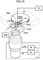
- FIG. 1A of the accompanying drawings shows an illustration of an apparatus for writing a servo track signal into a hard disc in the HDD according to the conventional art.
- HDD designates a hard disc drive device
- HD denotes hard discs
- SLID designates a slider
- ARM1 denotes a magnetic head arm
- VCM designates a voice coil motor
- OHD denotes the spindle of the hard discs HD
- O designates the rotary shaft of the magnetic head arm ARM1.
- a magnetic recording medium is deposited by evaporation on the surface of each hard disc.
- the hard discs HD are normally rotated as a unit at a high speed about the spindle OHD, and a magnetic head is disposed in proximity to the surface of each hard disc HD.
- the magnetic head is incorporated in the portion of a substantially rectangular parallelopiped called the slider SLID mounted on the tip end of each arm portion of the magnetic head arm ARM1 having the center of rotation O outside the hard discs HD, and is relatively movable substantially in a radial direction on the hard discs HD by rotatively driving the arm ARM1 by the voice coil motor VCM.
- magnetic information can be written or read at any position (track) on the surfaces of the hard discs by the rotated hard discs HD and the arcuately moved magnetic head.
- a magnetic recording system onto the surface of the hard disc is such that each hard disc is splitted into a plurality of circular ring-shaped tracks of different radii concentric with the center of rotation OHD of the hard discs, and further each of the circular ring-shaped tracks in turn is splitted into a plurality of arcs and finally, magnetic information is recorded and reproduced on the plurality of arcuate areas time-serially along the circumferential direction.
- the recording density in the radial direction is expressed by track density TPI (track/inch) per length of an inch, and at present it is of the order of 10000 TPI. This means that the track interval is about 3 ⁇ .
- TPI track density
- the important technique here is to successively write servo track signals into the hard disc while effecting positioning of high resolving power within a short time.
- PROD designates a push rod
- ARM2 denotes an arm for the push rod PROD
- MO designates a positioning control motor
- RE denotes a rotary encoder for detecting the amount of rotation of the rotary shaft of the motor MO
- SP designates a signal processor for analyzing the detection output from the rotary encoder RE, and producing a positioning command signal to the servo track signal writing-in position of the magnetic head
- MD denotes a motor driver for driving the motor MO by the command signal of the signal processor SP.
- the cylindrical surface of the push rod PROD was pushed against the side of the magnetic head arm ARM1 (the arm portion for the magnetic head for the underside of the lowermost hard disc), and the arm ARM2 was rotated to thereby sequentially finely feed and position the magnetic head arm through the push rod PROD while taking feedback control by the system of the rotary encoder RE, the signal processor SP and the motor driver MD, and servo track signals from a signal generator SG were successively written in from the magnetic head.
- some electric current was usually supplied to the voice coil motor VCM and the push rod PROD was also pushed from the head arm ARM1 side.
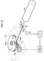
- FIG. 1B of the accompanying drawings shows an example of such an apparatus.
- HeNe designates a laser light source
- M1 and M2 denote mirrors
- BS designates a beam splitter
- CC denotes a retroreflector such as a corner cube provided on the magnetic head arm ARM1
- PD designates a light receiving element.
- the laser light source HeNe, the mirrors M1 and M2, the beam splitter BS and the retroreflector CC together constitute a Michelson type interferometer, and the interference light of light beams L1 and L2 which have passed the retroreflector CC and the mirrors M1 and M2, respectively, is detected by the light receiving element PD to thereby obtain the positional information of the magnetic head arm ARM1.
- a signal processor SP produces a command and controls an electric current flowing from a voice coil motor driver VCMD to a voice coil motor VCM to thereby directly move the magnetic head arm and provide appropriate control.
- the present invention has as an object thereof to provide a position detecting device and a positioning device capable of detecting the position of an object and position the object in non-contact at high reliability and with high accuracy and high resolving power, an interference device making the same realizable and an information recording apparatus using the same.
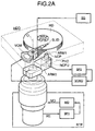
- Fig. 2A schematically shows the construction of a servo track signal writing-in apparatus according to a first embodiment of the present invention.
- members similar to those in the aforedescribed conventional art are given the same reference characters.
- a hard disc drive device HDD has mounted thereon a magnetic head arm ARM1 having a rotary shaft O outside a hard disc HD, and a slider SLID mounted on the tip end thereof is disposed with a gap of 0.5 ⁇ m (or less) in opposed relationship with the surface of the hard disc, and is arcuately moved by the rotation of the magnetic head arm ARM1.
- the rotation of the magnetic head arm is effected by an electric current being supplied to a voice coil motor VCM.
- Such an apparatus is disposed at a spatially proper position, as shown in Fig. 2A, relative to the hard disc drive device HDD comprising the hard disc HD, the slider SLID, the magnetic head arm ARM1, the voice coil motor VCM, etc.
- SG designates a signal generator for generating a servo track signal to be written into the hard disc, and this servo track signal is written into the hard disc HD through the magnetic head of the slider SLID.
- a position detecting unit NCPU is provided on a support arm ARM2, and the tip end portion of an optical probe NCP may be inserted in a slot-like opening (not shown) in the base plate of the hard disc drive device HDD and is disposed near the side of the magnetic head arm ARM1.
- the support arm ARM2 is disposed so as to be rotatably movable by a rotary shaft coaxial with the center of rotation O of the magnetic head arm ARM1.
- the rotated position of the position detecting unit NCPU is detected by a high resolving power rotary encoder RE mounted on the rotary shaft of the support arm ARM2, and on the basis of this detection data, a signal processor SP1 rotatively drives a motor MO through a motor driver MD.
- the position detecting unit NCPU is rotatively positioned.
- the position detecting unit NCPU is comprised of an optical type sensor unit as will be described hereinafter.
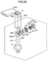
- Fig. 2B is an illustration of the construction of an optical system for illustrating the optical type sensor unit.
- the optical type sensor unit is comprised of a multimode laser diode LD, a non-polarizing beam splitter NBS, a probe-like polarizing prism PBS, a reference reflecting surface M, a quarter wavelength plate QWP, a light beam diameter limiting opening AP, a light beam amplitude splitting diffraction grating GBS, polarizing plates PP1-PP4, photoelectric elements PD1-PD4, etc.
- Divergent light from the multimode laser diode LD is made into a loosely condensed light beam BEAM by a collimator lens COL, is transmitted through the non-polarizing beam splitter NBS, and then enters the probe-like polarizing prism PBS of an optical probe NCP which is formed of a light-transmitting substance, and is splitted into each polarized component by the light splitting surface of the probe-like polarizing prism PBS.
- the reflected S-polarized light beam is condensed and illuminated near a beam waist on the side of the head arm ARM1 disposed in a space spaced apart by about 300 ⁇ m from the end surface of the probe-like polarizing prism PBS (here, the arm portion for the magnetic head for the underside of the lowermost hard disc), and the reflected light becomes a divergent spherical wave and returns along the original optical path, and is returned to the light splitting surface of the probe-like polarizing prism PBS.
- a P-polarized light beam transmitted through the probe-like polarizing prism PBS is condensed and illuminated on the reflecting deposited film of the end surface at a position deviating from the beam waist (short of the beam waist), and the reflected light returns along the original optical path, and is returned to the light splitting surface of the probe-like polarizing prism PBS.
- the optical path lengths of the two optical paths are set so that the difference between the optical path lengths thereof may be within the coherent distance of the light source, that is, the optical path lengths may be equal to each other.
- the shape is given as follows.
- the refractive index of the glass is 1.5.
- the condensed position (beam waist) of the light beam is set to a position of 0.3 mm after the light beams have emerged from the polarizing prism.
- the position of the wave source of the divergent spherical wave reflected from the head arm side and the reference reflecting surface looks deviated in the direction of the optical axis.
- the two positions are positions seen in the glass. Consequently, it follows that the two divergent spherical wave sources deviate by 0.5 mm from each other (a difference in the imaging optical path length is created), and when the two light beams are superposed one upon the other, the wavefronts do not completely coincide with each other, and if the two polarized lights are put together, there will be obtained interference fringes like concentric circles.
- the interference fringes like concentric circles look gushing out of and inhaled into the center.
- these concentric circular interference fringes are as small as about 0.5 mm in the amount of deviation of the two divergent spherical waves in the direction of the optical axis and therefore, in the central portion thereof, there is widely obtained an interference fringe portion of substantially one color (the same phase). Consequently, an appropriate opening AP is provided so as to take out only the substantially one color portion, thereby taking out some light beam. After this, the interference fringes can be handled as a substantially plane wave.
- the two light beams combined together by the probe-like polarizing prism PBS are linearly polarized lights orthogonal to each other and therefore, actually they do not intactly interfere with each other, and even if they are detected, they do not become light-and-shade signals.
- the two light beams reflected by the non-polarizing beam splitter NBS when transmitted through the quarter wavelength plate QWP, the linearly polarized lights orthogonal to each other are converted into circularly polarized lights of opposite directions, and when the vibration surfaces of the two are vector-combined, they are converted into a rotating linearly polarized light by the fluctuation of the phase difference between the two.
- This rotating linearly polarized light passes through the aforementioned opening AP, whereafter it is amplitude-splitted into four light beams (here ⁇ first-order diffracted lights created in each of two directions orthogonal to each other) by a phase diffraction grating having staggered grating structure (i.e., a phase diffraction grating having diffracting action in each of two directions orthogonal to each other). All of these light beams have their natures such as shape, intensity irregularity and defect entirely equally splitted by the amplitude division from the same area and therefore, even if for some reason or other, the interference fringes become not one color or are reduced in contrast, the influences thereof will all become equal.
- the reflected light from the head arm side has its wavefront disturbed by minute uneven structure and has intensity irregularity created strongly, but the ways of disturbance of the wavefronts and the states of intensity irregularity of the four light beams become equal.
- the phase diffraction grating is designed to avoid the creation of O-order light to the utmost.
- the light beams splitted into four are transmitted through polarizing plates (analyzers) disposed with their polarization azimuths deviated by 45° from each other, whereby it is converted into interference light in which the timing of light and shade deviates by 90° in terms of phase.
- the reductions in contrast by the influences of the disturbance of the wavefront and the intensity irregularity are all equally influenced.
- the light beams of light and shade are received by respective light receiving elements PD1, PD2, PD3 and PD4.
- the signals of the light receiving elements PD1 and PD2 having a phase difference of 180° therebetween are differentially detected, whereby a DC component (in which is contained a reduction in contrast or the like by the disturbance or the like of the wavefront) is substantially removed.
- This is an A phase signal.
- the signals of the light receiving elements PD3 and PD4 having a phase difference of 180° therebetween are differentially detected, and a DC component is substantially removed.
- the A and B phase signals have a phase difference of 90° therebetween, and the Lissajous waveform observed by an oscilloscope becomes circular.
- the amplitude of the Lissajous waveform (the size of the circle) fluctuates by the minute unevenness of the head arm side, but the central position thereof does not fluctuate. Consequently, no error is not essentially created in the phase detection (measurement of the relative distance).
- these A and B phase signals have the value of their DC component O binarized as a threshold value by a binarizing circuit, not shown, but even if an amplitude fluctuation occurs to the original A and B phase signals, the DC component remains O and does not fluctuate and therefore, no fluctuation occurs to the phase of the binarized signal and consequently, by the use of this binarized signal of which the phase has been stabilized, highly accurate position detection can be executed by the signal processor SP2.
- the present position detecting sensor operates as an interference type position detecting sensor which does not require the adjustment of the head arm side and the illuminating light beam and which is very easy to handle.
- the illuminating position deviation (parallel deviation) is not concerned with the phase deviation of the divergent spherical wave, it becomes the fluctuation of the amplitude of the interference signal due to a change in the minute uneven state of the head arm conforming to the illuminating position.
- the central position of the Lissajous waveform does not fluctuate and therefore, no error is not essentially created in the phase detection.
- the positional relation between the head arm and the position detecting sensor is such that both of them are rotatively moved about rotary shafts coaxial with each other and they do not deviate from each other as long as the distance between the two is kept constant.
- a shaft deviation error there occurs a relative positional relation (angular deviation and parallel deviation) during the rotation of the two.
- no problem essentially arises even if alignment deviation or parallel deviation occurs.
- the signal to finally be detected has its principles based on the interference measured length by the reciprocative optical path and therefore is a sine wave-like signal having a half of the wavelength of the light source as its period.
- a laser diode of a wavelength 0.78 ⁇ m is used, there is obtained a sine wave signal having a period of 0.39 ⁇ m (i.e., a sine wave each time the spacing between the side of the head arm ARM1 and the optical probe NCP varies by 0.39 ⁇ m), and the fluctuation of the relative distance can be detected by counting the wave number.
- phase difference of 90° therebetween
- two phases (A and B phases) of sine wave signals having a phase difference of 90° therebetween are obtained in the aforedescribed manner and therefore, by counting the signals after electrically splitting the signal by a well known electrical phase splitting device, the relative position deviation of more minute resolving power can be detected. If the signal is electrically splitted into 4096 pieces, the relative position deviation can be detected up to minimum 0.095 mm.
- the signal processor SP2 supplies a control current to a head arm driving motor (voice coil) VCM through a motor driver VCMD so that the relative position deviation detected in this manner may become zero.
- a head arm driving motor voice coil
- VCMD motor driver
- an optical probe NCP as a position detecting sensor mounted near the side of the head arm having a radius of 30 mm can be positioned with resolving power several times as great as ⁇ 1.4 nm.
- the positioning resolving power of the two as combined together is at the level of the performance of the highly accurate rotary positioner itself.
- the arm ARM2 is rotated by the motor MO to thereby move the optical probe NCP while taking feedback control by the system of the rotary encoder RE, the signal processor SP and the motor driver MD, and the magnetic head arm ARM1 is displaced by the system of the signal processor SP2, the motor driver VCMD and the head arm driving motor VCM so as to negate the displacement at this time, to thereby position the magnetic head arm while sequentially finely feeding it, and servo track signals from the signal generator SG are successively written in from the magnetic head.
- the interference between the reflected light beam from the side of the head arm and the reflected light beam from the reference reflecting surface is obtained within the coherence distance of the light source.
- a single-mode laser diode has a long coherence distance, but may sometimes cause mode hop to give rise to a phenomenon that the interference phase hops and therefore, in the present embodiment, a multimode laser is used and the optical path lengths are made substantially equal, and the multimode laser is used at an optical path length difference less than the coherence distance.
- generally the full width of the coherence distance is given by splitting the square of ⁇ 0 by ⁇ and therefore is about ⁇ 50 ⁇ m centering around the equal optical path length.
- the optical path length difference can be realized at ⁇ 10 ⁇ m and the measurement error in that case is ⁇ 1 nm. This value is sufficient accuracy as a servo track writer.
- a laser interference length measuring apparatus is not stable in its signal output due to fluctuation or the like when the optical paths thereof are generally separate and constructed while being exposed in the air.
- most of the interference optical path is a common optical path and is separated into two optical paths near the tip end of the probe-like polarizing prism, but is minute and in a glass medium and is constructed so that the influence of fluctuation or the like may become very small.
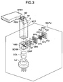
- Fig. 3 is an illustration of the construction of an optical system according to Embodiment 2 in which the probe-like polarizing prism has been changed in shape to cope with a case where the side of the head arm is proximate to the surface of the hard disc.
- the construction of Embodiment 2 is similar to that of Embodiment 1 and therefore need not be shown and described.
- a parallel glass plate G with reflecting film is joined to that portion of the probe-like polarizing prism PBS which is immediately behind the splitted surface thereof, and a P-polarized light beam transmitted through the splitted surface of the probe-like polarizing prism PBS is reflected by reflecting film M1, and is again transmitted through the polarizing film and impinges on partial reflecting film M2 provided on the side of the optical probe NCP, and returns along the original optical path.
- An S-polarized light beam reflected by the splitted surface of the probe-like polarizing prism PBS goes out of the optical probe NCP as in the aforedescribed embodiment, and is condensed and illuminated on the side of the head arm ARM1, and the reflected light thereof returns along the original optical path.
- the distance (see Fig. 2A) between the tip end of the optical probe NCP and the underside of the lowermost hard disc HD can be widened, and measurement also becomes possible on the side of a magnetic head arm of a type in which the magnetic head arm is proximate to the surface of the hard disc. It will be most effective if as shown in Fig. 3, the end portion of the parallel glass plate G is worked into 45°.
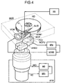
- Fig. 4 schematically shows the construction of a servo track signal writing-in apparatus according to Embodiment 3 of the present invention.
- members similar to those in the aforedescribed embodiments are given the same reference characters. Although partly repeated, the present embodiment will hereinafter be described in detail.
- a hard disc drive device HDD has mounted thereon a magnetic head arm ARM1 having a rotary shaft O outside hard discs HD, and a slider SLID mounted on the tip end thereof is disposed with a gap of 0.5 ⁇ m (or less) in opposed relationship with the surface of the hard discs, and is arcuately moved by the rotation of the magnetic head arm ARM1.
- the rotation is effected by an electric current being supplied to a voice coil motor VCM.
- Such an apparatus is disposed at a spatially proper position as shown in Fig. 4 relative to the hard disc drive device HDD comprising the hard discs HD, the slider SLID, the magnetic head arm ARM1, the voice coil motor VCM, etc.
- SG designates a signal generator for generating servo track signals to be written into the hard discs, and the servo track signals are written into the hard discs HD through the magnetic head of the slider SLID.
- a position detecting unit NCPU is provided on a support arm ARM2, and the tip end portion of an optical probe NCP is inserted in the slot-like opening (not shown) of the base plate of the hard disc drive device HDD and is disposed near the side of the magnetic head arm ARM1.
- the support arm ARM2 is disposed so as to be rotatively movable by a rotary shaft coaxial with the center of rotation O of the magnetic head arm ARM1.
- the rotated position of the position detecting unit NCPU is detected by a high resolving power rotary encoder RE mounted on the rotary shaft of the support arm ARM2, and on the basis of this detection data, a signal processor SP1 rotatively drives a motor MO through a motor driver MD.
- the position detecting sensor unit NCPU is rotatively positioned by this form of feedback control.
- the position detecting unit NCPU is comprised of an optical type sensor unit as will hereinafter be described.
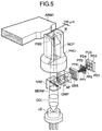
- Fig. 5 is an illustration of the construction of an optical system for illustrating the optical type sensor unit.
- the optical type sensor unit is comprised of a multimode laser diode LD, a non-polarizing beam splitter NBS, a probe-like polarizing prism PBS, a probe holder PHD, a reference reflecting surface M, a quarter wavelength plate QWP, a light beam diameter limiting opening AP, a light beam amplitude splitting diffraction grating GBS, polarizing plates PP1-PP4, photoelectric elements PD1-PD4, etc.
- Divergent light from the multimode laser diode LD is made into a loose condensed light beam BEAM by a collimator lens COL, and is transmitted through the non-polarizing beam splitter NBS and then impinges on the probe-like polarizing prism PBS of the optical probe NCP which is formed of a light transmitting substance, and is splitted into each polarized component by the light splitting surface of the probe-like polarizing prism PBS.
- a reflected S-polarized light beam is condensed and illuminated near the beam waist on the side of the head arm ARM1 (here, the arm portion for the magnetic head for the underside of the lowermost hard disc) disposed in a space spaced apart by about 300 ⁇ m from the end surface of the probe-like polarizing prism PBS, and the reflected light becomes a divergent spherical wave and returns along the original optical path, and is returned to the light splitting surface of the probe-like polarizing prism PBS.
- the head arm ARM1 here, the arm portion for the magnetic head for the underside of the lowermost hard disc
- a P-polarized light beam transmitted through the probe-like polarizing prism PBS is condensed and illuminated at a position deviating from the beam waist (a state short of the beam waist) on the reflecting deposited film of the end surface, and the reflected light returns along the original optical path and is returned to the light splitting surface of the probe-like polarizing prism PBS.
- the respective optical path lengths of the two optical paths are set so that the optical path length difference therebetween may be within the coherence distance of the light source, that is, the optical path lengths may be substantially equal to each other.
- the shape is given as follows.
- the condensed position (beam waist) of the light beam is set to a position of 0.3 mm after the light beam has emerged from the polarizing prism.
- the position of the wave source of a divergent spherical wave reflected from the head arm side and the reference reflecting surface looks deviated in the direction of the optical axis.
- the both positions are positions seen in the glass. Consequently, the two divergent spherical wave sources deviate by 0.5 mm from each other in the glass (an imaging optical path length difference is created), and when the two light beams are superposed one upon the other, the wavefronts do not completely coincide with each other, and if the two polarized lights are put together, there will be obtained concentric circular interference fringes.
- the concentric circular interference fringes look gushing out of or inhaled into the center.
- an interference fringe portion of substantially one color (the same phase) is widely obtained because the amount of deviation between the two divergent spherical waves in the direction of the optical axis is as small as about 0.5 mm. Consequently, an appropriate opening AP is provided so as to take out only the substantially one color portion to thereby take out some of the light beam. Thereafter, it can be handled as a substantially plane wave.
- the two light beams combined together by the probe-like polarizing prism PBS are linearly polarized lights orthogonal to each other and therefore, actually they do not intactly interfere with each other, and even if they are detected, they do not become light and shade signals.
- the two light beams reflected by the non-polarizing beam splitter NBS when transmitted through the quarter wavelength plate QWP, are converted from linearly polarized lights orthogonal to each other into circularly polarized lights of opposite directions, and when the vibration surfaces of the two are vector-combined, they are converted into a linearly polarized light rotated by the fluctuation of the phase difference between the two.
- This rotated linearly polarized light passes through the aforementioned opening AP, whereafter it is amplitude-splitted into four light beams (here ⁇ first-order diffracted lights created in each of two directions orthogonal to each other) by a phase diffraction grating having staggered grating structure (i.e., a phase diffraction grating having diffracting action in each of two directions orthogonal to each other).
- a phase diffraction grating having staggered grating structure i.e., a phase diffraction grating having diffracting action in each of two directions orthogonal to each other.
- the reflected light from the head arm side has its wavefront disturbed by minute uneven structure and intensity irregularity occurs strongly, but the ways of disturbance and the states of intensity irregularity of the wavefronts of the four light beams are equal.
- the phase diffraction grating is designed to avoid the creation of 0-order light to the utmost at the same time.
- the light beams splitted into four are transmitted through polarizing plates (analyzers) having their polarization azimuths disposed with a deviation of 45° with respect to one another, whereby it is converted into interference lights in which the timing of light and shade deviates by 90° in terms of phase.
- the reductions in contrast by the influences of the disturbance of the wavefront and the intensity irregularity are all equally influenced.
- the respective light and shade light beams are received by the respective light receiving elements PD1, PD2, PD3 and PD4.
- the signals of the light receiving elements PD1 and PD2 having a phase difference of 180° therebetween are differentially detected, whereby a DC component (including a contrast reduction by the disturbance or the like of the wavefront) is substantially eliminated.
- This is an A phase signal.
- the signals of the light receiving elements PD3 and PD4 having a phase difference of 180° therebetween are differentially detected, whereby a DC component is substantially removed.
- This is a B phase signal.
- the A and B phase signals have a phase difference of 90° therebetween, and the Lissajous waveform observed by means of an oscilloscope becomes circular.
- the amplitude of the Lissajous waveform (the size of the circle) is fluctuated by the minute unevenness of the head arm side, but its central position is not fluctuated. Consequently, essentially no error occurs to the phase detection (the measurement of the relative distance).
- these A and B phase signals have the value of their DC component 0 binarized as a threshold level by a binarizing circuit, not shown, but even if an amplitude fluctuation occurs to the original A and B phase signals, the DC component remains 0 and is not fluctuated and therefore, no fluctuation occurs to the phase of the binarized signal and consequently, by the use of this binarized signal stable in phase, highly accurate position detection can be executed by the signal processor SP2.
- the light is condensed and illuminated on the head arm side to thereby avoid the influence of the fluctuation (one-color deviation) of the interference state by the relative angle deviation (alignment deviation) of the head arm side. That is, by the light being condensed and illuminated, even if there is alignment deviation, the main emergence azimuth of the divergent spherical wave only somewhat deviates and the eclipse of the spherical wave itself is avoided, and also the overlapping state of the wavefronts of the two divergent spherical waves does not change and therefore, the interference state is obtained stably. Consequently, the sensor operates as an interference type position detecting sensor in which the adjustment of the head arm side and the illuminating light beam is unnecessary and which is very easy to handle.
- the illuminating position deviation (parallel deviation) is not concerned in the phase deviation of the divergent spherical wave, but becomes the fluctuation of the interference signal amplitude due to a minute change in the uneven state of the head arm conforming to the illuminating position.
- the central position of the Lissajous waveform does not fluctuate and therefore, essentially no error occurs to the phase detection.
- the positional relation between the head arm and the position detecting sensor does not deviate as long as they are rotatively moved about the rotational axes thereof coaxial with each other and the distance between the two is kept constant.
- the two axes cannot be completely coaxial with each other and therefore, due to an axis deviation error, the relative positional relation causes angular deviation and parallel deviation when the two are being rotated.
- essentially no problem will arise even if alignment deviation and parallel deviation occur.
- the finally detected signal has its principle based on the interference measured length by the reciprocative optical path and therefore is a sine wave-like signal having a half of the wavelength of the light source as its period.
- a laser diode of a wavelength 0.78 ⁇ m is used, there is obtained a sine wave signal having a period of 0.39 ⁇ m (i.e., a sine wave each time the spacing between the side of the head arm ARM1 and the optical probe NCP changes by 0.39 ⁇ m), and by counting the wave number, the fluctuation of the relative distance can be detected.
- sine wave signals having a phase difference of 90° therebetween are obtained in two phases (A and B phases) in the aforedescribed manner and therefore, by electrically splitting the signals by a well known electrical phase splitting device and thereafter counting them, relative positional deviation of finer resolving power can be detected. If the signals are electrically splitted into 4096 pieces, the relative positional deviation can be detected up to minimum 0.095 nm.
- the signal processor SP2 supplies a control current to the head arm driving motor (voice coil) VCM through the motor driver VCMD so that the relative positional deviation detected in this manner may become zero.
- the position of the magnetic head arm ARM1 relative to the optical probe NCP can be held (servo can be applied) stably at about several times as great as ⁇ 0.095 nm.
- the optical probe NCP as a position detecting sensor mounted near the head arm side of a radius 30 mm can be positioned with resolving power several times as great as ⁇ 1.4 nm.
- the stabilization of the relative position of the position detecting sensor itself is at about several times as great as ⁇ 0.095 nm as described above and therefore, the positioning resolving power resulting from the two having been put together becomes about equal to the performance of the highly accurate rotary positioner itself.
- the writing-in of signals is done by rotating the arm ARM2 by the motor MO to thereby move the optical probe NCP while taking feedback control by the system of the rotary encoder RE, the signal processor SP and the motor driver MD, and displacing the magnetic head arm ARM1 by the system of the signal processor SP2, the motor driver VCMD and the head arm driving motor VCM so as to negate the displacement at this time to thereby position the magnetic head arm while sequentially minutely feeding it, and writing the servo track signals from the signal generator SG in succession by the magnetic head.
- the interference between the reflected light beam from the head arm side and the reflected light beam from the reference reflecting surface is obtained within the coherence distance of the light source.
- a single mode laser diode has a long coherence distance but may cause mode hop and in some cases, the phenomenon of the interference phase thereof flying may happen and therefore, in the present embodiment, a multimode laser is used to make the optical path lengths substantially equal, and is used at an optical path length difference less than the coherence distance.
- the full width of the coherence distance is given by the square of ⁇ 0 having been splitted by ⁇ and therefore, is about ⁇ 50 ⁇ m centering around the equal optical path lengths.
- a laser interference length measuring apparatus when a laser interference length measuring apparatus is generally constructed with optical paths separated and exposed in the air, the signal output thereof is not stable due to fluctuation or the like.
- most of the interference optical paths is a common optical path, and although the common optical path is separated into two optical paths near the tip end of the probe-like polarizing prism, it is minute and within a glass medium, and design is made such that the influence of fluctuation or the like becomes very small.
- the probe-like polarizing prism PBS is joined to a probe holder PHD and is fixed onto the rotary positioner arm ARM2 with the position detecting device body.
- the probe holder PHD is inserted in a portion of a cylindrical metallic member which is hollowed, and is adhesively secured in such a manner that the parallelopiped-like polarizing prism PBS is sandwiched from its opposite sides by a structure of a D-shaped cross-section.
- a hole extends like a tunnel through a portion of the pedestal of the probe holder PHD through which the light passes.
- the light beam emergence side end surface of the member of the substantially D-shaped cross-section of the probe holder PHD is so shaped and disposed as to fly out of the light beam emergence surface of the polarizing prism PBS by the order of 100 ⁇ m as a specific example of numerical value.
- the spacing between the light beam emergence surface of the polarizing prism PBS and the side of the head arm ARM1 satisfies the range of the order of 0.3 mm ⁇ 0.05, a periodic signal of 1/2 of the wavelength of the light source is obtained in conformity with that spacing, but when the position detecting device and the head arm are disposed in a space at first, the relative positional relation therebetween is indefinite, and the distance between the light beam emergence surface of the polarizing prism PBS and the side of the head arm ARM1 must be set by some means so as to satisfy the range of the order of 0.3 mm ⁇ 0.05. At that time, a case where the two contact with each other is also supposed. However, by adopting the probe holder PHD of holding guide structure like that of the present embodiment, the probe-like polarizing prism PBS itself which is an optical member can be prevented from contacting and being damaged and creating positional deviation.
- the probe holder can be made very small and therefore can be made into a size equal to that of the push rod (PROD) of the servo track signal writing-in apparatus of the conventional art push rod type.
- PROD push rod
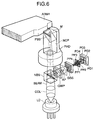
- Fig. 6 is an illustration of the construction of an optical system according to Embodiment 4 in which the probe-like polarizing prism holder PHD has been changed in shape
- the construction of this embodiment is similar to that of the aforedescribed Embodiment 1 and therefore need not be shown and described.
- the D-shaped holding portions are singularized and the contacting portion is made into a cylindrical surface.
- This specification discloses an apparatus comprising a first system for forming a composite light beam of two light beams to be made to interfere with each other, a splitting member for amplitude-splitting the composite light beam into three or more splitted light beams in the same area, and a second system for obtaining interference light beams of different phases from the plurality of splitted light beams.
- the specification also discloses an apparatus for effecting information recording on a hard disc drive device comprising an optical system for splitting a light beam into two light beams, causing one of the two light beams to be condensed and reflected by the side of an arm for a recording reading head in the hard disc drive device, and superposing the condensed and reflected light beam on the other light beam to thereby obtain a composite light beam, a splitting member for amplitude-splitting the composite light beam into three or more splitted light beams in the same area, an optical member for obtaining interference light beams of different phases from the plurality of splitted light beams, light receiving elements for detecting respective ones of the interference light beams of different phases, a control system for effecting the positioning of the arm on the basis of the result of the detection by each of the light receiving elements, and signal writing-in means for writing a signal into a hard disc through the recording reading head each time the arm is positioned.
Landscapes
- Length Measuring Devices By Optical Means (AREA)
- Optical Recording Or Reproduction (AREA)
- Optical Head (AREA)
- Moving Of Head For Track Selection And Changing (AREA)
Applications Claiming Priority (6)
| Application Number | Priority Date | Filing Date | Title |
|---|---|---|---|
| JP256788/97 | 1997-09-22 | ||
| JP25678897A JP3943668B2 (ja) | 1997-09-22 | 1997-09-22 | 干渉装置、位置検出装置、位置決め装置およびそれを用いた情報記録装置 |
| JP25678697 | 1997-09-22 | ||
| JP9256786A JPH1194513A (ja) | 1997-09-22 | 1997-09-22 | 干渉装置、位置検出装置、位置決め装置およびそれを用いた情報記録装置 |
| JP256786/97 | 1997-09-22 | ||
| JP25678897 | 1997-09-22 |
Publications (3)
| Publication Number | Publication Date |
|---|---|
| EP0903559A2 true EP0903559A2 (de) | 1999-03-24 |
| EP0903559A3 EP0903559A3 (de) | 2000-11-08 |
| EP0903559B1 EP0903559B1 (de) | 2006-05-31 |
Family
ID=26542891
Family Applications (1)
| Application Number | Title | Priority Date | Filing Date |
|---|---|---|---|
| EP98117859A Expired - Lifetime EP0903559B1 (de) | 1997-09-22 | 1998-09-21 | Informationsaufzeichnungsapparat mit Interferenzvorrichtung zur Positionsbestimmung und Positionierung |
Country Status (3)
| Country | Link |
|---|---|
| US (1) | US6631047B2 (de) |
| EP (1) | EP0903559B1 (de) |
| DE (1) | DE69834694T2 (de) |
Cited By (8)
| Publication number | Priority date | Publication date | Assignee | Title |
|---|---|---|---|---|
| EP1052475A2 (de) * | 1999-05-10 | 2000-11-15 | Canon Kabushiki Kaisha | Interferometer,Wegmessapparat und Gerät zur Informationsaufzeichnung und/oder -Wiedergabe unter Verwendung desselben |
| EP1037019A3 (de) * | 1999-03-12 | 2001-11-07 | Canon Kabushiki Kaisha | Interferenz-Messapparat |
| WO2002025643A3 (en) * | 2000-09-19 | 2002-07-11 | Microesystems Inc | Interface component a positioning system and method for designing an interface component |
| US6618218B1 (en) * | 1999-09-07 | 2003-09-09 | Canon Kabushiki Kaisha | Displacement detecting apparatus and information recording apparatus |
| WO2005085748A1 (en) * | 2004-03-04 | 2005-09-15 | Renishaw Plc | Optical readhead |
| EP1113243A3 (de) * | 1999-12-27 | 2005-11-09 | Canon Kabushiki Kaisha | Optischer Interferenz- und Positionsdetektionsapparat |
| US12431161B1 (en) | 2024-03-27 | 2025-09-30 | Western Digital Technologies, Inc. | Data storage device with track pitch determination for mitigating effects of servo pattern distortion |
| US12512122B2 (en) | 2024-03-21 | 2025-12-30 | Western Digital Technologies, Inc. | Data storage device with servo burst signal correction for mitigating effects of servo pattern distortion |
Families Citing this family (14)
| Publication number | Priority date | Publication date | Assignee | Title |
|---|---|---|---|---|
| JP4298093B2 (ja) * | 1999-11-10 | 2009-07-15 | キヤノン株式会社 | 光学式回転位置情報検出装置 |
| JP4846909B2 (ja) * | 2000-02-15 | 2011-12-28 | キヤノン株式会社 | 光学式エンコーダ及び回折格子の変位測定方法 |
| US6798613B1 (en) * | 2001-07-09 | 2004-09-28 | Maxtor Corporation | Method of correcting Z-height errors during assembly of a hard disk drive |
| JP3577054B2 (ja) * | 2002-03-27 | 2004-10-13 | ローム株式会社 | 光ピックアップ及び光ピックアップの製法並びに光ディスクシステム |
| US20070073317A1 (en) * | 2005-07-07 | 2007-03-29 | Don Tanaka | System for interconnecting hollow bodies |
| US7215504B1 (en) | 2005-10-19 | 2007-05-08 | Western Digital Technologies, Inc. | Disk drive using an optical sensor to detect a position of an actuator arm |
| US7619844B1 (en) | 2005-12-30 | 2009-11-17 | Western Digital Technologies, Inc. | Disk drive comprising a mechanical position sensor to prevent a runaway condition |
| US7495857B1 (en) | 2005-12-30 | 2009-02-24 | Western Digital Technologies, Inc. | Servo writing a disk drive by writing spiral tracks using a mechanical position sensor |
| US7365932B1 (en) | 2005-12-30 | 2008-04-29 | Western Digital Technologies, Inc. | Disk drive comprising an optical sensor for vibration mode compensation |
| US7480116B1 (en) | 2006-01-20 | 2009-01-20 | Western Digital Technologies, Inc. | Disk drive employing coarse position feedback from mechanical position sensor to improve format efficiency |
| JP2008077772A (ja) * | 2006-09-21 | 2008-04-03 | Fujitsu Ltd | 垂直磁気記録媒体、その製造方法及び磁気記録装置 |
| JP5504068B2 (ja) * | 2010-06-23 | 2014-05-28 | Dmg森精機株式会社 | 変位検出装置 |
| WO2014022649A2 (en) * | 2012-08-02 | 2014-02-06 | Ninepoint Medical, Inc. | Aberration corrected short working distance optical probe with large confocal parameter |
| CN112557363B (zh) * | 2020-12-07 | 2022-05-31 | 山西大学 | 一种基于飞秒激光调制相位的单粒子快速识别方法 |
Family Cites Families (27)
| Publication number | Priority date | Publication date | Assignee | Title |
|---|---|---|---|---|
| US3716845A (en) | 1972-03-09 | 1973-02-13 | Honeywell Inc | Optical memory with interferometer tracking |
| US5283434A (en) | 1991-12-20 | 1994-02-01 | Canon Kabushiki Kaisha | Displacement detecting device with integral optics |
| US5390022A (en) | 1992-04-07 | 1995-02-14 | Canon Kabushiki Kaisha | Displacement information detection apparatus for receiving a divergent light beam |
| JP2899165B2 (ja) | 1992-05-15 | 1999-06-02 | キヤノン株式会社 | ドップラー速度計及び変位情報検出装置 |
| JP3254737B2 (ja) | 1992-06-17 | 2002-02-12 | キヤノン株式会社 | エンコーダー |
| JP3478567B2 (ja) | 1992-09-25 | 2003-12-15 | キヤノン株式会社 | 回転情報検出装置 |
| JP3210111B2 (ja) | 1992-12-24 | 2001-09-17 | キヤノン株式会社 | 変位検出装置 |
| JPH06194123A (ja) | 1992-12-24 | 1994-07-15 | Canon Inc | 変位検出装置 |
| JP3173208B2 (ja) | 1993-01-29 | 2001-06-04 | キヤノン株式会社 | 変位測定装置 |
| JP3083019B2 (ja) | 1993-03-05 | 2000-09-04 | キヤノン株式会社 | 光学装置及び速度情報検出装置 |
| JP3082516B2 (ja) | 1993-05-31 | 2000-08-28 | キヤノン株式会社 | 光学式変位センサおよび該光学式変位センサを用いた駆動システム |
| DE69433105T2 (de) | 1993-06-29 | 2004-04-01 | Canon K.K. | Geschwindigkeitsmesser und Anlage zur Positionserfassung |
| JP3028716B2 (ja) | 1993-09-29 | 2000-04-04 | キヤノン株式会社 | 光学式変位センサ |
| JP3530573B2 (ja) | 1994-04-27 | 2004-05-24 | キヤノン株式会社 | 光学式変位センサ |
| JP3491969B2 (ja) | 1994-06-27 | 2004-02-03 | キヤノン株式会社 | 変位情報測定装置 |
| JP3513247B2 (ja) | 1994-07-11 | 2004-03-31 | キヤノン株式会社 | 周波数シフター及びそれを用いた光学式変位計測装置 |
| JP3450446B2 (ja) | 1994-08-03 | 2003-09-22 | キヤノン株式会社 | 光学式変位検出装置 |
| US5815267A (en) | 1994-09-09 | 1998-09-29 | Canon Kabushiki Kaisha | Displacement information measuring apparatus in which a light-receiving condition on a photodetector is adjustable |
| JPH08210814A (ja) | 1994-10-12 | 1996-08-20 | Canon Inc | 光学式変位測定装置 |
| JPH08219812A (ja) | 1995-02-15 | 1996-08-30 | Canon Inc | 変位情報検出装置、変位情報検出用スケール及びこれを用いたドライブ制御装置 |
| US5796470A (en) | 1995-02-28 | 1998-08-18 | Canon Kabushiki Kaisha | Frequency shifter and optical displacement measuring apparatus using the frequency shifter |
| JP3492012B2 (ja) | 1995-03-09 | 2004-02-03 | キヤノン株式会社 | 変位情報検出装置 |
| JP3548275B2 (ja) | 1995-05-12 | 2004-07-28 | キヤノン株式会社 | 変位情報測定装置 |
| JPH08304430A (ja) | 1995-05-12 | 1996-11-22 | Canon Inc | 周波数シフタ及びそれを用いた光学式変位計測装置 |
| JPH09113523A (ja) | 1995-10-23 | 1997-05-02 | Canon Inc | ドップラー速度計及び駆動システム |
| JPH1079180A (ja) * | 1996-08-30 | 1998-03-24 | Canon Inc | 情報記録装置 |
| JP2000321021A (ja) * | 1999-05-10 | 2000-11-24 | Canon Inc | 干渉装置、変位測定装置、及びそれを用いた情報記録又は/及び再生装置 |
-
1998
- 1998-09-18 US US09/156,491 patent/US6631047B2/en not_active Expired - Fee Related
- 1998-09-21 DE DE69834694T patent/DE69834694T2/de not_active Expired - Lifetime
- 1998-09-21 EP EP98117859A patent/EP0903559B1/de not_active Expired - Lifetime
Cited By (11)
| Publication number | Priority date | Publication date | Assignee | Title |
|---|---|---|---|---|
| EP1037019A3 (de) * | 1999-03-12 | 2001-11-07 | Canon Kabushiki Kaisha | Interferenz-Messapparat |
| US6657181B1 (en) | 1999-03-12 | 2003-12-02 | Canon Kabushiki Kaisha | Optical element used in compact interference measuring apparatus detecting plurality of phase difference signals |
| US7034947B2 (en) | 1999-03-12 | 2006-04-25 | Canon Kabushiki Kaisha | Compact interference measuring apparatus for detecting the magnitude and direction of positional deviation |
| US7375820B2 (en) | 1999-03-12 | 2008-05-20 | Canon Kabushiki Kaisha | Interference measuring apparatus for detecting a plurality of stable phase difference signals |
| EP1052475A2 (de) * | 1999-05-10 | 2000-11-15 | Canon Kabushiki Kaisha | Interferometer,Wegmessapparat und Gerät zur Informationsaufzeichnung und/oder -Wiedergabe unter Verwendung desselben |
| US6618218B1 (en) * | 1999-09-07 | 2003-09-09 | Canon Kabushiki Kaisha | Displacement detecting apparatus and information recording apparatus |
| EP1113243A3 (de) * | 1999-12-27 | 2005-11-09 | Canon Kabushiki Kaisha | Optischer Interferenz- und Positionsdetektionsapparat |
| WO2002025643A3 (en) * | 2000-09-19 | 2002-07-11 | Microesystems Inc | Interface component a positioning system and method for designing an interface component |
| WO2005085748A1 (en) * | 2004-03-04 | 2005-09-15 | Renishaw Plc | Optical readhead |
| US12512122B2 (en) | 2024-03-21 | 2025-12-30 | Western Digital Technologies, Inc. | Data storage device with servo burst signal correction for mitigating effects of servo pattern distortion |
| US12431161B1 (en) | 2024-03-27 | 2025-09-30 | Western Digital Technologies, Inc. | Data storage device with track pitch determination for mitigating effects of servo pattern distortion |
Also Published As
| Publication number | Publication date |
|---|---|
| EP0903559A3 (de) | 2000-11-08 |
| US20030133219A1 (en) | 2003-07-17 |
| DE69834694T2 (de) | 2007-05-16 |
| DE69834694D1 (de) | 2006-07-06 |
| EP0903559B1 (de) | 2006-05-31 |
| US6631047B2 (en) | 2003-10-07 |
Similar Documents
| Publication | Publication Date | Title |
|---|---|---|
| EP0903559B1 (de) | Informationsaufzeichnungsapparat mit Interferenzvorrichtung zur Positionsbestimmung und Positionierung | |
| US6618218B1 (en) | Displacement detecting apparatus and information recording apparatus | |
| US5568337A (en) | Head positioning using a disk drive mounted to a rotating table | |
| EP0397202B1 (de) | Kodierer | |
| US6151185A (en) | Position detecting apparatus, positioning apparatus, and information recording apparatus using the same | |
| US6493170B1 (en) | Interference device and position detection device using the same | |
| US5930066A (en) | Information recording apparatus | |
| US6473184B1 (en) | Interferometer which divides light beams into a plurality of beams with different optical paths | |
| US6529278B2 (en) | Optical interference apparatus and position detection apparatus | |
| JPH03146822A (ja) | エンコーダー | |
| US7054095B2 (en) | Displacement detection apparatus, and magnetic recording apparatus and encoder using the displacement detection apparatus | |
| JP3943668B2 (ja) | 干渉装置、位置検出装置、位置決め装置およびそれを用いた情報記録装置 | |
| JPH1194513A (ja) | 干渉装置、位置検出装置、位置決め装置およびそれを用いた情報記録装置 | |
| JP2811816B2 (ja) | イメージローテータのサーボ回路 | |
| JPH10141917A (ja) | 位置検出装置と位置決め装置及びそれを用いた情報記録装置 | |
| JP2000310507A (ja) | 干渉装置 | |
| US7136241B2 (en) | Information writing device | |
| JPH11351822A (ja) | 干渉装置及びそれを用いた位置検出装置 | |
| JPH05198110A (ja) | ヘッド位置決め装置 | |
| JPH06302099A (ja) | ディスクの位置ずれ補正装置 | |
| JP2000283718A (ja) | 位置検出装置及びそれを用いた情報記録装置 | |
| JPH0335602B2 (de) | ||
| JPH1038519A (ja) | 回動物体の位置検出装置と位置決め装置及びそれを用いた情報記録装置 | |
| JPH1144507A (ja) | 回動物体の位置検出装置と位置決め装置及びそれを用いた情報記録装置 | |
| JPH1079181A (ja) | 情報記録装置 |
Legal Events
| Date | Code | Title | Description |
|---|---|---|---|
| PUAI | Public reference made under article 153(3) epc to a published international application that has entered the european phase |
Free format text: ORIGINAL CODE: 0009012 |
|
| AK | Designated contracting states |
Kind code of ref document: A2 Designated state(s): DE GB NL |
|
| AX | Request for extension of the european patent |
Free format text: AL;LT;LV;MK;RO;SI |
|
| PUAL | Search report despatched |
Free format text: ORIGINAL CODE: 0009013 |
|
| AK | Designated contracting states |
Kind code of ref document: A3 Designated state(s): AT BE CH CY DE DK ES FI FR GB GR IE IT LI LU MC NL PT SE |
|
| AX | Request for extension of the european patent |
Free format text: AL;LT;LV;MK;RO;SI |
|
| 17P | Request for examination filed |
Effective date: 20010320 |
|
| AKX | Designation fees paid |
Free format text: DE GB NL |
|
| 17Q | First examination report despatched |
Effective date: 20050530 |
|
| GRAP | Despatch of communication of intention to grant a patent |
Free format text: ORIGINAL CODE: EPIDOSNIGR1 |
|
| GRAS | Grant fee paid |
Free format text: ORIGINAL CODE: EPIDOSNIGR3 |
|
| GRAA | (expected) grant |
Free format text: ORIGINAL CODE: 0009210 |
|
| AK | Designated contracting states |
Kind code of ref document: B1 Designated state(s): DE GB NL |
|
| REG | Reference to a national code |
Ref country code: GB Ref legal event code: FG4D |
|
| REF | Corresponds to: |
Ref document number: 69834694 Country of ref document: DE Date of ref document: 20060706 Kind code of ref document: P |
|
| PLBE | No opposition filed within time limit |
Free format text: ORIGINAL CODE: 0009261 |
|
| STAA | Information on the status of an ep patent application or granted ep patent |
Free format text: STATUS: NO OPPOSITION FILED WITHIN TIME LIMIT |
|
| 26N | No opposition filed |
Effective date: 20070301 |
|
| PGFP | Annual fee paid to national office [announced via postgrant information from national office to epo] |
Ref country code: NL Payment date: 20140804 Year of fee payment: 17 |
|
| PGFP | Annual fee paid to national office [announced via postgrant information from national office to epo] |
Ref country code: GB Payment date: 20140924 Year of fee payment: 17 |
|
| GBPC | Gb: european patent ceased through non-payment of renewal fee |
Effective date: 20150921 |
|
| REG | Reference to a national code |
Ref country code: NL Ref legal event code: MM Effective date: 20151001 |
|
| PG25 | Lapsed in a contracting state [announced via postgrant information from national office to epo] |
Ref country code: GB Free format text: LAPSE BECAUSE OF NON-PAYMENT OF DUE FEES Effective date: 20150921 |
|
| PG25 | Lapsed in a contracting state [announced via postgrant information from national office to epo] |
Ref country code: NL Free format text: LAPSE BECAUSE OF NON-PAYMENT OF DUE FEES Effective date: 20151001 |
|
| PGFP | Annual fee paid to national office [announced via postgrant information from national office to epo] |
Ref country code: DE Payment date: 20160930 Year of fee payment: 19 |
|
| REG | Reference to a national code |
Ref country code: DE Ref legal event code: R119 Ref document number: 69834694 Country of ref document: DE |
|
| PG25 | Lapsed in a contracting state [announced via postgrant information from national office to epo] |
Ref country code: DE Free format text: LAPSE BECAUSE OF NON-PAYMENT OF DUE FEES Effective date: 20180404 |