EP0903539B1 - Brûleur avec régénérateur - Google Patents
Brûleur avec régénérateur Download PDFInfo
- Publication number
- EP0903539B1 EP0903539B1 EP98115221A EP98115221A EP0903539B1 EP 0903539 B1 EP0903539 B1 EP 0903539B1 EP 98115221 A EP98115221 A EP 98115221A EP 98115221 A EP98115221 A EP 98115221A EP 0903539 B1 EP0903539 B1 EP 0903539B1
- Authority
- EP
- European Patent Office
- Prior art keywords
- regenerator
- burner
- nozzle
- regenerator burner
- regenerators
- Prior art date
- Legal status (The legal status is an assumption and is not a legal conclusion. Google has not performed a legal analysis and makes no representation as to the accuracy of the status listed.)
- Expired - Lifetime
Links
Images

Classifications
-
- F—MECHANICAL ENGINEERING; LIGHTING; HEATING; WEAPONS; BLASTING
- F23—COMBUSTION APPARATUS; COMBUSTION PROCESSES
- F23D—BURNERS
- F23D14/00—Burners for combustion of a gas, e.g. of a gas stored under pressure as a liquid
- F23D14/46—Details
- F23D14/66—Preheating the combustion air or gas
-
- F—MECHANICAL ENGINEERING; LIGHTING; HEATING; WEAPONS; BLASTING
- F23—COMBUSTION APPARATUS; COMBUSTION PROCESSES
- F23C—METHODS OR APPARATUS FOR COMBUSTION USING FLUID FUEL OR SOLID FUEL SUSPENDED IN A CARRIER GAS OR AIR
- F23C3/00—Combustion apparatus characterised by the shape of the combustion chamber
- F23C3/002—Combustion apparatus characterised by the shape of the combustion chamber the chamber having an elongated tubular form, e.g. for a radiant tube
-
- F—MECHANICAL ENGINEERING; LIGHTING; HEATING; WEAPONS; BLASTING
- F23—COMBUSTION APPARATUS; COMBUSTION PROCESSES
- F23L—SUPPLYING AIR OR NON-COMBUSTIBLE LIQUIDS OR GASES TO COMBUSTION APPARATUS IN GENERAL ; VALVES OR DAMPERS SPECIALLY ADAPTED FOR CONTROLLING AIR SUPPLY OR DRAUGHT IN COMBUSTION APPARATUS; INDUCING DRAUGHT IN COMBUSTION APPARATUS; TOPS FOR CHIMNEYS OR VENTILATING SHAFTS; TERMINALS FOR FLUES
- F23L15/00—Heating of air supplied for combustion
- F23L15/02—Arrangements of regenerators
-
- F—MECHANICAL ENGINEERING; LIGHTING; HEATING; WEAPONS; BLASTING
- F23—COMBUSTION APPARATUS; COMBUSTION PROCESSES
- F23C—METHODS OR APPARATUS FOR COMBUSTION USING FLUID FUEL OR SOLID FUEL SUSPENDED IN A CARRIER GAS OR AIR
- F23C2900/00—Special features of, or arrangements for combustion apparatus using fluid fuels or solid fuels suspended in air; Combustion processes therefor
- F23C2900/03005—Burners with an internal combustion chamber, e.g. for obtaining an increased heat release, a high speed jet flame or being used for starting the combustion
-
- Y—GENERAL TAGGING OF NEW TECHNOLOGICAL DEVELOPMENTS; GENERAL TAGGING OF CROSS-SECTIONAL TECHNOLOGIES SPANNING OVER SEVERAL SECTIONS OF THE IPC; TECHNICAL SUBJECTS COVERED BY FORMER USPC CROSS-REFERENCE ART COLLECTIONS [XRACs] AND DIGESTS
- Y02—TECHNOLOGIES OR APPLICATIONS FOR MITIGATION OR ADAPTATION AGAINST CLIMATE CHANGE
- Y02E—REDUCTION OF GREENHOUSE GAS [GHG] EMISSIONS, RELATED TO ENERGY GENERATION, TRANSMISSION OR DISTRIBUTION
- Y02E20/00—Combustion technologies with mitigation potential
- Y02E20/34—Indirect CO2mitigation, i.e. by acting on non CO2directly related matters of the process, e.g. pre-heating or heat recovery
Definitions
- the invention relates to a regenerator burner, especially for heating furnace rooms of industrial furnaces.
- Industrial burners are among regenerative burners understood that work with regenerative air preheating and usually with two integrated regenerators work alternately with hot combustion gases and with cold combustion air in counterflow mode be charged.
- Such regenerator burners allow it higher air preheating than so-called recuperator burners to achieve, i.e., industrial burners, the one have built-in recuperator.
- the one with regenerative burners achievable, relative air preheating is up to 90%, i.e. at an exhaust gas inlet temperature of e.g.
- the combustion air can be preheated to approx. 900 ° C at 1000 ° C become.
- regenerator With this regenerative burner, the fuel lance is in one coaxial surrounding annulus a single coaxial flow through regenerator provided, the heat storage elements from individual, stacked, ceramic Regenerator discs exist.
- the regenerator is a ceramic combustion chamber downstream, which has a in cross-section approximately cloverleaf-shaped nozzle in the Oven chamber opens and in the gas and air until it is reached the ignition temperature in the furnace chamber (approx. 800 ° C) burned become. Then the gas supply for combustion in the Furnace room switched. Since the regenerator burner only with is equipped with a regenerator, it will then operated batchwise in two operating cycles. While a regenerator will be used in a first operating cycle blocked fuel and combustion air supply from hot furnace exhaust flows through the heat storage elements of the regenerator.
- regenerator burner is the arrangement hit in such a way that the fuel lance surrounds you with a radial spacing, coaxial air guide cylinder 6 regenerator cartridges are arranged in the burner-receiving opening of the furnace wall.
- each the regenerator cartridge consists of a number in terms of flow arranged one behind the other, one above the other stacked ceramic storage stones, the continuous Flow channels included.
- the regenerator cartridges are each with a tubular receiving the storage stones designed outer jacket made of sheet steel the one on the side facing the furnace chamber Connects nozzle chamber, in the bottom wall of two Nozzles are arranged.
- All nozzles of the regenerator cartridges lie on an imaginary coaxial to the fuel lance Circle, with neighboring nozzles having the same center distance exhibit.
- the nozzle chambers of the regenerator cartridges enclose one connected to the air guide cylinder ceramic combustion chamber into which the fuel lance empties.
- the combustion chamber allows the necessary in the furnace room To achieve ignition temperature of approx. 800 ° C.
- the regenerator cartridges are grouped into one of two Operating cycles operated, of which in one of them flows through the hot combustion gases and heated be while the stored heat in the other to the cold combustion air flowing through them. Remains between the cylindrical regenerator cartridges a considerable, unused gusset volume, so that the heat storage capacity of the regenerators is limited.
- regenerator burner known from EP 0 715 123 A2, where the two are within one to the central Fuel lance coaxial tube arranged regenerators in one embodiment of a number with their Axes lying on a common imaginary circle Regenerator cartridges formed and in another embodiment in a coaxial to the fuel lance Annulus are arranged by radial partitions is divided.
- the sector-shaped departments included the present as ceramic honeycomb stones, one above the other stacked heat storage elements.
- the alternate Actuation of the two regenerators thus formed with hot combustion gases or cold combustion air is done by a valve device, the two has perforated disks rotatable relative to one another.
- the invention has for its object to provide an industrial burner with regenerative air preheating, i.e. a so-called regenerator burner, which is characterized by a high heat storage capacity and due to its design also simple construction with regenerators arranged within a cylindrical outer tube is suitable for being able to be operated with low NO x emissions.
- the generator burner is used to solve this task According to the invention by the features of claim 1 characterized.
- the two regenerators are in the new generator burner concentric in two the fuel supply means surrounding annular spaces arranged at least over a Part of its axial length lying radially one inside the other surrounding outer cylindrical tube arranged are.
- the combustion air and the combustion exhaust gas are, as usual, periodically on the two regenerators switched.
- the switching valve for periodic Reversal of combustion air and combustion exhaust gas is usually located directly on the burner head.
- the regenerators Assigned nozzle means which alternate as one and Outlet nozzles are operable.
- These have a number annularly distributed nozzle openings on the with their central axes, at least approximately, towards one concentric to the fuel supply means Circle and which, if necessary in groups, with the Heat storage elements of one or the other regenerator stay in contact.
- You can in a preferred Embodiment by a substantially meandering shaped nozzle ring may be limited to that with a coaxial tube at least one of the two regenerators connected is.
- the nozzle means and at least that radially internal regenerator is expediently one Combustion chamber arranged in which a fuel supply device, leads especially for the start operation.
- the combustion gas fed to the combustion chamber while the associated regenerator is supplied with combustion air. That means while halving performance in time during the the furnace chamber is brought to operating temperature. In in practice, however, this is permissible in many cases.
- the outer regenerator can also with an annular combustion chamber and its own combustion gas supply what is achieved during full power is available during the heating phase stands. However, it also becomes a second ignition and Monitoring device necessary, what a certain Effort means.
- the nozzle means essentially contain those mentioned above meandering shaped nozzle ring, this can in simply made from thin-walled ceramic material and simply by plugging in the assigned one coaxial tube to be mounted, with the nozzle openings in it cover part to be defined radially inwards can be used. Due to the alternating and symmetrical Arrangement of the inlet / outlet nozzle openings of both Regenerators towards the furnace on a circular ring around the central fuel supply means (e.g. gas lance) good recirculation of the combustion gases in the furnace chamber or reached in a jet pipe.
- the central fuel supply means e.g. gas lance
- the new generator burner is particularly suitable for use with one leg closed at the end Jacket tube, a so-called jacket jet heating tube suitable. But it can also be used for the direct heating of an oven room be used. In this case the order is taken in such a way that in a corresponding Opening of the wall of the furnace chamber inserted regenerator burner that in the area of the inner wall side nozzle means located freely into the furnace chamber.
- the two regenerators of the new regenerator burner advantageously contain ring-shaped heat storage elements, contain axially flowable channels. To one uncontrolled breakage due to different thermal expansion, etc. to avoid, it is useful if the annular heat storage elements in sector-shaped ring segments are divided, which are arranged side by side are.
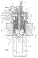
- the regenerator burner shown in the drawing is used to heat a furnace chamber 1, which is in the Cutout furnace wall 2 is limited, the one has continuous cylindrical opening 3.
- a ceramic jacket radiant tube 4 sealed used that protruding into the furnace chamber 1 Part is closed at 5 and the end molded ring flanges 6 and intermediate layers 7 against the Outside of the furnace wall 2 is supported.
- a coaxial burner head 8 is placed on the furnace wall 2, the steel housing 9 inside with heat-insulating material 10th is lined.
- a fuel distributor sits on the burner head 11 of which in the jacket radiant tube 4 projecting and coaxial to this fuel lance 12, the fuel supply means and the one above at 13 indicated valve fuel, usually natural gas or the like, can be supplied.
- the fuel lance 12 surrounding with a radial distance goes from that Fuel distributor 11, a fuel supply pipe 14 from that is shorter than the fuel lance 12 and over one Valve 15 also with fuel (natural gas or the like) can be applied.
- the fuel supply pipe 14 is made of a thin-walled one Ceramic material existing cylindrical inner tube 16 surrounded in radial distance, which ends sealed in the burner head 8 is used inside.
- the Inner tube 16 is against the fuel supply tube 14 poorly heat conductive, high temperature resistant, ceramic Material thermally insulated, as indicated at 17.
- the inner tube 16 is at a greater radial distance from a coaxial, made of thin-walled ceramic material surround second tube 18, the end at 19 an annular flange 20 is attached, via which it is attached to the Burner head 8 is supported.
- Coaxial to the second ceramic tube 18 is also made of thin-walled ceramic material existing outer cylindrical tube 21 is provided, connected at the end to an annular flange 22 and is held on the burner head 8.
- annular spaces 24, 25 are formed coaxially, radially one inside the other.
- annular spaces 24, 25 are arranged, each of which annular heat storage element 28 contains, which consist of ceramic material and their structure, can also be seen in particular from FIG.
- the annular heat storage elements 28 have axially continuous channels with a clear width of approx. 2 mm. They are divided into sector-shaped ring segments 29 which arranged abutting in the circumferential direction are. This will result in an uncontrolled break thermal stresses avoided. In the axial direction are the annular heat storage elements 28 separated from each other by small spaces 30 which determined by spacers not shown are. In addition, the heat storage elements 28 are each on an edge of the second tube 18 or the outer Supported tube 22, as shown in Figure 1 at 31 or 32 is shown.
- the figure also shows that the two regenerators 26, 27 over a considerable part their axial length overlapping each other within the Furnace wall 2 lie, the radial external regenerator 27 over almost its entire axial length in the outer tube 22 is received, while the radially inner Regenerator 26 is about half in the interior of the burner head 8 extends.
- the outer tube 21 is on the furnace chamber 1 facing Front side at 33 funnel-shaped towards the inside moved in, so that there is one towards the furnace chamber 1 has a tapered conical surface.
- a nozzle ring 34 ( Figure 1, 3) placed in the Folded essentially meandering and on its outer circumferential surface according to the slope of the inner wall of the funnel-shaped indented area 33, is designed.
- the nozzle ring 34 extends in the axial direction up to the second Tube 18 to which he puts on inside, like this Figure 1 can be seen.
- nozzle ring 34 In the nozzle ring 34 is a pot or cap-shaped end cover 35 used on the conical inner wall 36 of the nozzle ring 34 with a corresponding cone angle Circumferential area is supported and in the axial direction protrudes the nozzle ring 34 into the furnace chamber 1.
- the lid 35 has a central opening 37 through which the fuel lance 12 is carried out.
- the cover 35 only about half the axial height of the Nozzle ring 34, approximately up to one below the heat storage elements 28 of the radial outer regenerator 27 lying annular space 38 delimited by the tubes 18, 22.
- the funnel-shaped Area 33 of the outer tube 21 and inside through the Cover 35 limited area of that described in the Way used nozzle ring 34 are meandering in the folded nozzle ring 34 side by side, channel-like Nozzle openings 39, 40 limited in cross section are approximately trapezoidal and with their centers on an imaginary circle coaxial to the fuel lance 12 lie, which is indicated in Figure 3 at 41.
- nozzle openings 39, 40 are thus symmetrical and evenly distributed around the fuel lance 12 arranged.
- the nozzle openings 39 open into the Annulus 38 of the radially outer regenerator 27 while the adjacent nozzle openings 40 into a the fuel lance 12 lead coaxial combustion chamber 42, the limited by the tube 18, the nozzle ring 34 and the cover 35 is.
- the fuel supply pipe 14 which along with one the fuel lance 12 arranged baffle 43, a nozzle-like fuel outlet limited.
- the fuel lance passed through the combustion chamber 42 12 lying leads an ignition electrode into the combustion chamber 42 44 with assigned ionization monitoring, their assigned electrical connection device on the fuel distributor 11 sits and is designated 45.
- a coaxial ceramic flame tube 46 is arranged fixed by thin webs, as indicated at 47 is held.
- annular spaces 48, 25 separated axially from one another, of which the annular space 48 with the radially inner Regenerator 26 and the annular space 25 with the radial external regenerator 27 are connected.
- annular space 48 with the radially inner Regenerator 26 and the annular space 25 with the radial external regenerator 27 are connected.
- the via a changeover valve device 52 optionally with a Combustion air supply duct 53 or with a combustion exhaust duct 54 can be connected.
- regenerator burner basically works in EP 0 463 218 A3 and EP 0 685 683 A3 described by the applicant:
- the first step is Start operation of the furnace chamber 42 via the fuel supply pipe 14 and the radially inner regenerator 26 Fuel and combustion air supplied.
- the air / fuel mixture is ignited by the ignition electrode 44 and burned.
- the hot combustion gases pass through the Nozzle openings 39 into the jacket radiant tube 4, paint over the inner wall and are over the Nozzle openings 40, the annular space 38, the radially outer Regenerator 26 and the combustion gas discharge 54 dissipated.
- the ignition temperature approximately equal to the fuel supply pipe 14 the fuel lance opening outside the combustion chamber 42 12 unswitched (valves 13/15).
- the one from the fuel lance 12 escaping fuel (usually gas) is in the flame tube 46 and in the between these and the as Air cone for those emerging from the nozzle openings 39 Air jet acting cover 35 lying area oxidized, at the same time intensive mixing with by the impulse effect of the nozzle openings 39 escaping, intensely circulated hot exhaust gases he follows.
- the through the heat emission through the jacket radiant tube 4 Flue gases cooled in the furnace chamber 1 flow via the nozzle openings 40 acting as outlet nozzles, through the radially outer regenerator 27 and the Combustion gas exhaust line 54, the ceramic Heat storage elements 28 of this regenerator heated become.
- regenerator 27 As soon as the regenerator 27 is fully heated, switches the valve device 52 around, with the result that the Combustion air now flows through the hot regenerator 27 and is preheated while the hot combustion gases via the nozzle openings now acting as inlet nozzles 39 and the combustion chamber 42 the radially inner Flow through regenerator 26 and its ceramic Heat up heat storage elements 28.
- the nozzle openings 39, 40 of the nozzle ring 34 work thus intermittently as inlet and outlet nozzles, like this in Figure 1 is indicated by arrows, of which the arrows 55 the alternating flow through the nozzle openings 39 and the arrows 56 the alternate flow of the Illustrate nozzle openings 40.
- the generator burner shown in Figure 1 works with a jacket radiant tube 4 closed at the end, this as well as the flame tube 46 and the tubes 16, 18, 22 and the nozzle ring 34 and the cover 35 made of a thin-walled Ceramic material with a wall thickness of Rule 2 to 5 mm exist. Basically, the generator burner but also for direct heating of the furnace chamber 1 are used, the jacket radiant tube 4 then eliminated. Otherwise the arrangement basically remains as shown in Figure 1.
- regenererator 27 used during start-up become.
- the annular space 38 used as an annular combustion chamber which is why it is used with a (not further illustrated) fuel supply device and an ignition device is equipped.
Landscapes
- Engineering & Computer Science (AREA)
- Chemical & Material Sciences (AREA)
- Combustion & Propulsion (AREA)
- Mechanical Engineering (AREA)
- General Engineering & Computer Science (AREA)
- Gas Burners (AREA)
- Air Supply (AREA)
- Combustion Of Fluid Fuel (AREA)
Claims (12)
- Brûleur à régénérateur, en particulier pour le chauffage d'enceintes de four, dans des fours industriels, comprenant
un tube extérieur (21) dans lequel sont disposés des moyens d'alimentation en combustible (12) coaxiaux, centraux,
une tête de brûleur (8), qui comporte des dispositifs d'entrée d'air de combustion et d'évacuation des gaz de combustion (25, 48, 51, 50), et de laquelle part le tube extérieur (21),
deux régénérateurs (26, 27) qui peuvent être alimentés alternativement avec de l'air de combustion et des gaz de combustion,
les deux régénérateurs (26, 27) étant disposés dans deux chambres annulaires (24, 25), coaxiales avec les moyens d'alimentation en combustible (12), qui s'étendent à l'intérieur du tube extérieur (21) en entourant les moyens d'alimentation en combustible au moins sur une partie de leur longueur axiale, et sont montés l'un dans l'autre dans la direction radiale, ainsi que
des moyens formant buses (34; 39, 40) associés aux deux chambres annulaires (24, 25), qui sont disposés à l'extrémité opposée à la tête de brûleur (8) et peuvent fonctionner alternativement en buse d'entrée et en buse de sortie. - Brûleur à régénérateur selon la revendication 1, caractérisé en ce que chacun des deux régénérateurs (26, 27) comporte des éléments accumulateurs de chaleur (28) annulaires, qui sont pourvus de canaux à circulation axiale.
- Brûleur à régénérateur selon la revendication 2, caractérisé en ce que les éléments accumulateurs de chaleur (28) annulaires sont divisés en segments d'anneau (29) en forme de secteurs.
- Brûleur à régénérateur selon une des revendications précédentes, caractérisé en ce que, lorsque le brûleur à régénérateur est monté dans une ouverture adaptée (3) dans une paroi (2) d'une enceinte de four (1), les régénérateurs (26, 27) sont disposés au moins partiellement dans la région de la paroi de four (2).
- Brûleur à régénérateur selon une des revendications précédentes, caractérisé en ce que les moyens formant buses présentent un certain nombre d'orifices de buses (39, 40) répartis en anneau, dont les axes médians sont situés au moins approximativement sur un cercle imaginaire (41) concentrique avec les moyens d'alimentation en combustible (12), et qui alternativement - le cas échéant par groupes - communiquent avec les éléments accumulateurs de chaleur (28) de l'un ou de l'autre régénérateur (26, 27).
- Brûleur à régénérateur selon la revendication 5, caractérisé en ce que les orifices de buses (39, 40) sont délimités par un anneau de buse (34) conformé essentiellement avec des ondulations, qui est lié à un tube (21) coaxial avec au moins un des deux régénérateurs (26, 27).
- Brûleur à régénérateur selon la revendication 6, caractérisé en ce qu'un élément de fermeture (35), qui délimite les orifices de buse vers l'intérieur vu dans la direction radiale, est monté dans l'anneau de buse (34).
- Brûleur à régénérateur selon une des revendications précédentes, caractérisé en ce qu'entre les moyens formant buses (34; 39, 40) et au moins le régénérateur (26) intérieur, vu dans la direction radiale, est disposée une chambre de combustion (42) dans laquelle débouche un dispositif d'alimentation en combustible (14), en particulier pour le démarrage.
- Brûleur à régénérateur selon une des revendications précédentes, caractérisé en ce que des tubes (16, 18, 21), qui reçoivent au moins les moyens formant buses (34) et les éléments accumulateurs (28) des régénérateurs (26, 27), sont réalisés en un matériau céramique à paroi mince.
- Brûleur à régénérateur selon une des revendications précédentes, caractérisé en ce que lorsque le brûleur à régénérateur est monté dans une ouverture adaptée (3) dans une paroi (2) d'une enceinte de four (1), les moyens formant buses (34; 39, 40) disposés dans le voisinage de la face intérieure de la paroi débouchent librement dans l'enceinte de four (1).
- Brûleur à régénérateur selon une des revendications 1 à 7, caractérisé en ce qu'il comporte un tube de chauffage à rayonnement (4) fermé à une extrémité, dans lequel débouchent les moyens formant buses (34; 39, 40).
- Brûleur à régénérateur selon la revendication 11, caractérisé en ce que le tube de chauffage à rayonnement (4) est réalisé en un matériau céramique à paroi mince.
Applications Claiming Priority (2)
| Application Number | Priority Date | Filing Date | Title |
|---|---|---|---|
| DE19740788 | 1997-09-17 | ||
| DE19740788A DE19740788C1 (de) | 1997-09-17 | 1997-09-17 | Regeneratorbrenner |
Publications (3)
| Publication Number | Publication Date |
|---|---|
| EP0903539A2 EP0903539A2 (fr) | 1999-03-24 |
| EP0903539A3 EP0903539A3 (fr) | 1999-09-15 |
| EP0903539B1 true EP0903539B1 (fr) | 2003-05-14 |
Family
ID=7842571
Family Applications (1)
| Application Number | Title | Priority Date | Filing Date |
|---|---|---|---|
| EP98115221A Expired - Lifetime EP0903539B1 (fr) | 1997-09-17 | 1998-08-13 | Brûleur avec régénérateur |
Country Status (4)
| Country | Link |
|---|---|
| EP (1) | EP0903539B1 (fr) |
| JP (1) | JPH11148605A (fr) |
| KR (1) | KR19990029822A (fr) |
| DE (2) | DE19740788C1 (fr) |
Cited By (1)
| Publication number | Priority date | Publication date | Assignee | Title |
|---|---|---|---|---|
| RU2656220C1 (ru) * | 2013-11-20 | 2018-06-01 | ТЕНОВА С.п.А. | Саморегенерирующая промышленная горелка и промышленная печь для выполнения саморегенерирующихся процессов горения |
Families Citing this family (11)
| Publication number | Priority date | Publication date | Assignee | Title |
|---|---|---|---|---|
| KR100332694B1 (ko) * | 1999-09-13 | 2002-04-17 | 손재익 | 공기 유로 변환기를 구비한 축열식 복사형 가스 연소기 |
| EP1101924A1 (fr) | 1999-11-16 | 2001-05-23 | BHKW Betreiber GmbH & Co. Anlagen KG | Convertisseur d'énergie et son procédé de fonctionnement |
| KR100481369B1 (ko) * | 2000-03-13 | 2005-04-07 | 주식회사 포스코 | 축열식 버너장치 |
| ITMI20032327A1 (it) * | 2003-11-28 | 2005-05-29 | Techint Spa | Bruciatore a gas a basse emissioni inquinanti. |
| CZ302827B6 (cs) * | 2005-06-14 | 2011-11-30 | Kalousek@Zdenek | Regeneracní horákový systém |
| EP1995515B1 (fr) | 2007-05-23 | 2013-10-30 | WS-Wärmeprozesstechnik GmbH | Fonctionnement FLOX pris en charge et son brûleur |
| ITMI20112380A1 (it) * | 2011-12-23 | 2013-06-24 | Danieli Off Mecc | Sistema di combustione autorigenerativo a basse emissioni di nox |
| CN102563654A (zh) * | 2012-02-25 | 2012-07-11 | 佛山市科皓燃烧设备制造有限公司 | 一种自身蓄热式燃气烧嘴 |
| CN104109753A (zh) * | 2014-07-15 | 2014-10-22 | 河北钢铁股份有限公司唐山分公司 | 一种辊底炉用空气单蓄热式烧嘴 |
| EP3032171B1 (fr) | 2014-12-09 | 2018-01-31 | WS-Wärmeprozesstechnik GmbH | Tube en acier régénératif chauffé |
| US20210131662A1 (en) * | 2019-10-30 | 2021-05-06 | Honeywell International Inc. | Recuperative gas burner for industrial applications and method of operating the same |
Family Cites Families (8)
| Publication number | Priority date | Publication date | Assignee | Title |
|---|---|---|---|---|
| GB540797A (en) * | 1940-04-29 | 1941-10-30 | Howden James & Co Ltd | Improvements in or relating to air preheaters for use with boiler plant |
| US2795213A (en) * | 1954-12-30 | 1957-06-11 | Air Preheater | Zoned air heater |
| JPH0623605B2 (ja) * | 1987-05-26 | 1994-03-30 | 日本ファーネス工業株式会社 | ラジアントチューブバーナ |
| EP0463218B1 (fr) * | 1990-06-29 | 1994-11-23 | Joachim Dr.-Ing. Wünning | Procédé et dispositif de combustion du combustible dans une chambre de combustion |
| WO1995015462A1 (fr) * | 1993-12-03 | 1995-06-08 | Nippon Furnace Kogyo Kabushiki Kaisha | Bruleur du type a regeneration et systeme echangeur de chaleur associe du type a emmagasinage |
| DE4419332A1 (de) * | 1994-06-02 | 1995-12-14 | Wuenning Joachim | Industriebrenner mit geringer NO¶x¶-Emission |
| DE4420477C2 (de) * | 1994-06-11 | 2000-05-04 | Ws Waermeprozestechnik Gmbh | Industriebrenner mit regenerativer Luftvorwärmung |
| TW278124B (fr) * | 1994-10-14 | 1996-06-11 | Toyota Motor Co Ltd |
-
1997
- 1997-09-17 DE DE19740788A patent/DE19740788C1/de not_active Expired - Fee Related
-
1998
- 1998-08-13 DE DE59808336T patent/DE59808336D1/de not_active Expired - Lifetime
- 1998-08-13 EP EP98115221A patent/EP0903539B1/fr not_active Expired - Lifetime
- 1998-09-16 KR KR1019980038148A patent/KR19990029822A/ko not_active Withdrawn
- 1998-09-17 JP JP10263010A patent/JPH11148605A/ja active Pending
Cited By (2)
| Publication number | Priority date | Publication date | Assignee | Title |
|---|---|---|---|---|
| RU2656220C1 (ru) * | 2013-11-20 | 2018-06-01 | ТЕНОВА С.п.А. | Саморегенерирующая промышленная горелка и промышленная печь для выполнения саморегенерирующихся процессов горения |
| US10288285B2 (en) | 2013-11-20 | 2019-05-14 | Tenova S.P.A. | Self-regenerating industrial burner and industrial furnace for carrying out self-regenerating combustion processes |
Also Published As
| Publication number | Publication date |
|---|---|
| JPH11148605A (ja) | 1999-06-02 |
| DE19740788C1 (de) | 1998-09-24 |
| KR19990029822A (ko) | 1999-04-26 |
| EP0903539A2 (fr) | 1999-03-24 |
| EP0903539A3 (fr) | 1999-09-15 |
| DE59808336D1 (de) | 2003-06-18 |
Similar Documents
| Publication | Publication Date | Title |
|---|---|---|
| EP0164576B1 (fr) | Brûleur industriel pour combustibles gazeux ou liquides | |
| EP0125572B1 (fr) | Brûleur polycombustible | |
| DE2343861C2 (de) | Brenner für Öfen der Metallverarbeitung | |
| DE2336469A1 (de) | Brennkraftmaschine mit kontinuierlichem verbrennungsverfahren | |
| EP0903539B1 (fr) | Brûleur avec régénérateur | |
| DE970426C (de) | Zyklon-Brennkammer fuer Gasturbinen | |
| EP2738466A2 (fr) | Procédé et dispositif pour la post-combustion thermique de gaz contenant des hydrocarbures | |
| DE2301572A1 (de) | Treibgaserzeuger, insbesondere fuer gasturbinen | |
| DE2714208A1 (de) | Doppelzylindervorrichtung zum regenerieren von verbrauchter aktivkohle | |
| DE2802640A1 (de) | Rekuperativer brenner fuer stroemende brennstoffe | |
| DE3025831C2 (fr) | ||
| DE2364455C3 (de) | Elektrische Heizvorrichtung | |
| DE4420477C2 (de) | Industriebrenner mit regenerativer Luftvorwärmung | |
| DE60107390T2 (de) | Vorrichtung für die katalytische behandlung von fluiden | |
| EP2573480B1 (fr) | Dispositif de chauffage d'un caloporteur, en particulier pour machines de laverie | |
| DE4132235C1 (fr) | ||
| DE10140422C1 (de) | Thermische Nachverbrennungsvorrichtung | |
| EP1771683B1 (fr) | Dispositif de postcombustion thermique et procede d'exploitation correspondant | |
| DE1551761A1 (de) | Industriebrenner mit rekuperativer Luftvorwaermung | |
| DE2418108A1 (de) | Rekuperative form einer thermisch/ katalytischen verbrennungsvorrichtung | |
| DE3518344A1 (de) | Heizungskessel | |
| DE19950891C2 (de) | Regenerative Nachverbrennungsvorrichtung | |
| AT92836B (de) | Ofen zum Schmelzen, Erhitzen od. dgl. | |
| DE10158299A1 (de) | Wasserrohrkessel | |
| DE19648508C1 (de) | Industrielle Abluftreinigungsvorrichtung |
Legal Events
| Date | Code | Title | Description |
|---|---|---|---|
| PUAI | Public reference made under article 153(3) epc to a published international application that has entered the european phase |
Free format text: ORIGINAL CODE: 0009012 |
|
| AK | Designated contracting states |
Kind code of ref document: A2 Designated state(s): DE FR IT |
|
| AX | Request for extension of the european patent |
Free format text: AL;LT;LV;MK;RO;SI |
|
| PUAL | Search report despatched |
Free format text: ORIGINAL CODE: 0009013 |
|
| AK | Designated contracting states |
Kind code of ref document: A3 Designated state(s): AT BE CH CY DE DK ES FI FR GB GR IE IT LI LU MC NL PT SE |
|
| AX | Request for extension of the european patent |
Free format text: AL;LT;LV;MK;RO;SI |
|
| 17P | Request for examination filed |
Effective date: 19991123 |
|
| AKX | Designation fees paid |
Free format text: DE FR IT |
|
| GRAH | Despatch of communication of intention to grant a patent |
Free format text: ORIGINAL CODE: EPIDOS IGRA |
|
| GRAH | Despatch of communication of intention to grant a patent |
Free format text: ORIGINAL CODE: EPIDOS IGRA |
|
| GRAA | (expected) grant |
Free format text: ORIGINAL CODE: 0009210 |
|
| AK | Designated contracting states |
Designated state(s): DE FR IT |
|
| REF | Corresponds to: |
Ref document number: 59808336 Country of ref document: DE Date of ref document: 20030618 Kind code of ref document: P |
|
| RAP2 | Party data changed (patent owner data changed or rights of a patent transferred) |
Owner name: WS WAERMEPROZESSTECHNIK GMBH |
|
| RIN2 | Information on inventor provided after grant (corrected) |
Inventor name: WUENNING, JOACHIM, DR. ING. |
|
| ET | Fr: translation filed | ||
| PLBE | No opposition filed within time limit |
Free format text: ORIGINAL CODE: 0009261 |
|
| STAA | Information on the status of an ep patent application or granted ep patent |
Free format text: STATUS: NO OPPOSITION FILED WITHIN TIME LIMIT |
|
| 26N | No opposition filed |
Effective date: 20040217 |
|
| PGFP | Annual fee paid to national office [announced via postgrant information from national office to epo] |
Ref country code: FR Payment date: 20110901 Year of fee payment: 14 Ref country code: DE Payment date: 20110831 Year of fee payment: 14 |
|
| PGFP | Annual fee paid to national office [announced via postgrant information from national office to epo] |
Ref country code: IT Payment date: 20110824 Year of fee payment: 14 |
|
| REG | Reference to a national code |
Ref country code: FR Ref legal event code: ST Effective date: 20130430 |
|
| PG25 | Lapsed in a contracting state [announced via postgrant information from national office to epo] |
Ref country code: IT Free format text: LAPSE BECAUSE OF NON-PAYMENT OF DUE FEES Effective date: 20120813 |
|
| PG25 | Lapsed in a contracting state [announced via postgrant information from national office to epo] |
Ref country code: DE Free format text: LAPSE BECAUSE OF NON-PAYMENT OF DUE FEES Effective date: 20130301 |
|
| PG25 | Lapsed in a contracting state [announced via postgrant information from national office to epo] |
Ref country code: FR Free format text: LAPSE BECAUSE OF NON-PAYMENT OF DUE FEES Effective date: 20120831 |
|
| REG | Reference to a national code |
Ref country code: DE Ref legal event code: R119 Ref document number: 59808336 Country of ref document: DE Effective date: 20130301 |