EP0903539B1 - Regenerator burner - Google Patents
Regenerator burner Download PDFInfo
- Publication number
- EP0903539B1 EP0903539B1 EP98115221A EP98115221A EP0903539B1 EP 0903539 B1 EP0903539 B1 EP 0903539B1 EP 98115221 A EP98115221 A EP 98115221A EP 98115221 A EP98115221 A EP 98115221A EP 0903539 B1 EP0903539 B1 EP 0903539B1
- Authority
- EP
- European Patent Office
- Prior art keywords
- regenerator
- burner
- nozzle
- regenerator burner
- regenerators
- Prior art date
- Legal status (The legal status is an assumption and is not a legal conclusion. Google has not performed a legal analysis and makes no representation as to the accuracy of the status listed.)
- Expired - Lifetime
Links
Images

Classifications
-
- F—MECHANICAL ENGINEERING; LIGHTING; HEATING; WEAPONS; BLASTING
- F23—COMBUSTION APPARATUS; COMBUSTION PROCESSES
- F23D—BURNERS
- F23D14/00—Burners for combustion of a gas, e.g. of a gas stored under pressure as a liquid
- F23D14/46—Details
- F23D14/66—Preheating the combustion air or gas
-
- F—MECHANICAL ENGINEERING; LIGHTING; HEATING; WEAPONS; BLASTING
- F23—COMBUSTION APPARATUS; COMBUSTION PROCESSES
- F23C—METHODS OR APPARATUS FOR COMBUSTION USING FLUID FUEL OR SOLID FUEL SUSPENDED IN A CARRIER GAS OR AIR
- F23C3/00—Combustion apparatus characterised by the shape of the combustion chamber
- F23C3/002—Combustion apparatus characterised by the shape of the combustion chamber the chamber having an elongated tubular form, e.g. for a radiant tube
-
- F—MECHANICAL ENGINEERING; LIGHTING; HEATING; WEAPONS; BLASTING
- F23—COMBUSTION APPARATUS; COMBUSTION PROCESSES
- F23L—SUPPLYING AIR OR NON-COMBUSTIBLE LIQUIDS OR GASES TO COMBUSTION APPARATUS IN GENERAL ; VALVES OR DAMPERS SPECIALLY ADAPTED FOR CONTROLLING AIR SUPPLY OR DRAUGHT IN COMBUSTION APPARATUS; INDUCING DRAUGHT IN COMBUSTION APPARATUS; TOPS FOR CHIMNEYS OR VENTILATING SHAFTS; TERMINALS FOR FLUES
- F23L15/00—Heating of air supplied for combustion
- F23L15/02—Arrangements of regenerators
-
- F—MECHANICAL ENGINEERING; LIGHTING; HEATING; WEAPONS; BLASTING
- F23—COMBUSTION APPARATUS; COMBUSTION PROCESSES
- F23C—METHODS OR APPARATUS FOR COMBUSTION USING FLUID FUEL OR SOLID FUEL SUSPENDED IN A CARRIER GAS OR AIR
- F23C2900/00—Special features of, or arrangements for combustion apparatus using fluid fuels or solid fuels suspended in air; Combustion processes therefor
- F23C2900/03005—Burners with an internal combustion chamber, e.g. for obtaining an increased heat release, a high speed jet flame or being used for starting the combustion
-
- Y—GENERAL TAGGING OF NEW TECHNOLOGICAL DEVELOPMENTS; GENERAL TAGGING OF CROSS-SECTIONAL TECHNOLOGIES SPANNING OVER SEVERAL SECTIONS OF THE IPC; TECHNICAL SUBJECTS COVERED BY FORMER USPC CROSS-REFERENCE ART COLLECTIONS [XRACs] AND DIGESTS
- Y02—TECHNOLOGIES OR APPLICATIONS FOR MITIGATION OR ADAPTATION AGAINST CLIMATE CHANGE
- Y02E—REDUCTION OF GREENHOUSE GAS [GHG] EMISSIONS, RELATED TO ENERGY GENERATION, TRANSMISSION OR DISTRIBUTION
- Y02E20/00—Combustion technologies with mitigation potential
- Y02E20/34—Indirect CO2mitigation, i.e. by acting on non CO2directly related matters of the process, e.g. pre-heating or heat recovery
Definitions
- the invention relates to a regenerator burner, especially for heating furnace rooms of industrial furnaces.
- Industrial burners are among regenerative burners understood that work with regenerative air preheating and usually with two integrated regenerators work alternately with hot combustion gases and with cold combustion air in counterflow mode be charged.
- Such regenerator burners allow it higher air preheating than so-called recuperator burners to achieve, i.e., industrial burners, the one have built-in recuperator.
- the one with regenerative burners achievable, relative air preheating is up to 90%, i.e. at an exhaust gas inlet temperature of e.g.
- the combustion air can be preheated to approx. 900 ° C at 1000 ° C become.
- regenerator With this regenerative burner, the fuel lance is in one coaxial surrounding annulus a single coaxial flow through regenerator provided, the heat storage elements from individual, stacked, ceramic Regenerator discs exist.
- the regenerator is a ceramic combustion chamber downstream, which has a in cross-section approximately cloverleaf-shaped nozzle in the Oven chamber opens and in the gas and air until it is reached the ignition temperature in the furnace chamber (approx. 800 ° C) burned become. Then the gas supply for combustion in the Furnace room switched. Since the regenerator burner only with is equipped with a regenerator, it will then operated batchwise in two operating cycles. While a regenerator will be used in a first operating cycle blocked fuel and combustion air supply from hot furnace exhaust flows through the heat storage elements of the regenerator.
- regenerator burner is the arrangement hit in such a way that the fuel lance surrounds you with a radial spacing, coaxial air guide cylinder 6 regenerator cartridges are arranged in the burner-receiving opening of the furnace wall.
- each the regenerator cartridge consists of a number in terms of flow arranged one behind the other, one above the other stacked ceramic storage stones, the continuous Flow channels included.
- the regenerator cartridges are each with a tubular receiving the storage stones designed outer jacket made of sheet steel the one on the side facing the furnace chamber Connects nozzle chamber, in the bottom wall of two Nozzles are arranged.
- All nozzles of the regenerator cartridges lie on an imaginary coaxial to the fuel lance Circle, with neighboring nozzles having the same center distance exhibit.
- the nozzle chambers of the regenerator cartridges enclose one connected to the air guide cylinder ceramic combustion chamber into which the fuel lance empties.
- the combustion chamber allows the necessary in the furnace room To achieve ignition temperature of approx. 800 ° C.
- the regenerator cartridges are grouped into one of two Operating cycles operated, of which in one of them flows through the hot combustion gases and heated be while the stored heat in the other to the cold combustion air flowing through them. Remains between the cylindrical regenerator cartridges a considerable, unused gusset volume, so that the heat storage capacity of the regenerators is limited.
- regenerator burner known from EP 0 715 123 A2, where the two are within one to the central Fuel lance coaxial tube arranged regenerators in one embodiment of a number with their Axes lying on a common imaginary circle Regenerator cartridges formed and in another embodiment in a coaxial to the fuel lance Annulus are arranged by radial partitions is divided.
- the sector-shaped departments included the present as ceramic honeycomb stones, one above the other stacked heat storage elements.
- the alternate Actuation of the two regenerators thus formed with hot combustion gases or cold combustion air is done by a valve device, the two has perforated disks rotatable relative to one another.
- the invention has for its object to provide an industrial burner with regenerative air preheating, i.e. a so-called regenerator burner, which is characterized by a high heat storage capacity and due to its design also simple construction with regenerators arranged within a cylindrical outer tube is suitable for being able to be operated with low NO x emissions.
- the generator burner is used to solve this task According to the invention by the features of claim 1 characterized.
- the two regenerators are in the new generator burner concentric in two the fuel supply means surrounding annular spaces arranged at least over a Part of its axial length lying radially one inside the other surrounding outer cylindrical tube arranged are.
- the combustion air and the combustion exhaust gas are, as usual, periodically on the two regenerators switched.
- the switching valve for periodic Reversal of combustion air and combustion exhaust gas is usually located directly on the burner head.
- the regenerators Assigned nozzle means which alternate as one and Outlet nozzles are operable.
- These have a number annularly distributed nozzle openings on the with their central axes, at least approximately, towards one concentric to the fuel supply means Circle and which, if necessary in groups, with the Heat storage elements of one or the other regenerator stay in contact.
- You can in a preferred Embodiment by a substantially meandering shaped nozzle ring may be limited to that with a coaxial tube at least one of the two regenerators connected is.
- the nozzle means and at least that radially internal regenerator is expediently one Combustion chamber arranged in which a fuel supply device, leads especially for the start operation.
- the combustion gas fed to the combustion chamber while the associated regenerator is supplied with combustion air. That means while halving performance in time during the the furnace chamber is brought to operating temperature. In in practice, however, this is permissible in many cases.
- the outer regenerator can also with an annular combustion chamber and its own combustion gas supply what is achieved during full power is available during the heating phase stands. However, it also becomes a second ignition and Monitoring device necessary, what a certain Effort means.
- the nozzle means essentially contain those mentioned above meandering shaped nozzle ring, this can in simply made from thin-walled ceramic material and simply by plugging in the assigned one coaxial tube to be mounted, with the nozzle openings in it cover part to be defined radially inwards can be used. Due to the alternating and symmetrical Arrangement of the inlet / outlet nozzle openings of both Regenerators towards the furnace on a circular ring around the central fuel supply means (e.g. gas lance) good recirculation of the combustion gases in the furnace chamber or reached in a jet pipe.
- the central fuel supply means e.g. gas lance
- the new generator burner is particularly suitable for use with one leg closed at the end Jacket tube, a so-called jacket jet heating tube suitable. But it can also be used for the direct heating of an oven room be used. In this case the order is taken in such a way that in a corresponding Opening of the wall of the furnace chamber inserted regenerator burner that in the area of the inner wall side nozzle means located freely into the furnace chamber.
- the two regenerators of the new regenerator burner advantageously contain ring-shaped heat storage elements, contain axially flowable channels. To one uncontrolled breakage due to different thermal expansion, etc. to avoid, it is useful if the annular heat storage elements in sector-shaped ring segments are divided, which are arranged side by side are.
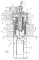
- the regenerator burner shown in the drawing is used to heat a furnace chamber 1, which is in the Cutout furnace wall 2 is limited, the one has continuous cylindrical opening 3.
- a ceramic jacket radiant tube 4 sealed used that protruding into the furnace chamber 1 Part is closed at 5 and the end molded ring flanges 6 and intermediate layers 7 against the Outside of the furnace wall 2 is supported.
- a coaxial burner head 8 is placed on the furnace wall 2, the steel housing 9 inside with heat-insulating material 10th is lined.
- a fuel distributor sits on the burner head 11 of which in the jacket radiant tube 4 projecting and coaxial to this fuel lance 12, the fuel supply means and the one above at 13 indicated valve fuel, usually natural gas or the like, can be supplied.
- the fuel lance 12 surrounding with a radial distance goes from that Fuel distributor 11, a fuel supply pipe 14 from that is shorter than the fuel lance 12 and over one Valve 15 also with fuel (natural gas or the like) can be applied.
- the fuel supply pipe 14 is made of a thin-walled one Ceramic material existing cylindrical inner tube 16 surrounded in radial distance, which ends sealed in the burner head 8 is used inside.
- the Inner tube 16 is against the fuel supply tube 14 poorly heat conductive, high temperature resistant, ceramic Material thermally insulated, as indicated at 17.
- the inner tube 16 is at a greater radial distance from a coaxial, made of thin-walled ceramic material surround second tube 18, the end at 19 an annular flange 20 is attached, via which it is attached to the Burner head 8 is supported.
- Coaxial to the second ceramic tube 18 is also made of thin-walled ceramic material existing outer cylindrical tube 21 is provided, connected at the end to an annular flange 22 and is held on the burner head 8.
- annular spaces 24, 25 are formed coaxially, radially one inside the other.
- annular spaces 24, 25 are arranged, each of which annular heat storage element 28 contains, which consist of ceramic material and their structure, can also be seen in particular from FIG.
- the annular heat storage elements 28 have axially continuous channels with a clear width of approx. 2 mm. They are divided into sector-shaped ring segments 29 which arranged abutting in the circumferential direction are. This will result in an uncontrolled break thermal stresses avoided. In the axial direction are the annular heat storage elements 28 separated from each other by small spaces 30 which determined by spacers not shown are. In addition, the heat storage elements 28 are each on an edge of the second tube 18 or the outer Supported tube 22, as shown in Figure 1 at 31 or 32 is shown.
- the figure also shows that the two regenerators 26, 27 over a considerable part their axial length overlapping each other within the Furnace wall 2 lie, the radial external regenerator 27 over almost its entire axial length in the outer tube 22 is received, while the radially inner Regenerator 26 is about half in the interior of the burner head 8 extends.
- the outer tube 21 is on the furnace chamber 1 facing Front side at 33 funnel-shaped towards the inside moved in, so that there is one towards the furnace chamber 1 has a tapered conical surface.
- a nozzle ring 34 ( Figure 1, 3) placed in the Folded essentially meandering and on its outer circumferential surface according to the slope of the inner wall of the funnel-shaped indented area 33, is designed.
- the nozzle ring 34 extends in the axial direction up to the second Tube 18 to which he puts on inside, like this Figure 1 can be seen.
- nozzle ring 34 In the nozzle ring 34 is a pot or cap-shaped end cover 35 used on the conical inner wall 36 of the nozzle ring 34 with a corresponding cone angle Circumferential area is supported and in the axial direction protrudes the nozzle ring 34 into the furnace chamber 1.
- the lid 35 has a central opening 37 through which the fuel lance 12 is carried out.
- the cover 35 only about half the axial height of the Nozzle ring 34, approximately up to one below the heat storage elements 28 of the radial outer regenerator 27 lying annular space 38 delimited by the tubes 18, 22.
- the funnel-shaped Area 33 of the outer tube 21 and inside through the Cover 35 limited area of that described in the Way used nozzle ring 34 are meandering in the folded nozzle ring 34 side by side, channel-like Nozzle openings 39, 40 limited in cross section are approximately trapezoidal and with their centers on an imaginary circle coaxial to the fuel lance 12 lie, which is indicated in Figure 3 at 41.
- nozzle openings 39, 40 are thus symmetrical and evenly distributed around the fuel lance 12 arranged.
- the nozzle openings 39 open into the Annulus 38 of the radially outer regenerator 27 while the adjacent nozzle openings 40 into a the fuel lance 12 lead coaxial combustion chamber 42, the limited by the tube 18, the nozzle ring 34 and the cover 35 is.
- the fuel supply pipe 14 which along with one the fuel lance 12 arranged baffle 43, a nozzle-like fuel outlet limited.
- the fuel lance passed through the combustion chamber 42 12 lying leads an ignition electrode into the combustion chamber 42 44 with assigned ionization monitoring, their assigned electrical connection device on the fuel distributor 11 sits and is designated 45.
- a coaxial ceramic flame tube 46 is arranged fixed by thin webs, as indicated at 47 is held.
- annular spaces 48, 25 separated axially from one another, of which the annular space 48 with the radially inner Regenerator 26 and the annular space 25 with the radial external regenerator 27 are connected.
- annular space 48 with the radially inner Regenerator 26 and the annular space 25 with the radial external regenerator 27 are connected.
- the via a changeover valve device 52 optionally with a Combustion air supply duct 53 or with a combustion exhaust duct 54 can be connected.
- regenerator burner basically works in EP 0 463 218 A3 and EP 0 685 683 A3 described by the applicant:
- the first step is Start operation of the furnace chamber 42 via the fuel supply pipe 14 and the radially inner regenerator 26 Fuel and combustion air supplied.
- the air / fuel mixture is ignited by the ignition electrode 44 and burned.
- the hot combustion gases pass through the Nozzle openings 39 into the jacket radiant tube 4, paint over the inner wall and are over the Nozzle openings 40, the annular space 38, the radially outer Regenerator 26 and the combustion gas discharge 54 dissipated.
- the ignition temperature approximately equal to the fuel supply pipe 14 the fuel lance opening outside the combustion chamber 42 12 unswitched (valves 13/15).
- the one from the fuel lance 12 escaping fuel (usually gas) is in the flame tube 46 and in the between these and the as Air cone for those emerging from the nozzle openings 39 Air jet acting cover 35 lying area oxidized, at the same time intensive mixing with by the impulse effect of the nozzle openings 39 escaping, intensely circulated hot exhaust gases he follows.
- the through the heat emission through the jacket radiant tube 4 Flue gases cooled in the furnace chamber 1 flow via the nozzle openings 40 acting as outlet nozzles, through the radially outer regenerator 27 and the Combustion gas exhaust line 54, the ceramic Heat storage elements 28 of this regenerator heated become.
- regenerator 27 As soon as the regenerator 27 is fully heated, switches the valve device 52 around, with the result that the Combustion air now flows through the hot regenerator 27 and is preheated while the hot combustion gases via the nozzle openings now acting as inlet nozzles 39 and the combustion chamber 42 the radially inner Flow through regenerator 26 and its ceramic Heat up heat storage elements 28.
- the nozzle openings 39, 40 of the nozzle ring 34 work thus intermittently as inlet and outlet nozzles, like this in Figure 1 is indicated by arrows, of which the arrows 55 the alternating flow through the nozzle openings 39 and the arrows 56 the alternate flow of the Illustrate nozzle openings 40.
- the generator burner shown in Figure 1 works with a jacket radiant tube 4 closed at the end, this as well as the flame tube 46 and the tubes 16, 18, 22 and the nozzle ring 34 and the cover 35 made of a thin-walled Ceramic material with a wall thickness of Rule 2 to 5 mm exist. Basically, the generator burner but also for direct heating of the furnace chamber 1 are used, the jacket radiant tube 4 then eliminated. Otherwise the arrangement basically remains as shown in Figure 1.
- regenererator 27 used during start-up become.
- the annular space 38 used as an annular combustion chamber which is why it is used with a (not further illustrated) fuel supply device and an ignition device is equipped.
Landscapes
- Engineering & Computer Science (AREA)
- Chemical & Material Sciences (AREA)
- Combustion & Propulsion (AREA)
- Mechanical Engineering (AREA)
- General Engineering & Computer Science (AREA)
- Gas Burners (AREA)
- Combustion Of Fluid Fuel (AREA)
- Air Supply (AREA)
Description
Die Erfindung betrifft einen Regeneratorbrenner, insbesondere zur Beheizung von Ofenräumen von Industrieöfen.The invention relates to a regenerator burner, especially for heating furnace rooms of industrial furnaces.
Unter Regeneratorbrennern sind Industriebrenner verstanden, die mit regenerativer Luftvorwärmung arbeiten und dazu in der Regel mit zwei integrierten Regeneratoren arbeiten, die abwechselnd mit heißen Verbrennungsabgasen und mit kalter Verbrennungsluft im Gegenstrombetrieb beaufschlagt werden. Solche Regeneratorbrenner erlauben es eine höhere Luftvorwärmung als sogenannte RekuperatorBrenner zu erzielen, d.h., Industriebrenner, die einen eingebauten Rekuperator aufweisen. Die bei Regeneratorbrennern erzielbare, relative Luftvorwärmung beträgt bis zu 90%, d.h. bei einer Abgaseintrittstemperatur von bspw. 1000°C kann die Verbrennungsluft auf ca. 900°C vorgewärmt werden. Industrial burners are among regenerative burners understood that work with regenerative air preheating and usually with two integrated regenerators work alternately with hot combustion gases and with cold combustion air in counterflow mode be charged. Such regenerator burners allow it higher air preheating than so-called recuperator burners to achieve, i.e., industrial burners, the one have built-in recuperator. The one with regenerative burners achievable, relative air preheating is up to 90%, i.e. at an exhaust gas inlet temperature of e.g. The combustion air can be preheated to approx. 900 ° C at 1000 ° C become.
Wegen der hohen Luftvorwärmung arbeiten Industriebrenner mit integrierten Regeneratoren mit einem sehr guten Wirkungsgrad: sie erfordern aber in der Regel Maßnahmen zur NOx -Minderung. Ein Beispiel für einen solchen Regeneratorbrenner ist in der EP 0 685 683 A3 des Anmelders beschrieben.Because of the high air preheating, industrial burners work with integrated regenerators with a very good efficiency: However, they generally require measures to reduce NO x . An example of such a regenerator burner is described in the applicant's EP 0 685 683 A3.
Bei diesen Regeneratorbrenner ist in einem die Brennstofflanze koaxial umgebenden Ringraum ein einziger koaxial durchströmter Regenerator vorgesehen, dessen Wärmespeicherelemente aus einzelnen, aufeinander gestapelten, keramischen Regeneratorscheiben bestehen. Dem Regenerator ist eine keramische Brennkammer nachgeschaltet, die über eine im Querschnitt etwa kleeblattförmig gestaltete Düse in die Ofenkammer mündet und in der Gas und Luft bis zum Erreichen der Zünd-Temperatur im Ofenraum (ca. 800°C) verbrannt werden. Danach wird die Gaszufuhr für die Verbrennung im Ofenraum umgeschaltet. Da der Regeneratorbrenner nur mit einem Regenerator ausgerüstet ist, wird er anschliessend absatzweise in zwei Betriebszyklen betrieben. Während eines ersten Betriebszyklus wird sein Regenerator bei abgesperrter Brennstoff- und Verbrennungsluftzufuhr von heißen Ofenabgasen durchströmt, die die Wärmespeicherelemente des Regenerators aufheizen. Sowie der Regenerator aufgeheizt ist wird durch entsprechende Umschaltung von Abgas- und Verbrennungsluftventilen der zweite Betriebszyklus eingeleitet, in dem die Wärmespeicherscheiben des Regenerators im umgekehrten Sinn von der Verbrennungsluft durchströmt werden und damit die Verbrennungsluft vor ihrem Eintritt in die Brennkammer und von da in den Ofenraum vorwärmen. Wegen dieses zyklischen Betriebes sind in der Praxis mindestens zwei Regeneratorbrenner dieser Art erforderlich, die paarweise betrieben, abwechselnd mit Verbrennungsluft und Ofenabgas beaufschlagt werden. In vielen Fällen stört die Anordnung von zwei Brennern nicht, z. B. bei direkter Beheizung oder bei Strahlrohren mit zwei Schenkeln, wie sie ebenfalls in dieser Druckschrift erläutert sind. Eine ähnliche Anordnung mit zwei Generatorbrennern, deren Regeneratoren allerdings außerhalb der Ofenwand liegen, ist aus der EP 0 293 168 A2 bekannt.With this regenerative burner, the fuel lance is in one coaxial surrounding annulus a single coaxial flow through regenerator provided, the heat storage elements from individual, stacked, ceramic Regenerator discs exist. The regenerator is a ceramic combustion chamber downstream, which has a in cross-section approximately cloverleaf-shaped nozzle in the Oven chamber opens and in the gas and air until it is reached the ignition temperature in the furnace chamber (approx. 800 ° C) burned become. Then the gas supply for combustion in the Furnace room switched. Since the regenerator burner only with is equipped with a regenerator, it will then operated batchwise in two operating cycles. While a regenerator will be used in a first operating cycle blocked fuel and combustion air supply from hot furnace exhaust flows through the heat storage elements of the regenerator. As well as the regenerator is heated up by switching over accordingly Exhaust and combustion air valves the second operating cycle initiated in which the heat storage discs of Regenerators in the opposite sense from the combustion air are flowed through and thus the combustion air in front their entry into the combustion chamber and from there into the furnace chamber Preheat. Because of this cyclical operation are in practice at least two regenerator burners of this type required, operated in pairs, alternating with Combustion air and furnace exhaust gas are applied. In in many cases the arrangement of two burners does not bother, z. B. with direct heating or with radiant tubes two legs, as also in this document are explained. A similar arrangement with two generator burners, whose regenerators, however, outside the Oven wall are known from EP 0 293 168 A2.
Bei einem anderen, in der EP 0 463 218 A3 des Anmelders
geoffenbarten Regeneratorbrenner ist die Anordnung
derart getroffen, dass rings um einen die Brennstofflanze
mit radialem Abstand umschliessenden, koaxialen Luftleitzylinder
6 Regeneratorpatronen angeordnet sind, die in der
den Brenner aufnehmenden Öffnung der Ofenwand liegen. Jede
der Regeneratorpatronen besteht aus einer Anzahl strömungsmäßig
hintereinander angeordneter, übereinander
gestapelter keramischer Speichersteine, die durchgehende
Strömungskanäle enthalten. Die Regeneratorpatronen sind
jeweils mit einem die Speichersteine aufnehmenden, rohrförmig
gestalteten Außenmantel aus Stahlblech versehen, an
dem sich auf der dem Ofenraum zugewandten Seite eine
Düsenkammer anschliesst, in deren Bodenwand jeweils zwei
Düsen angeordnet sind. Alle Düsen der Regeneratorpatronen
liegen auf einem zu der Brennstofflanze koaxialen gedachten
Kreis, wobei benachbarte Düsen einen gleichen Achsabstand
aufweisen. Die Düsenkammern der Regeneratorpatronen
umschliessen eine an den Luftleitzylinder angeschlossene
keramische Brennkammer, in die die Brennstofflanze
mündet. Die Brennkammer erlaubt es im Ofenraum die notwendige
Zünd-Temperatur von ca. 800°C zu erzielen. Die Regeneratorpatronen
werden gruppenweise in einem von zwei
Betriebszyklen betrieben, von denen in dem einen sie von
den heißen Verbrennungsabgasen durchströmt und aufgeheizt
werden, während sie in dem anderen die gespeicherte Wärme
an die sie durchströmende, kalte Verbrennungsluft abgeben.
Zwischen den zylindrischen Regeneratorpatronen verbleibt
ein beträchtliches, ungenutztes Zwickelvolumen, so dass
das Wärmespeichervermögen der Regeneratoren begrenzt ist.Another, in the applicant's EP 0 463 218 A3
The disclosed regenerator burner is the arrangement
hit in such a way that the fuel lance surrounds you
with a radial spacing, coaxial
Grundsätzlich Ähnliches gilt schliesslich noch für einen aus der EP 0 715 123 A2 bekannten Regeneratorbrenner, bei dem die beiden innerhalb eines zu der zentralen Brennstofflanze koaxialen Rohres angeordneten Regeneratoren in einer Ausführungsform von einer Anzahl mit ihren Achsen auf einem gemeinsamen gedachten Kreis liegender Regeneratorpatronen gebildet und in einer anderen Ausführungsform in einem zu der Brennstofflanze koaxialen Ringraum angeordnet sind, der durch radiale Trennwände abgeteilt ist. Die sektorförmigen Abteilungen enthalten die bspw. als keramische Wabensteine vorliegenden, übereinander gestapelten Wärmespeicherelemente. Die abwechselnde Beaufschlagung der beiden so gebildeten Regeneratoren mit heißen Verbrennungsabgasen oder kalter Verbrennungsluft erfolgt durch eine Ventileinrichtung, die zwei gegeneinander verdrehbare Lochscheiben aufweist. Während für die Ausführungsform mit den kranzförmig angeordneten Regeneratorpatronen das oben bezüglich des Zwickelvolumens Gesagte gilt, ist die zweite Ausführungsform in der Herstellung kompliziert, wenn das die Wärmespeicherelemente aufnehmende zylindrische Rohr und die in dieses eingesetzten radialen Trennwände aus Keramikmaterial hergestellt werden sollen. U.a. treten Abdichtungsprobleme auf.Basically, the same applies to a regenerator burner known from EP 0 715 123 A2, where the two are within one to the central Fuel lance coaxial tube arranged regenerators in one embodiment of a number with their Axes lying on a common imaginary circle Regenerator cartridges formed and in another embodiment in a coaxial to the fuel lance Annulus are arranged by radial partitions is divided. The sector-shaped departments included the present as ceramic honeycomb stones, one above the other stacked heat storage elements. The alternate Actuation of the two regenerators thus formed with hot combustion gases or cold combustion air is done by a valve device, the two has perforated disks rotatable relative to one another. While for the embodiment with the wreath-shaped arrangement Regenerator cartridges the above regarding gusset volume Said applies, is the second embodiment in the manufacture complicated if that's the heat storage elements receiving cylindrical tube and the inserted in this radial partitions made of ceramic material should be. Et al there are sealing problems.
Ausgehend von diesem Stand der Technik liegt der Erfindung die Aufgabe zugrunde, einen Industriebrenner mit regenerativer Luftvorwärmung, d.h. einen sogenannten Regeneratorbrenner zu schaffen, der sich bei einfachem Aufbau mit innerhalb eines zylindrischen, äußeren Rohres angeordneten Regeneratoren durch ein hohes Wärmespeichervermögen auszeichnet und aufgrund seiner Konstruktion auch dazu geeignet ist, mit geringer NOx -Emmission betrieben werden zu können.Based on this prior art, the invention has for its object to provide an industrial burner with regenerative air preheating, i.e. a so-called regenerator burner, which is characterized by a high heat storage capacity and due to its design also simple construction with regenerators arranged within a cylindrical outer tube is suitable for being able to be operated with low NO x emissions.
Zur Lösung dieser Aufgabe ist der Generatorbrenner erfindungsgemäß durch die Merkmale des Patentanspruch 1 gekennzeichnet.The generator burner is used to solve this task According to the invention by the features of claim 1 characterized.
Bei dem neuen Generatorbrenner sind die beiden Regeneratoren konzentrisch in zwei die Brennstoffzuführmittel umgebenden Ringräumen angeordnet, die zumindest über einen Teil ihrer axialen Länge radial ineinanderliegend in einem sie umgebenden äußeren, zylindrischen Rohr angeordnet sind. Die Verbrennungsluft und das Verbrennungsabgas werden, wie üblich, periodisch auf die beiden Regeneratoren umgeschaltet. Das Umschaltventil zur periodischen Umsteuerung von Verbrennungsluft und Verbrennungsabgas befindet sich in der Regel direkt am Brennerkopf.The two regenerators are in the new generator burner concentric in two the fuel supply means surrounding annular spaces arranged at least over a Part of its axial length lying radially one inside the other surrounding outer cylindrical tube arranged are. The combustion air and the combustion exhaust gas are, as usual, periodically on the two regenerators switched. The switching valve for periodic Reversal of combustion air and combustion exhaust gas is usually located directly on the burner head.
An dem dem Brennerkopf gegenüberliegenden Ende sind den beiden die Regeneratoren aufnehmenden Ringräumen Düsenmittel zugeordnet, die abwechselnd als Ein- und Auslassdüsen betreibbar sind. Diese weisen eine Anzahl ringförmig verteilt angeordneter Düsenöffnungen auf, die mit ihren Mittelachsen, zumindest annähernd, auf einem zu dem Brennstoffzuführmitteln konzentrischen, gedachten Kreis liegen und die, gegebenenfalls gruppenweise, mit den Wärmespeicherelementen des einen oder des anderen Regenerators in Verbindung stehen. Sie können in einer bevorzugten Ausführungsform durch einen im Wesentlichen mäanderförmig geformten Düsenring begrenzt sein, der mit einem koaxialen Rohr wenigstens eines der beiden Regeneratoren verbunden ist.At the end opposite the burner head the two annular spaces accommodating the regenerators Assigned nozzle means, which alternate as one and Outlet nozzles are operable. These have a number annularly distributed nozzle openings on the with their central axes, at least approximately, towards one concentric to the fuel supply means Circle and which, if necessary in groups, with the Heat storage elements of one or the other regenerator stay in contact. You can in a preferred Embodiment by a substantially meandering shaped nozzle ring may be limited to that with a coaxial tube at least one of the two regenerators connected is.
Zwischen den Düsenmitteln und wenigstens dem radial innenliegenden Regenerator ist zweckmäßigerwese eine Brennkammer angeordnet, in die eine Brennstoffzufuhreinrichtung, insbesondere für den Startbetrieb führt. Im Aufheizbetrieb, unter etwa 800°C, wird das Verbrennungsgas der Brennkammer zugeführt, während der zugehörige Regenerator mit Verbrennungsluft beaufschlagt wird. Das bedeutet zwar eine Halbierung der Leistung in der Zeit während der die Ofenkammer auf Betriebstemperatur gebracht wird. In der Praxis ist dies jedoch in vielen Fällen zulässig. Erforderlichenfalls kann aber auch der äußere Regenerator mit einer Ringbrennkammer und eigener Verbrennungsgaszufuhr ausgestattet werden, womit erreicht wird, dass während der Aufheizphase die volle Leistung zur Verfügung steht. Allerdings wird damit auch eine zweite Zünd- und Überwachungseinrichtung notwendig, was einen gewissen Aufwand bedeutet.Between the nozzle means and at least that radially internal regenerator is expediently one Combustion chamber arranged in which a fuel supply device, leads especially for the start operation. in the Heating mode, below about 800 ° C, the combustion gas fed to the combustion chamber while the associated regenerator is supplied with combustion air. That means while halving performance in time during the the furnace chamber is brought to operating temperature. In in practice, however, this is permissible in many cases. If necessary, the outer regenerator can also with an annular combustion chamber and its own combustion gas supply what is achieved during full power is available during the heating phase stands. However, it also becomes a second ignition and Monitoring device necessary, what a certain Effort means.
Ein wesentlicher weiterer Vorteil der konzentrischen Anordnung der beiden Regeneratoren besteht in der Möglichkeit die die keramischen Wärmespeicherelemte aufnehmenden Rohre, die Brennkammer, die Düsenmittel und andere hohen Temperaturen ausgesetzte Teile aus hochtemperaturfestem, dünnwandigem Keramikmaterial (Schlickerguss) herzustellen. Enthalten die Düsenmittel den oben erwähnten, im Wesentlichen mäanderförmig geformten Düsenring, so kann dieser in einfacher Weise aus dünnwandigem Keramikmaterial hergestellt und einfach durch Einstecken in das zugeordnete koaxiale Rohr montiert werden, wobei in ihn ein die Düsenöffnungen radial nach innen zu begrenzendes Deckelteil eingesetzt werden kann. Durch die abwechselnde und symmetrische Anordnung der Ein-/Auslass-Düsenöffnungen beider Regeneratoren zum Ofenraum hin auf einem Kreisring um die zentralen Brennstoffzuführmittel (bspw. Gaslanze) wird eine gute Rezirkulation der Verbrennungsgase im Ofenraum bzw. in einem Strahlrohr erreicht.Another essential advantage of concentric Arrangement of the two regenerators is possible the receiving the ceramic heat storage elements Pipes, the combustion chamber, the nozzle means and other high Parts exposed to high temperature resistant, to produce thin-walled ceramic material (slip casting). The nozzle means essentially contain those mentioned above meandering shaped nozzle ring, this can in simply made from thin-walled ceramic material and simply by plugging in the assigned one coaxial tube to be mounted, with the nozzle openings in it cover part to be defined radially inwards can be used. Due to the alternating and symmetrical Arrangement of the inlet / outlet nozzle openings of both Regenerators towards the furnace on a circular ring around the central fuel supply means (e.g. gas lance) good recirculation of the combustion gases in the furnace chamber or reached in a jet pipe.
Der neue Generatorbrenner ist insbesondere zur Verwendung mit einem endseitig verschlossenen einschenkeligen Mantelrohr, einem sogenannten Mantelstrahlheizrohr geeignet. Er kann aber auch zur Direktbeheizung eines Ofenraumes eingesetzt werden. In diesem Falle ist die Anordnung derart getroffen, das bei in eine entsprechende Öffnung der Wand des Ofenraumes eingesetztem Regeneratorbrenner die im Bereiche der innenliegende Wandseite befindlichen Düsenmittel frei in den Ofenraum mündend.The new generator burner is particularly suitable for use with one leg closed at the end Jacket tube, a so-called jacket jet heating tube suitable. But it can also be used for the direct heating of an oven room be used. In this case the order is taken in such a way that in a corresponding Opening of the wall of the furnace chamber inserted regenerator burner that in the area of the inner wall side nozzle means located freely into the furnace chamber.
Die beiden Regeneratoren des neuen Regeneratorbrenners enthalten mit Vorteil ringförmige Wärmespeicherelemente, die axial durchströmbare Kanäle enthalten. Um einen unkontrollierten Bruch durch unterschiedliche Wärmedehnung, etc. zu vermeiden, ist es zweckmäßig, wenn die ringförmigen Wärmespeicherelemente in sektorförmige Ringsegmente aufgeteilt sind, die nebeneinander liegend angeordnet sind.The two regenerators of the new regenerator burner advantageously contain ring-shaped heat storage elements, contain axially flowable channels. To one uncontrolled breakage due to different thermal expansion, etc. to avoid, it is useful if the annular heat storage elements in sector-shaped ring segments are divided, which are arranged side by side are.
Andere Weiterbildungen des neuen Generatorbrenners sind Gegenstand von Unteransprüchen.Other developments of the new generator burner are the subject of subclaims.
In der Zeichnung ist ein Ausführungsbeispiel des Gegenstandes der Erfindung dargestellt. Es zeigen:
- Figur 1
- einen Generatorbrenner, gemäß der Erfindung im axialen Schnitt, längs der Linie I-I der Figur 3 in einer Seitenansicht und in schematischer Darstellung,
Figur 2- den Regeneratorbrenner nach Figur 1, geschnitten längs der Linie II-II der Figur 1, in einer Draufsicht und
- Figur 3
- den Regeneratorbrenner nach Figur 1, geschnitten längs der Linie III-III der Figur 1 in einer Draufsicht.
- Figure 1
- a generator burner, according to the invention in axial section, along the line II of Figure 3 in a side view and in a schematic representation,
- Figure 2
- the regenerator burner of Figure 1, cut along the line II-II of Figure 1, in a plan view and
- Figure 3
- the regenerator burner of Figure 1, cut along the line III-III of Figure 1 in a plan view.
Der in der Zeichnung dargestellte Regeneratorbrenner
dient zur Beheizung eines Ofenraumes 1, der durch eine im
Ausschnitt dargestellte Ofenwand 2 begrenzt ist, die eine
durchgehende zylindrische öffnung 3 aufweist. In die
Öffnung 3 ist ein keramisches Mantelstrahlheizrohr 4 abgedichtet
eingesetzt, das an seinem in den Ofenraum 1 ragenden
Teil endseitig bei 5 verschlossen ist und das über
angeformte Ringflansche 6 und Zwischenlagen 7 gegen die
Außenseite der Ofenwand 2 abgestützt ist.The regenerator burner shown in the drawing
is used to heat a furnace chamber 1, which is in the
Auf das Mantelstrahlheizrohr 4 ist auf der Außenseite
der Ofenwand 2 ein koaxialer Brennerkopf 8 aufgesetzt,
dessen Stahlgehäuse 9 innen mit wärmedämmenden Material 10
ausgekleidet ist. Auf dem Brennerkopf sitzt ein Brennstoffverteiler
11 von dem eine in das Mantelstrahlheizrohr
4 ragende und zu diesem koaxiale Brennstofflanze 12 abgeht,
die Brennstoffzuführmittel bildet und der über ein
bei 13 angedeutetes Ventil Brennstoff, in der Regel Erdgas
oder dergleichen, zugeführt werden kann. Die Brennstofflanze
12 mit radialem Abstand umgebend, geht von dem
Brennstoffverteiler 11, ein Brennstoffzufuhrrohr 14 ab,
dass kürzer als die Brennstofflanze 12 ist und über ein
Ventil 15 ebenfalls mit Brennstoff (Erdgas oder dergleichen)
beaufschlagt werden kann.On the jacket radiant tube 4 is on the outside
a
Das Brennstoffzufuhrrohr 14 ist von einem aus dünnwandigem
Keramikmaterial bestehenden zylindrischen Innenrohr
16 im radialen Abstand umgeben, welches einenends
abgedichtet in den Brennerkopf 8 innen eingesetzt ist. Das
Innenrohr 16 ist gegen das Brennstoffzufuhrrohr 14 durch
schlecht wärmeleitendes, hochtemperaturfestes, keramisches
Material wärmeisoliert, wie das bei 17 angedeutet ist.The
Das Innenrohr 16 ist in größerem radialem Abstand von
einem koaxialen, aus dünnwandigem Keramikmaterial bestehenden
zweiten Rohr 18 umgeben, das bei 19 endseitig an
einem Ringflansch 20 befestigt ist, über den es an dem
Brennerkopf 8 gehaltert ist. Koaxial zu dem zweiten Keramikrohr
18 ist ein ebenfalls aus dünnwandigem Keramikmaterial
bestehendes äußeres, zylindrisches Rohr 21 vorgesehen,
das endseitig mit einem Ringflansch 22 verbunden und
über diesen an dem Brennerkopf 8 gehaltert ist.The
Zwischen dem inneren Rohr 16, dem dazu koaxialen
zweiten Rohr 18 und dem äußeren Rohr 21, das, wie aus
Figur 1 zu ersehen, im radialen Abstand von dem Mantelstrahlheizrohr
4 verläuft, sind zwei konzentrische Ringräume
24, 25 begrenzt, die zu der Brennstofflanze 12
koaxial, radial ineinanderliegend ausgebildet sind. In den
Ringräumen 24, 25 sind zwei Regeneratoren 26, 27 angeordnet,
von denen jeder ringförmige Wärmespeicherelement 28
enthält, die aus Keramikmaterial bestehen und deren Aufbau,
insbesondere auch aus Figur 2 zu ersehen ist.Between the
Die ringförmigen Wärmespeicherelemente 28 weisen
axial durchgehende Kanäle von ca. 2 mm lichter Weite auf.
Sie sind in sektorförmige Ringsegemente 29 unterteilt, die
in Umfangsrichtung stumpf aneinanderstoßend angeordnet
sind. Dadurch wird ein unkontrollierter Bruch, herrührend
von thermisch bedingten Spannungen, vermieden. In Achsrichtung
sind die ringförmigen Wärmespeicherelemente 28
durch kleine Zwischenräume 30 voneinander getrennt, die
durch nicht weiter dargestellte Abstandsstücke bestimmt
sind. Außerdem sind die Wärmespeicherelemente 28 jeweils
auf einer Randleiste des zweiten Rohres 18 bzw. des äußeren
Rohres 22 abgestützt, wie dies in Figur 1 bei 31 bzw.
32 dargestellt ist. Die Figur zeigt außerdem, dass die
beiden Regeneratoren 26, 27 über einen beträchtlichen Teil
ihrer axialen Länge einander überlappend innerhalb der
Ofenwand 2 liegen, wobei der radiale außenliegende Regenerator
27 fast über seine gesamte axiale Länge in dem
äußeren Rohr 22 aufgenommen ist, während der radial innenliegende
Regenerator 26 sich etwa zur Hälfte in den Innenraum
des Brennerkopfes 8 erstreckt.The annular
Das äußere Rohr 21 ist auf der dem Ofenraum 1 zugewandten
Stirnseite bei 33 trichterförmig nach innen zu
eingezogen, so dass es eine zu dem Ofenraum 1 hin sich
verjüngende Kegelmantelfläche aufweist. Auf den trichterförmig
eingezogenen Bereich 33 des äußeren Rohres 22 ist
innen ein Düsenring 34 (Figur 1, 3) aufgesetzt, der im
Wesentlichen mäanderförmig gefaltet und an seiner Außenumfangsfläche
entsprechend der Schräge der Innenwand des
trichterförmig eingezogenen Bereiches 33, gestaltet ist.
Der Düsenring 34 ragt in Achsrichtung bis an das zweite
Rohr 18 heran, an das er sich innen anlegt, wie dies aus
Figur 1 zu ersehen ist. In den Düsenring 34 ist ein topfoder
kappenförmiger Abschlussdeckel 35 eingesetzt, der auf
der keglig ausgebildeten Innenwand 36 des Düsenringes 34
mit einem einen entsprechenden Kegelwinkel aufweisenden
Umfangsbereich abgestützt ist und der in Achsrichtung über
den Düsenring 34 in den Ofenraum 1 vorragt. De Deckel 35
weist eine mittige Öffnung 37 auf, durch die die Brennstofflanze
12 durchgeführt ist.The
In Achsrichtung der Brennstofflanze 12 erstreckt sich
der Deckel 35 lediglich ca. über die halbe axiale Höhe des
Düsenringes 34, etwa bis zu einem unterhalb der Wärmespeicherelemente
28 des radialen äußeren Regenerators 27
liegenden, von den Rohren 18, 22 begrenzten Ringraums 38.
Durch den außen durch den trichterförmig eingezogenen
Bereich 33 des äußeren Rohres 21 und innen durch den
Deckel 35 begrenzten Bereich des in der geschilderten
Weise eingesetzten Düsenringes 34, sind in dem mäanderförmig
gefalteten Düsenring 34 nebeneinanderliegende, kanalartige
Düsenöffnungen 39, 40 begrenzt, die im Querschnitt
etwa trapezförmig sind und mit ihren Mittelpunkten auf
einem gedachten, zu der Brennstofflanze 12 koaxialen Kreis
liegen, der in Figur 3 bei 41 angedeutet ist. Die mit
ihren Achsen schräg, radial nach innen, zu dem Ofenraum 1
hin gerichteten Düsenöffnungen 39, 40 sind somit symmetrisch
und gleichmäßig verteilt rings um die Brennstofflanze
12 angeordnet. Die Düsenöffungen 39 münden in den
Ringraum 38 des radial außenliegenden Regenerators 27
während die daneben liegenden Düsenöffnungen 40 in eine zu
der Brennstofflanze 12 koaxiale Brennkammer 42 führen, die
von dem Rohr 18, dem Düsenring 34 und dem Deckel 35 begrenzt
ist. In der Brennkammer 42 mündet, in dem Bereich
unmittelbar unter dem radial innenliegenden Regenerator 26
das Brennstoffzufuhrrohr 14, das zusammen mit einer auf
der Brennstofflanze 12 angeordneten Prallscheibe 43, einen
düsenartigen Brennstoffauslass begrenzt. Seitlich der
durch die Brennkammer 42 hindurchgeführten Brennstofflanze
12 liegend, führt in die Brennkammer 42 eine Zündelektrode
44 mit zugeordneter Ionisationsüberwachung, deren zugeordnete
elektrische Anschlußeinrichtung auf dem Brennstoffverteiler
11 sitzt und mit 45 bezeichnet ist.Extends in the axial direction of the
Im axialen Abstand von der Mündung der Brennstofflanze
12 und dem Deckel 35 ist in dem Mantelstrahlheizrohr
4 ein koaxiales keramisches Flammrohr 46 angeordnet, das
durch dünne Stege, wie sie bei 47 angedeutet sind, ortsfest
gehalten ist.At an axial distance from the mouth of the
In dem Brennerkopf 8 sind zwei durch den Ringflansch
20 axial voneinander getrennte Ringräume 48, 25 ausgebildet,
von denen der Ringraum 48 mit dem radial innenliegenden
Regenerator 26 und der Ringraum 25 mit dem radial
außenliegenden Regenerator 27 in Verbindung stehen. In die
Ringräume 48, 25 münden Ein-/Auslass-Kanäle 50, 51, die
über eine Umschaltventileinrichtung 52 wahlweise mit einem
Verbrennungsluftzufuhrkanal 53 oder mit einem Verbrennungsabgaskanal
54 verbunden werden können.In the
Der beschriebene Regneratorbrenner arbeitet grundsätzlich in der in der EP 0 463 218 A3 bzw. der EP 0 685 683 A3 des Anmelders beschriebenen Weise:The regenerator burner described basically works in EP 0 463 218 A3 and EP 0 685 683 A3 described by the applicant:
Ausgehend vom kalten Ruhezustand wird zunächst im
Startbetrieb der Ofenkammer 42 über das Brennstoffzufuhrrohr
14 und den radial innenliegenden Regenerator 26
Brennstoff und Verbrennungsluft zugeführt. Das Luft/Brennstoffgemisch
wird durch die Zündelektrode 44 gezündet und
verbrannt. Die heissen Verbrennungsabgase treten durch die
Düsenöffnungen 39 in das Mantelstrahlheizrohr 4 ein,
überstreichen dessen Innenwandung und werden über die
Düsenöffnungen 40, den Ringraum 38, den radial außenliegenden
Regenerator 26 und die Verbrennungsgasableitung 54
abgeführt. Sowie in dem Mantelstrahlheizrohr 4 die Zündtemperatur
(ca. 800°C ) erreicht ist, wird die Brennstoffzufuhr
über das Brennstoffzufuhrrohr 14 abgesperrt und auf
die außerhalb der Brennkammer 42 mündende Brennstofflanze
12 ungeschaltet (Ventile 13/15). Der aus der Brennstofflanze
12 austretende Brennstoff (in der Regel Gas) wird in
dem Flammrohr 46 und in dem zwischen diesen und dem als
Luftleitkegel für die aus den Düsenöffnungen 39 austretenden
Luftstrahlen wirkenden Deckel 35 liegenden Bereich
oxidiert, wobei gleichzeitig eine intensive Durchmischung
mit den durch die Impulswirkung der aus den Düsenöffnungen
39 autretenden, intensiv umgewälzten heissen Abgasen
erfolgt. Die durch die Wärmeabgabe über das Mantelstrahlheizrohr
4 in den Ofenraum 1 abgekühlten Abgase strömen
über die als Auslassdüsen wirkenden Düsenöffnungen 40,
durch den radial außen liegenden Regenerator 27 und die
Verbrennungsgasabgasleitung 54 ab, wobei die keramischen
Wärmespeicherelemente 28 dieses Regenerators aufgeheizt
werden.Starting from the cold idle state, the first step is
Start operation of the
Sobald der Regenerator 27 voll aufgeheizt ist, schaltet
die Ventileinrichtung 52 um, mit der Folge, dass die
Verbrennungsluft nunmehr den heissen Regenerator 27 durchströmt
und vorgewärmt wird, während die heissen Verbrennungsgase
über die jetzt als Einlassdüsen wirkenden Düsenöffnungen
39 und die Brennkammer 42 den radial innenliegenden
Regenerator 26 durchströmen und dessen keramische
Wärmespeicherelemente 28 aufheizen.As soon as the
Die Düsenöffnungen 39, 40 des Düsenringes 34 arbeiten
somit taktweise als Ein- und Auslassdüsen, wie dies in
Figur 1 durch Pfeile angedeutet ist, von denen die Pfeile
55 die wechselweise Durchströmung der Düsenöffnungen 39
und die Pfeile 56 die wechselweise Durchströmung der
Düsenöffnungen 40 veranschaulichen.The
Der in Figur 1 dargestellte Generatorbrenner arbeitet
mit einem endseitig verschlossenen Mantelstrahlheizrohr 4,
das ebenso wie das Flammrohr 46 und die Rohre 16, 18, 22
sowie der Düsenring 34 und der Deckel 35 aus einem dünnwandigen
Keramikmaterial mit einer Wandstärke von in der
Regel 2 bis 5 mm bestehen. Grundsätzlich kann der Generatorbrenner
aber auch zum direkten Beheizen des Ofenraums 1
eingesetzt werden, wobei das Mantelstrahlheizrohr 4 dann
entfällt. Ansonsten bleibt die Anordnung grundsätzlich so,
wie in Figur 1 dargestellt.The generator burner shown in Figure 1 works
with a jacket radiant tube 4 closed at the end,
this as well as the
In dem erläuterten Startbetrieb, in dem über das
Brennstoffzufuhrrohr 14 Brennstoff in die Brennkammer 42
eingebracht und diese lediglich über den radial innenliegenden
Regenerator 26 mit Verbrennungsluft beaufschlagt
wird, arbeitet der Regeneratorbrenner bei der dargestellten
Ausführungsform nur mit halber Leistung. Dies ist in
der Regel kein Nachteil.In the explained start operation, in which the
Falls erforderlich, kann aber auch der radial außenliegende
Regenerator 27 während des Startbetriebes eingesetzt
werden. Zu diesem Zwecke wird dann der Ringraum 38
als Ringbrennkammer benutzt, wozu sie mit einer (nicht
weiter dargestellten) Brennstoffzufuhreinrichtung und
einer Zündeinrichtung ausgestattet wird.If necessary, the radially external one can also be used
Claims (12)
- Regenerator burner, in particular for heating furnace chambers of industrial furnaces, having
an outer tube (21) with coaxial central fuel feed means (12) arranged therein,
a gas port end (8) which comprises combustion air supply and combustion gas exhaust means (25, 48, 51, 50) and from which the outer tube (21) departs,
two regenerators (26, 27) that can be alternately supplied with combustion air and combustion exhaust gases, respectively,
the two regenerators (26, 27) being arranged in two annular chambers (24, 25), which are coaxially arranged with respect to the fuel feed means (12) and which, enclosing the latter and extending at least over part of their axial length in the outer tube, are arranged radially one inside the other, and
having further, at the end opposite the gas port end (8), nozzle means (34; 39, 40) that are associated to the two annular chambers (24, 25) and can be operated alternately as inlet and outlet nozzles, respectively. - The regenerator burner as defined in Claim 1, characterised in that each of the two regenerators (26, 27) comprises annual heat accumulator elements (28) through which a flow can pass in axial direction.
- The regenerator burner as defined in Claim 2, characterised in that the annular heat accumulator elements (28) are subdivided into sector-shaped annular segments (29).
- The regenerator burner as defined in any of the preceding claims, characterised in that when the regenerator burner is fitted in a corresponding opening (3) of a wall (2) of a furnace chamber (1), the regenerators (26, 27) are located, at least partially, in the region of the furnace wall (2).
- The regenerator burner as defined in any of the preceding claims, characterised in that the nozzle means comprise a number of nozzle openings (39, 40) distributed in an annular pattern, the centre axes of which lie at least approximately on an imaginary circle (41) drawn concentrically relative to the fuel feed means (12) and which are connected alternately - in groups, if desired - with the heat accumulator elements (28) of the one or the other regenerator (26, 27).
- The regenerator burner as defined in Claim 5, characterised in that the nozzle openings (39, 40) are defined by a substantially meander-shaped nozzle ring (34) connected with a coaxial tube (21) of at least one of the two regenerators (26, 27).
- The regenerator burner as defined in Claim 6, characterised in that a cover element (35) delimiting the nozzle openings radially toward the inside is fitted in the nozzle ring (34).
- The regenerator burner as defined in any of the preceding claims, characterised in that a burner chamber (42) is arranged between the nozzle means (34; 39, 40) and at least the radially inner regenerator (26)m with fuel feed means (14), intended especially to support the starting operation, leading into that chamber.
- The regenerator burner as defined in any of the preceding claims, characterised in that at least tubes (16, 18, 21) accommodating the nozzle means (34) and the ceramic accumulator elements (28) of the regenerators (26, 27) are made from a thin-walled ceramic material.
- The regenerator burner as defined in any of the preceding claims, characterised in that when the regenerator burner is fitted in a corresponding opening (3) of a wall (2) of a furnace chamber (1), the nozzle means (34; 39, 40) present in the region of the inner wall surface are arranged to project freely into the furnace chamber (1).
- The regenerator burner as defined in any of claims 1 to 7, characterised in that it comprises a jacket-type radiant tube (4), closed on its one end, into which open the nozzle means (34; 39, 40).
- The regenerator burner as defined in Claim 11, characterised in that the jacket-type radiant tube (4) consists of a thin-walled ceramic material.
Applications Claiming Priority (2)
| Application Number | Priority Date | Filing Date | Title |
|---|---|---|---|
| DE19740788 | 1997-09-17 | ||
| DE19740788A DE19740788C1 (en) | 1997-09-17 | 1997-09-17 | High-temperature industrial regenerative burner assembly |
Publications (3)
| Publication Number | Publication Date |
|---|---|
| EP0903539A2 EP0903539A2 (en) | 1999-03-24 |
| EP0903539A3 EP0903539A3 (en) | 1999-09-15 |
| EP0903539B1 true EP0903539B1 (en) | 2003-05-14 |
Family
ID=7842571
Family Applications (1)
| Application Number | Title | Priority Date | Filing Date |
|---|---|---|---|
| EP98115221A Expired - Lifetime EP0903539B1 (en) | 1997-09-17 | 1998-08-13 | Regenerator burner |
Country Status (4)
| Country | Link |
|---|---|
| EP (1) | EP0903539B1 (en) |
| JP (1) | JPH11148605A (en) |
| KR (1) | KR19990029822A (en) |
| DE (2) | DE19740788C1 (en) |
Cited By (1)
| Publication number | Priority date | Publication date | Assignee | Title |
|---|---|---|---|---|
| RU2656220C1 (en) * | 2013-11-20 | 2018-06-01 | ТЕНОВА С.п.А. | Self-regenerating industrial burner and industrial furnace for carrying out self-regenerating combustion processes |
Families Citing this family (11)
| Publication number | Priority date | Publication date | Assignee | Title |
|---|---|---|---|---|
| KR100332694B1 (en) * | 1999-09-13 | 2002-04-17 | 손재익 | A regenerative and radiant gas burner having a device for converting air passageway |
| EP1101924A1 (en) | 1999-11-16 | 2001-05-23 | BHKW Betreiber GmbH & Co. Anlagen KG | Energy converter and method of operating such a converter |
| KR100481369B1 (en) * | 2000-03-13 | 2005-04-07 | 주식회사 포스코 | Regenerative burner |
| ITMI20032327A1 (en) * | 2003-11-28 | 2005-05-29 | Techint Spa | GAS BURNER WITH LOW POLLUTING EMISSIONS. |
| CZ302827B6 (en) * | 2005-06-14 | 2011-11-30 | Kalousek@Zdenek | Regenerative burner system |
| EP1995515B1 (en) * | 2007-05-23 | 2013-10-30 | WS-Wärmeprozesstechnik GmbH | Supported FLOX operation and burner therefor |
| ITMI20112380A1 (en) * | 2011-12-23 | 2013-06-24 | Danieli Off Mecc | SELF-REGENERATING COMBUSTION SYSTEM WITH LOW NOX EMISSIONS |
| CN102563654A (en) * | 2012-02-25 | 2012-07-11 | 佛山市科皓燃烧设备制造有限公司 | Self-heat storage type gas burner |
| CN104109753A (en) * | 2014-07-15 | 2014-10-22 | 河北钢铁股份有限公司唐山分公司 | Single air regenerative burner for roller hearth furnace |
| EP3032171B1 (en) | 2014-12-09 | 2018-01-31 | WS-Wärmeprozesstechnik GmbH | Regenerativ heated radiant tube |
| US20210131662A1 (en) * | 2019-10-30 | 2021-05-06 | Honeywell International Inc. | Recuperative gas burner for industrial applications and method of operating the same |
Family Cites Families (8)
| Publication number | Priority date | Publication date | Assignee | Title |
|---|---|---|---|---|
| GB540797A (en) * | 1940-04-29 | 1941-10-30 | Howden James & Co Ltd | Improvements in or relating to air preheaters for use with boiler plant |
| US2795213A (en) * | 1954-12-30 | 1957-06-11 | Air Preheater | Zoned air heater |
| JPH0623605B2 (en) * | 1987-05-26 | 1994-03-30 | 日本ファーネス工業株式会社 | Radiant tube burner |
| ES2064538T3 (en) * | 1990-06-29 | 1995-02-01 | Wuenning Joachim | PROCEDURE AND DEVICE FOR COMBUSTION OF FUEL IN A COMBUSTION ENCLOSURE. |
| WO1995015462A1 (en) * | 1993-12-03 | 1995-06-08 | Nippon Furnace Kogyo Kabushiki Kaisha | Regenerative type burner and storage type heat exchanging system available therefor |
| DE4419332A1 (en) * | 1994-06-02 | 1995-12-14 | Wuenning Joachim | Industrial burner with low NO¶x¶ emissions |
| DE4420477C2 (en) * | 1994-06-11 | 2000-05-04 | Ws Waermeprozestechnik Gmbh | Industrial burner with regenerative air preheating |
| TW278124B (en) * | 1994-10-14 | 1996-06-11 | Toyota Motor Co Ltd |
-
1997
- 1997-09-17 DE DE19740788A patent/DE19740788C1/en not_active Expired - Fee Related
-
1998
- 1998-08-13 EP EP98115221A patent/EP0903539B1/en not_active Expired - Lifetime
- 1998-08-13 DE DE59808336T patent/DE59808336D1/en not_active Expired - Lifetime
- 1998-09-16 KR KR1019980038148A patent/KR19990029822A/en not_active Withdrawn
- 1998-09-17 JP JP10263010A patent/JPH11148605A/en active Pending
Cited By (2)
| Publication number | Priority date | Publication date | Assignee | Title |
|---|---|---|---|---|
| RU2656220C1 (en) * | 2013-11-20 | 2018-06-01 | ТЕНОВА С.п.А. | Self-regenerating industrial burner and industrial furnace for carrying out self-regenerating combustion processes |
| US10288285B2 (en) | 2013-11-20 | 2019-05-14 | Tenova S.P.A. | Self-regenerating industrial burner and industrial furnace for carrying out self-regenerating combustion processes |
Also Published As
| Publication number | Publication date |
|---|---|
| EP0903539A2 (en) | 1999-03-24 |
| DE59808336D1 (en) | 2003-06-18 |
| KR19990029822A (en) | 1999-04-26 |
| EP0903539A3 (en) | 1999-09-15 |
| DE19740788C1 (en) | 1998-09-24 |
| JPH11148605A (en) | 1999-06-02 |
Similar Documents
| Publication | Publication Date | Title |
|---|---|---|
| EP0125572B1 (en) | Multi-fuel burner | |
| DE2343861C2 (en) | Burners for metalworking furnaces | |
| EP0164576A2 (en) | Industrial burner for gaseous or liquid fuels | |
| DE102012023257B4 (en) | Method and device for thermal afterburning of hydrocarbons containing gases | |
| DE2336469A1 (en) | COMBUSTION MACHINE WITH CONTINUOUS COMBUSTION PROCESS | |
| EP0903539B1 (en) | Regenerator burner | |
| DE970426C (en) | Cyclone combustion chamber for gas turbines | |
| DE2301572A1 (en) | PETROL GAS GENERATORS, IN PARTICULAR FOR GAS TURBINES | |
| DE2714208A1 (en) | DOUBLE CYLINDER DEVICE FOR REGENERATING CONSUMED ACTIVATED CHARCOAL | |
| DE2364455C3 (en) | Electric heater | |
| DE2802640A1 (en) | RECUPERATIVE BURNER FOR STREAMING FUELS | |
| DE3025831C2 (en) | ||
| DE60107390T2 (en) | DEVICE FOR THE CATALYTIC TREATMENT OF FLUIDS | |
| DE4420477C2 (en) | Industrial burner with regenerative air preheating | |
| EP2573480B1 (en) | Device for heating a heat distributor for washing machines in particular | |
| DE4132235C1 (en) | ||
| DE10140422C1 (en) | Thermal post-combustion device for cleaning waste gases comprises a burner having a second flame tube surrounding the end of a first flame tube with a greater radius to form an annular gap | |
| DE2364053C2 (en) | Combustion system | |
| EP1771683B1 (en) | Thermal postcombustion device and method for operating the same | |
| DE1551761A1 (en) | Industrial burner with recuperative air preheating | |
| DE2418108A1 (en) | Combined thermal catalytic recuperative exhaust gas burner - has gas permeable catalyst for exhaust and burner gases | |
| DE3518344A1 (en) | HEATING BOILER | |
| DE19950891C2 (en) | Regenerative afterburning device | |
| AT92836B (en) | Furnace for melting, heating or the like. | |
| DE10158299A1 (en) | Water tube boiler |
Legal Events
| Date | Code | Title | Description |
|---|---|---|---|
| PUAI | Public reference made under article 153(3) epc to a published international application that has entered the european phase |
Free format text: ORIGINAL CODE: 0009012 |
|
| AK | Designated contracting states |
Kind code of ref document: A2 Designated state(s): DE FR IT |
|
| AX | Request for extension of the european patent |
Free format text: AL;LT;LV;MK;RO;SI |
|
| PUAL | Search report despatched |
Free format text: ORIGINAL CODE: 0009013 |
|
| AK | Designated contracting states |
Kind code of ref document: A3 Designated state(s): AT BE CH CY DE DK ES FI FR GB GR IE IT LI LU MC NL PT SE |
|
| AX | Request for extension of the european patent |
Free format text: AL;LT;LV;MK;RO;SI |
|
| 17P | Request for examination filed |
Effective date: 19991123 |
|
| AKX | Designation fees paid |
Free format text: DE FR IT |
|
| GRAH | Despatch of communication of intention to grant a patent |
Free format text: ORIGINAL CODE: EPIDOS IGRA |
|
| GRAH | Despatch of communication of intention to grant a patent |
Free format text: ORIGINAL CODE: EPIDOS IGRA |
|
| GRAA | (expected) grant |
Free format text: ORIGINAL CODE: 0009210 |
|
| AK | Designated contracting states |
Designated state(s): DE FR IT |
|
| REF | Corresponds to: |
Ref document number: 59808336 Country of ref document: DE Date of ref document: 20030618 Kind code of ref document: P |
|
| RAP2 | Party data changed (patent owner data changed or rights of a patent transferred) |
Owner name: WS WAERMEPROZESSTECHNIK GMBH |
|
| RIN2 | Information on inventor provided after grant (corrected) |
Inventor name: WUENNING, JOACHIM, DR. ING. |
|
| ET | Fr: translation filed | ||
| PLBE | No opposition filed within time limit |
Free format text: ORIGINAL CODE: 0009261 |
|
| STAA | Information on the status of an ep patent application or granted ep patent |
Free format text: STATUS: NO OPPOSITION FILED WITHIN TIME LIMIT |
|
| 26N | No opposition filed |
Effective date: 20040217 |
|
| PGFP | Annual fee paid to national office [announced via postgrant information from national office to epo] |
Ref country code: FR Payment date: 20110901 Year of fee payment: 14 Ref country code: DE Payment date: 20110831 Year of fee payment: 14 |
|
| PGFP | Annual fee paid to national office [announced via postgrant information from national office to epo] |
Ref country code: IT Payment date: 20110824 Year of fee payment: 14 |
|
| REG | Reference to a national code |
Ref country code: FR Ref legal event code: ST Effective date: 20130430 |
|
| PG25 | Lapsed in a contracting state [announced via postgrant information from national office to epo] |
Ref country code: IT Free format text: LAPSE BECAUSE OF NON-PAYMENT OF DUE FEES Effective date: 20120813 |
|
| PG25 | Lapsed in a contracting state [announced via postgrant information from national office to epo] |
Ref country code: DE Free format text: LAPSE BECAUSE OF NON-PAYMENT OF DUE FEES Effective date: 20130301 |
|
| PG25 | Lapsed in a contracting state [announced via postgrant information from national office to epo] |
Ref country code: FR Free format text: LAPSE BECAUSE OF NON-PAYMENT OF DUE FEES Effective date: 20120831 |
|
| REG | Reference to a national code |
Ref country code: DE Ref legal event code: R119 Ref document number: 59808336 Country of ref document: DE Effective date: 20130301 |