EP0903534A2 - Lampe de signalisation - Google Patents
Lampe de signalisation Download PDFInfo
- Publication number
- EP0903534A2 EP0903534A2 EP98114032A EP98114032A EP0903534A2 EP 0903534 A2 EP0903534 A2 EP 0903534A2 EP 98114032 A EP98114032 A EP 98114032A EP 98114032 A EP98114032 A EP 98114032A EP 0903534 A2 EP0903534 A2 EP 0903534A2
- Authority
- EP
- European Patent Office
- Prior art keywords
- signal light
- base body
- rotation
- swivel joint
- light
- Prior art date
- Legal status (The legal status is an assumption and is not a legal conclusion. Google has not performed a legal analysis and makes no representation as to the accuracy of the status listed.)
- Granted
Links
Images


Classifications
-
- F—MECHANICAL ENGINEERING; LIGHTING; HEATING; WEAPONS; BLASTING
- F21—LIGHTING
- F21V—FUNCTIONAL FEATURES OR DETAILS OF LIGHTING DEVICES OR SYSTEMS THEREOF; STRUCTURAL COMBINATIONS OF LIGHTING DEVICES WITH OTHER ARTICLES, NOT OTHERWISE PROVIDED FOR
- F21V21/00—Supporting, suspending, or attaching arrangements for lighting devices; Hand grips
- F21V21/14—Adjustable mountings
- F21V21/30—Pivoted housings or frames
-
- F—MECHANICAL ENGINEERING; LIGHTING; HEATING; WEAPONS; BLASTING
- F21—LIGHTING
- F21S—NON-PORTABLE LIGHTING DEVICES; SYSTEMS THEREOF; VEHICLE LIGHTING DEVICES SPECIALLY ADAPTED FOR VEHICLE EXTERIORS
- F21S8/00—Lighting devices intended for fixed installation
-
- F—MECHANICAL ENGINEERING; LIGHTING; HEATING; WEAPONS; BLASTING
- F21—LIGHTING
- F21W—INDEXING SCHEME ASSOCIATED WITH SUBCLASSES F21K, F21L, F21S and F21V, RELATING TO USES OR APPLICATIONS OF LIGHTING DEVICES OR SYSTEMS
- F21W2111/00—Use or application of lighting devices or systems for signalling, marking or indicating, not provided for in codes F21W2102/00 – F21W2107/00
- F21W2111/02—Use or application of lighting devices or systems for signalling, marking or indicating, not provided for in codes F21W2102/00 – F21W2107/00 for roads, paths or the like
Definitions
- the invention relates to a signal lamp with a longitudinal axis Base body and at least one arranged on the base body Luminous source, according to the preamble of claim 1.
- Generic signal lights have the disadvantage that they are only very are inflexible, i.e. the respective physical form determines whether the signal light exclusively as a floor, wall, or Mobile signal light can be used.
- the base body at least has a swivel with an axis of rotation about which at least two sections of the base body against each other, i.e. preferably are each rotatable through 180 ° through a 45 ° slope.
- the predetermined angle between the axis of rotation of the pivot joint and the longitudinal axis is 0 ⁇ ⁇ 90 degrees, in particular 45 degrees, can two sections of the body to each other by 90 degrees be angled.
- the axis of rotation and are expedient the longitudinal axis of at least one swivel is arranged such that they either have a common intersection or have no common one Intersection point anywhere in the room.
- a mechanically particularly simple and inexpensive embodiment has at least one hinge stops, which a rotation about this hinge to a predetermined angle of rotation limit.
- the base body is rod-shaped or columnar, the base body a round, triangular, quadrangular or polygonal cross section having.
- multiple light are particularly preferred Way at least two, in particular three light sources Base body arranged, wherein a controller is advantageously provided which controls the light sources independently of each other.
- a particularly good light emission characteristic and corresponding Signal function is achieved in that the at least one light source is arranged in a vitreous body, the vitreous body being preferred colored, especially in red, yellow or green. Furthermore, it is this is advantageous if the at least one light source is designed in this way is that they are parallel or perpendicular to a longitudinal axis of the base body, especially at a 360 degree angle, light emits.
- a base is arranged on at least one end of the base body.
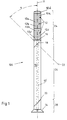
- Signal light 100 comprises a columnar or rod-shaped Base body 10 with the longitudinal axis 11 and sections 24, 26 and 28, light sources 12, a foot 14 and swivel joints 18 and 20 in Area of the base body 10. Furthermore, a swivel joint 16 be provided which has an axis of rotation which is substantially parallel is arranged to the longitudinal axis 11, while the pivot joints 18 and 20 each have an axis of rotation 22 which is at an angle ⁇ of 45 degrees to Longitudinal axis 11 is tilted.
- a swivel joint 16 be provided which has an axis of rotation which is substantially parallel is arranged to the longitudinal axis 11, while the pivot joints 18 and 20 each have an axis of rotation 22 which is at an angle ⁇ of 45 degrees to Longitudinal axis 11 is tilted.
- the housing 12a is e.g. from a red colored Material, the housing 12b made of a yellow / orange colored Material and the housing 12c from a green colored material. As other colors can be used: blue, white and yellow and also others Colors, each individually or in any combination of these Colours.
- the lamp housing 12a, 12b, 12c are dimensioned so that together with the base body 10 a columnar body, as in Fig. 1st is shown.
- the cross section of the housing 12a, 12b, 12c and the base body 10 is circular or square, but also others Geometric cross-sectional shapes can be used.
- the basic body 10 and the lamp housing 12a, 12b, 12c are as individual components formed and with the interposition of intermediate rings 10a, 10b, 10c and use of an upper cover plate 10d e.g. mediated a connecting rod arranged inside the signal lamp with each other releasably connected. All components can also be fixed together be connected.
- the base body 10 is rod-shaped
- the three are Light sources placed on the rod-shaped base body 10 in the manner of traffic lights, which is indicated at 10 in FIG. 1.
- the number of light sources 12 can be any. In the standard e.g. no more than five Elements provided.
- the sections 24 and 26 of the Base body 10 rotatable against each other. Due to the tilted axis of rotation 22 pivots section 24 from the direction of the longitudinal axis 11 out and, depending on the angle of rotation about the hinge 18 to a predetermined angle to section 26 or to longitudinal axis 11 tilted. With an angle of rotation of 180 degrees about the axis of rotation 22 results through the 45-degree inclination of the axis of rotation 22 an angle between sections 24 and 26 of 90 degrees.
- the signal lamp 100 can be placed on the floor or attachable to floor or wall.
- the signal lamp can be aligned accordingly, so that the Luminous sources 12 light for signaling purposes, for example for identification a danger point e.g. in traffic, for example radiate a predetermined direction.
- the light sources 12 can, however also be designed as rotating lights so that the swivel joint 16 superfluous.
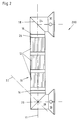
- a second preferred embodiment of a Signal light 200 is shown in Figures 2 to 5.
- the light sources 12 between the two Swivel joints 18 and 20 arranged with tilted axis of rotation 22 and on both ends of the base body 10, that is to say at the sections 24 and 28, mounting feet 30 are formed.
- the fastening feet 30 are of this type by means of the swivel joints 16, 18 and 20 bendable by 90 degrees with respect to the longitudinal axis 11 so that an upright, lateral wall mounting of the light sources 12 in a vertical arrangement is possible, as shown in Fig. 2.
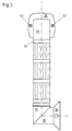
- Figures 3, 4 and 5 show others Arrangement options for the mounting feet 30.
- Fig.5 there are Mounting holes 32 of the mounting foot 30 can be seen through which, for example, for wall mounting, screws passed through and screwed into a wall.
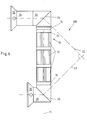
- FIG. 6 shows a third embodiment of a signal lamp 300. This differs from the previous embodiments 100 and 200 an additional hinge 34 with tilted with respect to the longitudinal axis 11 Axis of rotation 22 and an additional section 36.
- the section 36 is rotated about the pivot 34, so that between section 36 and section 26 an angle of 90 Degree is formed.
- the one or more pivot joints 16 are also used for Twisting the mounting feet 30 against each other, so that for example on different walls or wall and ceiling or Wall and floor can be attached.
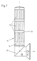
- the fourth preferred embodiment shown in Figure 7 of an inventive Signal lamp 400 comprises, in contrast to the previous ones Embodiments 100, 200 and 300 only have a swivel joint 20 with respect to the longitudinal axis 11 tilted axis of rotation 22 and only one hinge 16 with the axis of rotation not tilted.
- Section 28 is included against section 26 of base body 10 at an angle of 90 Degrees tilted about the pivot 20.
- the pivot 16 is, as with all previous embodiments 100, 200 and 300, optional and unnecessary for example with all-round light sources 12.
- All of the signal lights 100 to 400 shown in FIGS. 1 to 7 are as Multiple lamp designed and have three independently of each other controllable light sources 12 in glass bodies, these glass bodies have different colors and adapt to the columnar character of the signal light 100 to 400 one above the other are arranged.
- Electronic components for the control of the individual lights 12 are in the columnar shape or section 24, 26, 28 and / or 36 of the base body 10 of the signal lamp are arranged.
- the body or base body 10 of the signal lamp 100 to 400 designed so that individual shaft sections 24, 26, 28, 36 Above and / or below the light segments 12 are angled.
- the embodiments 100 and 400 have the light segments 12 in upper section 24, so that then the bend options in lower shaft 26 and 28 are provided.
- the embodiments 200 and 300 is the light segment 12 between two shaft sections 24 and 28 arranged so that the shaft sections 24, 26, 28, 36 above and / or are formed below the light segment 12, that individual sections 24, 26, 28, 36 can be angled, wherein these angled sections 24, 26, 28, 36 at their ends mounting brackets 30 have.
- the columnar advantageously has Body 10 of the signal lamp 100 to 400 a circular Cross section on.
- these bendable sections are separate to the remaining column section arranged, the dividing line a course of 90 degrees or 45 degrees to the longitudinal axis 11 of the columnar signal light 100 to 400.
- the axes of rotation 22 shown can, as shown by way of example, with an angle of 45 degrees Longitudinal axis 11 run, but these can also, for example, in any angle from greater than 0 degrees to less than or equal to 90 Degree to the longitudinal axis 11.
- the axes of rotation 22 different pivots 18 and 20 are not necessarily parallel to each other aligned, but can turn around a predetermined Angle be tilted to each other.
- both Axes of rotation 22 of the rotary joints 18 and 20 to an angle of 45 degrees Have longitudinal axis 11, but against each other an angle of 90 degrees have, as shown for example in Fig.6.
- the bends shown in FIGS. 2 to 7 are twisted of the bendable sections 24, 26, 28, 36 about the longitudinal axis of the column 11 reached.
- This rotatability can take place by means of guides, whereby the cohesive column parts are held together or sections 24, 26, 28, 36 by means of spring force or other suitable Means occur when in the area of a dividing line of the rotary joints 16, 18, 20, 34 no other guides are provided.
- the guides should be such that one part 24, 26, 28, 36 on the other part 24, 26, 28, 36 is held rotatably.
- angular ranges or rotating ranges of the swivel joints 16, 18, 20, 34 of the bendable sections 24, 26, 28, 36 are then in Interior of the signal light 100 to 400 led electrical lines arranged, either in this rotation range via sliding contacts and Slip rings are connected, so that in this embodiment Twist the bendable sections as often and in any number Direction can be made.
- the bendable column sections have contacts 24, 26, 28, 36 only a limited, predetermined range of rotation, which allows the angled column section into the angled Position.
Landscapes
- Engineering & Computer Science (AREA)
- General Engineering & Computer Science (AREA)
- Non-Portable Lighting Devices Or Systems Thereof (AREA)
- Liquid Crystal (AREA)
- Optical Head (AREA)
- Optical Communication System (AREA)
- Fastening Of Light Sources Or Lamp Holders (AREA)
Applications Claiming Priority (2)
| Application Number | Priority Date | Filing Date | Title |
|---|---|---|---|
| DE29716867U | 1997-09-19 | ||
| DE29716867U DE29716867U1 (de) | 1997-09-19 | 1997-09-19 | Signalleuchte |
Publications (3)
| Publication Number | Publication Date |
|---|---|
| EP0903534A2 true EP0903534A2 (fr) | 1999-03-24 |
| EP0903534A3 EP0903534A3 (fr) | 2000-11-08 |
| EP0903534B1 EP0903534B1 (fr) | 2007-01-24 |
Family
ID=8046251
Family Applications (1)
| Application Number | Title | Priority Date | Filing Date |
|---|---|---|---|
| EP98114032A Expired - Lifetime EP0903534B1 (fr) | 1997-09-19 | 1998-07-28 | Lampe de signalisation |
Country Status (3)
| Country | Link |
|---|---|
| EP (1) | EP0903534B1 (fr) |
| AT (1) | ATE352748T1 (fr) |
| DE (2) | DE29716867U1 (fr) |
Cited By (3)
| Publication number | Priority date | Publication date | Assignee | Title |
|---|---|---|---|---|
| WO2004099665A1 (fr) * | 2003-05-10 | 2004-11-18 | A+G Schreder Gmbh | Dispositif d'eclairage |
| EP2320126A1 (fr) * | 2009-11-10 | 2011-05-11 | Mizza Renato Di Balzarotti Ambrogio | Dispositif de signalisation lumineuse |
| DE102018002190A1 (de) | 2018-03-17 | 2019-09-19 | Hess GmbH Licht + Form | Leuchtenmast |
Families Citing this family (2)
| Publication number | Priority date | Publication date | Assignee | Title |
|---|---|---|---|---|
| CH703004A1 (de) * | 2010-04-30 | 2011-10-31 | Tipper Tie Alpina Gmbh | Warnleuchte an einer Lebensmittel verarbeitenden Maschine. |
| DE202012003647U1 (de) | 2012-04-11 | 2012-10-19 | Sonlux Licht- Und Elektroinstallation Gmbh & Co. Kg Sondershausen | Mobile Großflächenbeleuchtungseinrichtung |
Family Cites Families (4)
| Publication number | Priority date | Publication date | Assignee | Title |
|---|---|---|---|---|
| DE2036853C3 (de) * | 1970-07-24 | 1974-05-09 | Siemens Ag, 1000 Berlin Und 8000 Muenchen | Lichtsignalgeber, insbesondere für den Straßenverkehr |
| FR2128998A5 (fr) * | 1971-03-10 | 1972-10-27 | Telemecanique Electrique | |
| DE3611013C2 (de) * | 1986-04-02 | 1996-07-18 | Hartmut S Engel | Leuchte |
| US4716505A (en) * | 1987-02-13 | 1987-12-29 | New Horizons Product Development Company Limited | Table lamps |
-
1997
- 1997-09-19 DE DE29716867U patent/DE29716867U1/de not_active Expired - Lifetime
-
1998
- 1998-07-28 DE DE59813886T patent/DE59813886D1/de not_active Expired - Fee Related
- 1998-07-28 EP EP98114032A patent/EP0903534B1/fr not_active Expired - Lifetime
- 1998-07-28 AT AT98114032T patent/ATE352748T1/de not_active IP Right Cessation
Non-Patent Citations (1)
| Title |
|---|
| None |
Cited By (4)
| Publication number | Priority date | Publication date | Assignee | Title |
|---|---|---|---|---|
| WO2004099665A1 (fr) * | 2003-05-10 | 2004-11-18 | A+G Schreder Gmbh | Dispositif d'eclairage |
| EP2320126A1 (fr) * | 2009-11-10 | 2011-05-11 | Mizza Renato Di Balzarotti Ambrogio | Dispositif de signalisation lumineuse |
| DE102018002190A1 (de) | 2018-03-17 | 2019-09-19 | Hess GmbH Licht + Form | Leuchtenmast |
| DE102018002190B4 (de) * | 2018-03-17 | 2020-02-06 | Hess GmbH Licht + Form | Leuchtenmast |
Also Published As
| Publication number | Publication date |
|---|---|
| EP0903534B1 (fr) | 2007-01-24 |
| ATE352748T1 (de) | 2007-02-15 |
| DE29716867U1 (de) | 1997-11-13 |
| EP0903534A3 (fr) | 2000-11-08 |
| DE59813886D1 (de) | 2007-03-15 |
Similar Documents
| Publication | Publication Date | Title |
|---|---|---|
| DE20305579U1 (de) | Garagentorantrieb mit Leuchteinheit | |
| DE102012206988A1 (de) | Leuchte | |
| AT402627B (de) | Nummerntafel mit leuchtkennzeichen nummerntafel mit leuchtkennzeichen | |
| EP0913625A2 (fr) | Lampe de signalisation | |
| DE3811740A1 (de) | Niederspannungsbeleuchtungssystem | |
| EP0903534A2 (fr) | Lampe de signalisation | |
| DE202012004210U1 (de) | Leuchte | |
| DE3246985C2 (fr) | ||
| EP0608486A1 (fr) | Dispositif de présentation d'information | |
| DE102007011986A1 (de) | Anzeigevorrichtung mit Halteelement | |
| DE102011110580A1 (de) | Leuchte, insbesondere Straßenleuchte mit LEDs | |
| EP2484961B1 (fr) | Recouvrement pour un boîtier de lampes | |
| DE2217249A1 (de) | Vorrichtung an einer fluoreszenzroehre zum regulieren der richtung und/oder der groesse des lichtstromes | |
| DE102010013649A1 (de) | Leuchte | |
| DE29622190U1 (de) | Beleuchtungsvorrichtung | |
| EP3073178A1 (fr) | Éclairage et systeme d'eclairage | |
| DE202020101584U1 (de) | Multifunktionale Beleuchtungseinrichtung für die Schönheitspflege von Kraftfahrzeugen | |
| DE19725776C1 (de) | Lichtstreuende Abdeckscheibe als Bestandteil einer Niedervoltleuchte | |
| EP4258307A1 (fr) | Appareil de technique d'installation domestique | |
| DE3202927A1 (de) | Lampe zur erzeugung farbiger lichtwirkungen | |
| DE3013137A1 (de) | Vorrichtung zur aenderung der einstellung der scheinwerfer an kraftfahrzeugen in abhaengigkeit von der befoerderten last | |
| DE2548218A1 (de) | Beleuchtungseinrichtung | |
| DE10300650B3 (de) | Verbindungselement für einen Handlauf | |
| DE20000695U1 (de) | Pendelleuchte | |
| DE1985656U (de) | Hand- und warnleuchte. |
Legal Events
| Date | Code | Title | Description |
|---|---|---|---|
| PUAI | Public reference made under article 153(3) epc to a published international application that has entered the european phase |
Free format text: ORIGINAL CODE: 0009012 |
|
| AK | Designated contracting states |
Kind code of ref document: A2 Designated state(s): AT CH DE FR IT LI |
|
| AX | Request for extension of the european patent |
Free format text: AL;LT;LV;MK;RO;SI |
|
| PUAL | Search report despatched |
Free format text: ORIGINAL CODE: 0009013 |
|
| AK | Designated contracting states |
Kind code of ref document: A3 Designated state(s): AT BE CH CY DE DK ES FI FR GB GR IE IT LI LU MC NL PT SE |
|
| AX | Request for extension of the european patent |
Free format text: AL;LT;LV;MK;RO;SI |
|
| 17P | Request for examination filed |
Effective date: 20001223 |
|
| AKX | Designation fees paid |
Free format text: AT CH DE FR IT LI |
|
| RAP1 | Party data changed (applicant data changed or rights of an application transferred) |
Owner name: PFANNENBERG GMBH |
|
| GRAP | Despatch of communication of intention to grant a patent |
Free format text: ORIGINAL CODE: EPIDOSNIGR1 |
|
| GRAS | Grant fee paid |
Free format text: ORIGINAL CODE: EPIDOSNIGR3 |
|
| RIC1 | Information provided on ipc code assigned before grant |
Ipc: F21V 21/30 20060101ALI20061109BHEP Ipc: F21S 8/00 20060101AFI20061109BHEP |
|
| GRAA | (expected) grant |
Free format text: ORIGINAL CODE: 0009210 |
|
| AK | Designated contracting states |
Kind code of ref document: B1 Designated state(s): AT CH DE FR IT LI |
|
| REG | Reference to a national code |
Ref country code: CH Ref legal event code: EP |
|
| REF | Corresponds to: |
Ref document number: 59813886 Country of ref document: DE Date of ref document: 20070315 Kind code of ref document: P |
|
| ET | Fr: translation filed | ||
| PLBE | No opposition filed within time limit |
Free format text: ORIGINAL CODE: 0009261 |
|
| STAA | Information on the status of an ep patent application or granted ep patent |
Free format text: STATUS: NO OPPOSITION FILED WITHIN TIME LIMIT |
|
| 26N | No opposition filed |
Effective date: 20071025 |
|
| PGFP | Annual fee paid to national office [announced via postgrant information from national office to epo] |
Ref country code: FR Payment date: 20090720 Year of fee payment: 12 |
|
| PGFP | Annual fee paid to national office [announced via postgrant information from national office to epo] |
Ref country code: CH Payment date: 20090727 Year of fee payment: 12 Ref country code: AT Payment date: 20090723 Year of fee payment: 12 |
|
| PGFP | Annual fee paid to national office [announced via postgrant information from national office to epo] |
Ref country code: DE Payment date: 20090923 Year of fee payment: 12 |
|
| PGFP | Annual fee paid to national office [announced via postgrant information from national office to epo] |
Ref country code: IT Payment date: 20090727 Year of fee payment: 12 |
|
| REG | Reference to a national code |
Ref country code: CH Ref legal event code: PL |
|
| REG | Reference to a national code |
Ref country code: FR Ref legal event code: ST Effective date: 20110331 |
|
| PG25 | Lapsed in a contracting state [announced via postgrant information from national office to epo] |
Ref country code: DE Free format text: LAPSE BECAUSE OF NON-PAYMENT OF DUE FEES Effective date: 20110201 Ref country code: LI Free format text: LAPSE BECAUSE OF NON-PAYMENT OF DUE FEES Effective date: 20100731 Ref country code: CH Free format text: LAPSE BECAUSE OF NON-PAYMENT OF DUE FEES Effective date: 20100731 |
|
| REG | Reference to a national code |
Ref country code: DE Ref legal event code: R119 Ref document number: 59813886 Country of ref document: DE Effective date: 20110201 |
|
| PG25 | Lapsed in a contracting state [announced via postgrant information from national office to epo] |
Ref country code: IT Free format text: LAPSE BECAUSE OF NON-PAYMENT OF DUE FEES Effective date: 20100728 Ref country code: FR Free format text: LAPSE BECAUSE OF NON-PAYMENT OF DUE FEES Effective date: 20100802 Ref country code: AT Free format text: LAPSE BECAUSE OF NON-PAYMENT OF DUE FEES Effective date: 20100728 |