EP0903534A2 - Signal lamp - Google Patents
Signal lamp Download PDFInfo
- Publication number
- EP0903534A2 EP0903534A2 EP98114032A EP98114032A EP0903534A2 EP 0903534 A2 EP0903534 A2 EP 0903534A2 EP 98114032 A EP98114032 A EP 98114032A EP 98114032 A EP98114032 A EP 98114032A EP 0903534 A2 EP0903534 A2 EP 0903534A2
- Authority
- EP
- European Patent Office
- Prior art keywords
- signal light
- base body
- rotation
- swivel joint
- light
- Prior art date
- Legal status (The legal status is an assumption and is not a legal conclusion. Google has not performed a legal analysis and makes no representation as to the accuracy of the status listed.)
- Granted
Links
Images


Classifications
-
- F—MECHANICAL ENGINEERING; LIGHTING; HEATING; WEAPONS; BLASTING
- F21—LIGHTING
- F21V—FUNCTIONAL FEATURES OR DETAILS OF LIGHTING DEVICES OR SYSTEMS THEREOF; STRUCTURAL COMBINATIONS OF LIGHTING DEVICES WITH OTHER ARTICLES, NOT OTHERWISE PROVIDED FOR
- F21V21/00—Supporting, suspending, or attaching arrangements for lighting devices; Hand grips
- F21V21/14—Adjustable mountings
- F21V21/30—Pivoted housings or frames
-
- F—MECHANICAL ENGINEERING; LIGHTING; HEATING; WEAPONS; BLASTING
- F21—LIGHTING
- F21S—NON-PORTABLE LIGHTING DEVICES; SYSTEMS THEREOF; VEHICLE LIGHTING DEVICES SPECIALLY ADAPTED FOR VEHICLE EXTERIORS
- F21S8/00—Lighting devices intended for fixed installation
-
- F—MECHANICAL ENGINEERING; LIGHTING; HEATING; WEAPONS; BLASTING
- F21—LIGHTING
- F21W—INDEXING SCHEME ASSOCIATED WITH SUBCLASSES F21K, F21L, F21S and F21V, RELATING TO USES OR APPLICATIONS OF LIGHTING DEVICES OR SYSTEMS
- F21W2111/00—Use or application of lighting devices or systems for signalling, marking or indicating, not provided for in codes F21W2102/00 – F21W2107/00
- F21W2111/02—Use or application of lighting devices or systems for signalling, marking or indicating, not provided for in codes F21W2102/00 – F21W2107/00 for roads, paths or the like
Definitions
- the invention relates to a signal lamp with a longitudinal axis Base body and at least one arranged on the base body Luminous source, according to the preamble of claim 1.
- Generic signal lights have the disadvantage that they are only very are inflexible, i.e. the respective physical form determines whether the signal light exclusively as a floor, wall, or Mobile signal light can be used.
- the base body at least has a swivel with an axis of rotation about which at least two sections of the base body against each other, i.e. preferably are each rotatable through 180 ° through a 45 ° slope.
- the predetermined angle between the axis of rotation of the pivot joint and the longitudinal axis is 0 ⁇ ⁇ 90 degrees, in particular 45 degrees, can two sections of the body to each other by 90 degrees be angled.
- the axis of rotation and are expedient the longitudinal axis of at least one swivel is arranged such that they either have a common intersection or have no common one Intersection point anywhere in the room.
- a mechanically particularly simple and inexpensive embodiment has at least one hinge stops, which a rotation about this hinge to a predetermined angle of rotation limit.
- the base body is rod-shaped or columnar, the base body a round, triangular, quadrangular or polygonal cross section having.
- multiple light are particularly preferred Way at least two, in particular three light sources Base body arranged, wherein a controller is advantageously provided which controls the light sources independently of each other.
- a particularly good light emission characteristic and corresponding Signal function is achieved in that the at least one light source is arranged in a vitreous body, the vitreous body being preferred colored, especially in red, yellow or green. Furthermore, it is this is advantageous if the at least one light source is designed in this way is that they are parallel or perpendicular to a longitudinal axis of the base body, especially at a 360 degree angle, light emits.
- a base is arranged on at least one end of the base body.
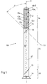
- Signal light 100 comprises a columnar or rod-shaped Base body 10 with the longitudinal axis 11 and sections 24, 26 and 28, light sources 12, a foot 14 and swivel joints 18 and 20 in Area of the base body 10. Furthermore, a swivel joint 16 be provided which has an axis of rotation which is substantially parallel is arranged to the longitudinal axis 11, while the pivot joints 18 and 20 each have an axis of rotation 22 which is at an angle ⁇ of 45 degrees to Longitudinal axis 11 is tilted.
- a swivel joint 16 be provided which has an axis of rotation which is substantially parallel is arranged to the longitudinal axis 11, while the pivot joints 18 and 20 each have an axis of rotation 22 which is at an angle ⁇ of 45 degrees to Longitudinal axis 11 is tilted.
- the housing 12a is e.g. from a red colored Material, the housing 12b made of a yellow / orange colored Material and the housing 12c from a green colored material. As other colors can be used: blue, white and yellow and also others Colors, each individually or in any combination of these Colours.
- the lamp housing 12a, 12b, 12c are dimensioned so that together with the base body 10 a columnar body, as in Fig. 1st is shown.
- the cross section of the housing 12a, 12b, 12c and the base body 10 is circular or square, but also others Geometric cross-sectional shapes can be used.
- the basic body 10 and the lamp housing 12a, 12b, 12c are as individual components formed and with the interposition of intermediate rings 10a, 10b, 10c and use of an upper cover plate 10d e.g. mediated a connecting rod arranged inside the signal lamp with each other releasably connected. All components can also be fixed together be connected.
- the base body 10 is rod-shaped
- the three are Light sources placed on the rod-shaped base body 10 in the manner of traffic lights, which is indicated at 10 in FIG. 1.
- the number of light sources 12 can be any. In the standard e.g. no more than five Elements provided.
- the sections 24 and 26 of the Base body 10 rotatable against each other. Due to the tilted axis of rotation 22 pivots section 24 from the direction of the longitudinal axis 11 out and, depending on the angle of rotation about the hinge 18 to a predetermined angle to section 26 or to longitudinal axis 11 tilted. With an angle of rotation of 180 degrees about the axis of rotation 22 results through the 45-degree inclination of the axis of rotation 22 an angle between sections 24 and 26 of 90 degrees.
- the signal lamp 100 can be placed on the floor or attachable to floor or wall.
- the signal lamp can be aligned accordingly, so that the Luminous sources 12 light for signaling purposes, for example for identification a danger point e.g. in traffic, for example radiate a predetermined direction.
- the light sources 12 can, however also be designed as rotating lights so that the swivel joint 16 superfluous.
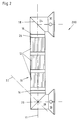
- a second preferred embodiment of a Signal light 200 is shown in Figures 2 to 5.
- the light sources 12 between the two Swivel joints 18 and 20 arranged with tilted axis of rotation 22 and on both ends of the base body 10, that is to say at the sections 24 and 28, mounting feet 30 are formed.
- the fastening feet 30 are of this type by means of the swivel joints 16, 18 and 20 bendable by 90 degrees with respect to the longitudinal axis 11 so that an upright, lateral wall mounting of the light sources 12 in a vertical arrangement is possible, as shown in Fig. 2.
- Figures 3, 4 and 5 show others Arrangement options for the mounting feet 30.
- Fig.5 there are Mounting holes 32 of the mounting foot 30 can be seen through which, for example, for wall mounting, screws passed through and screwed into a wall.
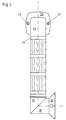
- FIG. 6 shows a third embodiment of a signal lamp 300. This differs from the previous embodiments 100 and 200 an additional hinge 34 with tilted with respect to the longitudinal axis 11 Axis of rotation 22 and an additional section 36.
- the section 36 is rotated about the pivot 34, so that between section 36 and section 26 an angle of 90 Degree is formed.
- the one or more pivot joints 16 are also used for Twisting the mounting feet 30 against each other, so that for example on different walls or wall and ceiling or Wall and floor can be attached.
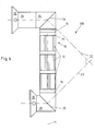
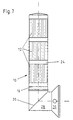
- the fourth preferred embodiment shown in Figure 7 of an inventive Signal lamp 400 comprises, in contrast to the previous ones Embodiments 100, 200 and 300 only have a swivel joint 20 with respect to the longitudinal axis 11 tilted axis of rotation 22 and only one hinge 16 with the axis of rotation not tilted.
- Section 28 is included against section 26 of base body 10 at an angle of 90 Degrees tilted about the pivot 20.
- the pivot 16 is, as with all previous embodiments 100, 200 and 300, optional and unnecessary for example with all-round light sources 12.
- All of the signal lights 100 to 400 shown in FIGS. 1 to 7 are as Multiple lamp designed and have three independently of each other controllable light sources 12 in glass bodies, these glass bodies have different colors and adapt to the columnar character of the signal light 100 to 400 one above the other are arranged.
- Electronic components for the control of the individual lights 12 are in the columnar shape or section 24, 26, 28 and / or 36 of the base body 10 of the signal lamp are arranged.
- the body or base body 10 of the signal lamp 100 to 400 designed so that individual shaft sections 24, 26, 28, 36 Above and / or below the light segments 12 are angled.
- the embodiments 100 and 400 have the light segments 12 in upper section 24, so that then the bend options in lower shaft 26 and 28 are provided.
- the embodiments 200 and 300 is the light segment 12 between two shaft sections 24 and 28 arranged so that the shaft sections 24, 26, 28, 36 above and / or are formed below the light segment 12, that individual sections 24, 26, 28, 36 can be angled, wherein these angled sections 24, 26, 28, 36 at their ends mounting brackets 30 have.
- the columnar advantageously has Body 10 of the signal lamp 100 to 400 a circular Cross section on.
- these bendable sections are separate to the remaining column section arranged, the dividing line a course of 90 degrees or 45 degrees to the longitudinal axis 11 of the columnar signal light 100 to 400.
- the axes of rotation 22 shown can, as shown by way of example, with an angle of 45 degrees Longitudinal axis 11 run, but these can also, for example, in any angle from greater than 0 degrees to less than or equal to 90 Degree to the longitudinal axis 11.
- the axes of rotation 22 different pivots 18 and 20 are not necessarily parallel to each other aligned, but can turn around a predetermined Angle be tilted to each other.
- both Axes of rotation 22 of the rotary joints 18 and 20 to an angle of 45 degrees Have longitudinal axis 11, but against each other an angle of 90 degrees have, as shown for example in Fig.6.
- the bends shown in FIGS. 2 to 7 are twisted of the bendable sections 24, 26, 28, 36 about the longitudinal axis of the column 11 reached.
- This rotatability can take place by means of guides, whereby the cohesive column parts are held together or sections 24, 26, 28, 36 by means of spring force or other suitable Means occur when in the area of a dividing line of the rotary joints 16, 18, 20, 34 no other guides are provided.
- the guides should be such that one part 24, 26, 28, 36 on the other part 24, 26, 28, 36 is held rotatably.
- angular ranges or rotating ranges of the swivel joints 16, 18, 20, 34 of the bendable sections 24, 26, 28, 36 are then in Interior of the signal light 100 to 400 led electrical lines arranged, either in this rotation range via sliding contacts and Slip rings are connected, so that in this embodiment Twist the bendable sections as often and in any number Direction can be made.
- the bendable column sections have contacts 24, 26, 28, 36 only a limited, predetermined range of rotation, which allows the angled column section into the angled Position.
Landscapes
- Engineering & Computer Science (AREA)
- General Engineering & Computer Science (AREA)
- Non-Portable Lighting Devices Or Systems Thereof (AREA)
- Optical Communication System (AREA)
- Liquid Crystal (AREA)
- Optical Head (AREA)
- Fastening Of Light Sources Or Lamp Holders (AREA)
Abstract
Um eine Signalleuchte (100) mit einem eine Längsachse (11) aufweisenden
Grundkörper (10) und mit wenigstens einer an dem Grundkörper
angeordneten Leuchtquelle (12) unterschiedlicher Einsatzbedingungen
und -zwecken anpassen zu können, weist der säulen- oder
stabförmige Grundkörper (10) wenigstens ein Drehgelenk (16,18,20)
mit einer Drehachse (22) auf, um den wenigstens zwei Abschnitte (24,26,
28) des Grundkörpers (10) gegeneinander drehbar sind.

Description
Die Erfindung betrifft eine Signalleuchte mit einem eine Längsachse aufweisenden Grundkörper und wenigstens einer an dem Grundkörper angeordneten Leuchtquelle, gemäß dem Oberbegriff des Anspruchs 1.The invention relates to a signal lamp with a longitudinal axis Base body and at least one arranged on the base body Luminous source, according to the preamble of claim 1.
Gattungsgemäße Signalleuchten haben den Nachteil, daß sie nur sehr unflexibel einsetzbar sind, d.h. die jeweilige körperliche Ausgestaltung bestimmt, ob die Signalleuchte ausschließlich als Boden-, Wand-, oder Mobilsignalleuchte einsetzbar ist.Generic signal lights have the disadvantage that they are only very are inflexible, i.e. the respective physical form determines whether the signal light exclusively as a floor, wall, or Mobile signal light can be used.
Es ist Aufgabe der vorliegenden Erfindung, eine verbesserte Signalleuchte der obengenannten Art zur Verfügung zu stellen, welche die obengenannten Nachteile beseitigt.It is an object of the present invention to provide an improved signal lamp of the type mentioned above, which the above Disadvantages eliminated.
Diese Aufgabe wird durch eine Signalleuchte der o.g. Art mit den in Anspruch 1 gekennzeichneten Merkmalen gelöst.This task is carried out by a signal lamp of the above. Kind with the claim 1 marked features solved.
Dazu ist es erfindungsgemäß vorgesehen, daß der Grundkörper wenigstens ein Drehgelenk mit einer Drehachse aufweist, um den wenigstens zwei Abschnitte des Grundkörpers gegeneinander, d.h. bevorzugterweise jeweils um 180° über eine 45°-Schräge drehbar sind.For this purpose, it is provided according to the invention that the base body at least has a swivel with an axis of rotation about which at least two sections of the base body against each other, i.e. preferably are each rotatable through 180 ° through a 45 ° slope.
Dies hat den Vorteil, daß die erfindungsgemäße Signalleuchte auf unterschiedlichste Weisen und angepaßt an unterschiedlichste Einsatzbedingungen und Einsatzzwecke einsetzbar ist.This has the advantage that the signal light according to the invention on different Wise and adapted to different operating conditions and uses can be used.
Vorzugsweise Weitergestaltungen der Vorrichtung sind in den Ansprüchen 2 bis 20 beschrieben. Further developments of the device are preferred in the claims 2 to 20 described.
So ergibt sich eine besonders flexibel einsetzbare Anordnung dadurch, daß die Drehachse wenigstens eines Drehgelenkes um einen vorbestimmten Winkel bezüglich der Längsachse des Grundkörpers verkippt ist.This results in a particularly flexible arrangement because that the axis of rotation of at least one hinge about a predetermined Angle with respect to the longitudinal axis of the base body is tilted.
Dadurch, daß der vorbestimmte Winkel zwischen Drehachse des Drehgelenkes und Längsachse 0 < α < 90 Grad, insbesondere 45 Grad, beträgt, können zwei Abschnitte des Grundkörpers um 90 Grad zueinander abgewinkelt werden. Zweckmäßigerweise sind dabei die Drehachse und die Längsachse wenigstens eines Drehgelenkes derart angeordnet, daß sie entweder einen gemeinsamen Schnittpunkt haben oder ohne gemeinsamen Schnittpunkt beliebig im Raum liegen.The fact that the predetermined angle between the axis of rotation of the pivot joint and the longitudinal axis is 0 <α <90 degrees, in particular 45 degrees, can two sections of the body to each other by 90 degrees be angled. The axis of rotation and are expedient the longitudinal axis of at least one swivel is arranged such that they either have a common intersection or have no common one Intersection point anywhere in the room.
In einer mechanisch besonders einfachen und kostengünstigen Ausführungsform weist wenigstens ein Drehgelenk Anschläge auf, welche eine Drehung um dieses Drehgelenk auf einen vorbestimmten Drehwinkel begrenzen. Dabei sind an dem Drehgelenk Kontakteinrichtungen zwischen der wenigstens einen Leuchteinrichtung und einer Spannungsversorgung vorgesehen, welche eine dem begrenzten Drehwinkel folgende Drahtschleife umfaßt.In a mechanically particularly simple and inexpensive embodiment has at least one hinge stops, which a rotation about this hinge to a predetermined angle of rotation limit. There are contact devices on the swivel joint between the at least one lighting device and a voltage supply provided which the the limited angle of rotation includes the following wire loop.
In einer besonders bevorzugten Ausführungsform ist wenigstens ein Drehgelenk als endlos drehbares Drehgelenk ausgebildet. Dabei ist in vorteilharter Weise an dem Drehgelenk eine Kontakteinrichtung zwischen der wenigstens einen Leuchteinrichtung und einer Spannungsversorgung vorgesehen, welcher einen endlos drehbaren Schleifkontakt umfaßt.In a particularly preferred embodiment, there is at least one swivel joint designed as an endlessly rotatable swivel. It is more advantageous Way on the pivot joint a contact device between the at least one lighting device and a voltage supply are provided, which comprises an endlessly rotatable sliding contact.
Eine besonders gute Handhabbarkeit wird dadurch erzielt, daß der Grundkörper stabförmig oder säulenförmig ausgebildet ist, wobei der Grundkörper einen runden, dreieckigen, viereckigen oder vieleckigen Querschnitt aufweist.A particularly good handling is achieved in that the base body is rod-shaped or columnar, the base body a round, triangular, quadrangular or polygonal cross section having.
Zur weiteren Verbesserung der Anpaßbarkeit an unterschiedlichste Einsatzbedingungen sind wenigstens zwei, insbesondere drei Drehgelenke vorgesehen, wobei insbesondere die wenigstens eine Leuchtquelle zwischen zwei Drehgelenken angeordnet ist.To further improve adaptability to a wide variety of operating conditions are at least two, especially three swivel joints provided, in particular the at least one light source is arranged between two swivel joints.
In einer Ausführungsform als Mehrfachleuchte sind in besonders bevorzugter Weise wenigstens zwei, insbesondere drei Leuchtquellen am Grundkörper angeordnet, wobei in vorteilhafter Weise eine Steuerung vorgesehen ist, welche die Leuchtquellen unabhängig voneinander ansteuert.In one embodiment as a multiple light are particularly preferred Way at least two, in particular three light sources Base body arranged, wherein a controller is advantageously provided which controls the light sources independently of each other.
Eine besonders gute Lichtabstrahlcharakteristik und entsprechende Signalfunktion erzielt man dadurch, daß die wenigstens eine Leuchtquelle in einem Glaskörper angeordnet ist, wobei der Glaskörper bevorzugt farbig, insbesondere in rot, gelb oder grün, ausgebildet ist. Ferner ist es hierbei von Vorteil, wenn die wenigstens eine Leuchtquelle derart ausgebildet ist, daß sie parallel oder senkrecht zu einer Längsachse des Grundkörpers, insbesondere in einem 360 Grad Winkel, Licht abstrahlt.A particularly good light emission characteristic and corresponding Signal function is achieved in that the at least one light source is arranged in a vitreous body, the vitreous body being preferred colored, especially in red, yellow or green. Furthermore, it is this is advantageous if the at least one light source is designed in this way is that they are parallel or perpendicular to a longitudinal axis of the base body, especially at a 360 degree angle, light emits.
Für ein einfaches mobiles Aufstellen der Signalleuchte am Einsatzort ist an wenigstens einem Ende des Grundkörpers ein Standfuß angeordnet.For easy mobile installation of the signal lamp at the place of use a base is arranged on at least one end of the base body.
Für eine dauerhafte, feste Montage ist an wenigstens einem Ende des Grundkörpers ein Fuß mit Befestigungsmitteln angeordnet, wobei die Befestigungsmittel beispielsweise Durchgangsbohrungen sind. For a permanent, firm installation, at least one end of the Base body arranged a foot with fasteners, the fasteners for example, are through holes.
Nachstehend wird die Erfindung anhand der beigefügten Zeichnungen näher erläutert. Diese zeigen in
- Fig. 1
- eine erste Ausführungsform einer Signalleuchte in einer Seitenansicht,
- Fig. 2 bis 5
- eine zweite Ausführungsform einer Signalleuchte in verschiedenen Stellungen und Seitenansichten,
- Fig. 6
- eine dritte Ausführungsform einer Signalleuchte in Seitenansicht und
- Fig. 7
- eine vierte Ausführungsform einer Signalleuchte in Seitenansicht.
- Fig. 1
- a first embodiment of a signal lamp in a side view,
- 2 to 5
- a second embodiment of a signal light in different positions and side views,
- Fig. 6
- a third embodiment of a signal lamp in side view and
- Fig. 7
- a fourth embodiment of a signal lamp in side view.
Die in Fig.1 dargestellte erste bevorzugte Ausführungsform einer
erfindungsgemäßen Signalleuchte 100 umfaßt einen säulen- oder stabförmigen
Grundkörper 10 mit der Längsachse 11 und Abschnitten 24, 26
und 28, Leuchtquellen 12, einen Fuß 14 und Drehgelenke 18 und 20 im
Bereich des Grundkörpers 10. Des weiteren kann noch ein Drehgelenk 16
vorgesehen sein, das eine Drehachse hat, welche im wesentlichen parallel
zur Längsachse 11 angeordnet ist, während die Drehgelenke 18 und 20 je
eine Drehachse 22 aufweisen, die um einen Winkel α von 45 Grad zur
Längsachse 11 verkippt ist. Bei dem Ausführungsbeispiel gemäß Fig. 1
sind drei übereinander liegend angeordnete Leuchtquellen 12 vorgesehen,
deren einzelne Gehäuse 12a, 12b, 12c aus einem glasklaren oder
transparenten, unterschiedlich eingefärbten Material, insbesondere Kunststoff,
bestehen. Das Gehäuse 12a besteht z.B. aus einem rot eingefärbtem
Material, das Gehäuse 12b aus einem gelb/orange eingefärbtem
Material und das Gehäuse 12c aus einem grün eingefärbtem Material. Als
weitere Farben sind einsetzbar: blau, weiß und gelb und auch andere
Farben, jeweils für sich allein oder in beliebigen Kombinationen dieser
Farben. In den Gehäusen 12a, 12b, 12c sind mit nicht dargestellten
Stromzuführungsleitungen verbundene Glühlampen angeordnet, bei
denen es sich auch um Glühlampen mit farbigen Glaskörpern handeln
kann, so daß dann das Gehäusematerial aus uneingefärbtem glasklaren
oder transparenten Material besteht.The first preferred embodiment shown in Fig.1
Die Leuchtengehäuse 12a, 12b, 12c sind so dimensioniert, daß zusammen
mit dem Grundkörper 10 ein säulenförmiger Körper, wie in Fig. 1
dargestellt erhalten wird. Der Querschnitt der Gehäuse 12a, 12b, 12c und
des Grundkörpers 10 ist kreisförmig oder quadratisch, jedoch auch andere
geometrische Querschnittsformen können Verwendung finden. Der Grundkörper
10 und die Leuchtengehäuse 12a, 12b, 12c sind als einzelne Bauteile
ausgebildet und unter Zwischenschaltung von Zwischenringen 10a,
10b, 10c und Verwendung einer oberen Abdeckplatte 10d z.B. vermittels
eines im Inneren der Signalleuchte angeordneten Verbindungsstabes miteinander
lösbar verbunden. Alle Bauteile können auch fest miteinander
verbunden sein.The lamp housing 12a, 12b, 12c are dimensioned so that together
with the base body 10 a columnar body, as in Fig. 1st
is shown. The cross section of the housing 12a, 12b, 12c and
the
Ist dagegen der Grundkörper 10 stabförmig ausgebildet, dann sind die drei
Leuchtquellen ampelartig auf dem stabförmigen Grundkörper 10 aufgesetzt,
der mit Fig. 1 bei 10 angedeutet ist. Die Anzahl der Leuchtquellen
12 kann beliebig sein. Im Standard werden z.B. nicht mehr als fünf
Elemente vorgesehen. If, on the other hand, the
Beispielsweise um das Drehgelenk 18 sind die Abschnitte 24 und 26 des
Grundkörpers 10 gegeneinander verdrehbar. Durch die verkippte Drehachse
22 schwenkt dabei der Abschnitt 24 aus der Richtung der Längsachse
11 heraus und ist, je nach Drehwinkel um das Drehgelenk 18, um
einen vorbestimmten Winkel zum Abschnitt 26 bzw. zur Längsachse 11
verkippt. Bei einem Drehwinkel von 180 Grad um die Drehachse 22 ergibt
sich durch die 45-Grad-Neigung der Drehachse 22 ein Winkel zwischen
den Abschnitten 24 und 26 von 90 Grad.For example, about the
Analog das gleiche trifft für das Drehgelenk 20 und die dazu benachbarten
Abschnitte 26 und 28 zu.Analogously, the same applies to the
Mit dem Fuß 14 ist die Signalleuchte 100 auf den Boden abstellbar oder
an Boden bzw. Wand befestigbar. Durch Drehen um die Drehgelenke 16,
18 und 20 ist die Signalleuchte entsprechend ausrichtbar, so daß die
Leuchtquellen 12 Licht zu Signalzwecken, beispielsweise zur Kennzeichnung
einer Gefahrenstelle z.B. im Straßenverkehr, in beispielsweise
eine vorbestimmte Richtung ausstrahlen. Die Leuchtquellen 12 können jedoch
auch als Rundumleuchten ausgebildet sein, so daß sich das Drehgelenk
16 erübrigt.With the
Die vorstehenden Erläuterungen treffen auch für nachfolgend beschriebene
weitere Ausführungsformen zu, wobei gleiche Bezugsziffern
gleiche Teile bezeichnen. Eine zweite bevorzugte Ausführungsform einer
Signalleuchte 200 ist in den Fig.2 bis 5 dargestellt. Im Gegensatz zur Ausführungsform
100 von Fig.1 sind die Leuchtquellen 12 zwischen den zwei
Drehgelenken 18 und 20 mit verkippter Drehachse 22 angeordnet und an
beiden Enden des Grundkörpers 10, also an den Abschnitten 24 und 28,
sind Befestigungsfüße 30 ausgebildet. Ferner sind optional zwischen den
Drehgelenken 18 und 20 mit verkippter Drehachse 22 und den Leuchtquellen
12 Drehgelenke 16 mit bezüglich der Längsachse 11 nicht verkippter
Drehachse vorgesehen.The above explanations also apply to those described below
further embodiments, with the same reference numerals
designate the same parts. A second preferred embodiment of a
Mittels der Drehgelenke 16, 18 und 20 sind die Befestigungsfüße 30 derart
um 90 Grad bezüglich der Längsachse 11 abwinkelbar, daß eine aufrechte,
seitliche Wandmontage der Leuchtquellen 12 in vertikaler Anordnung
möglich ist, wie in Fig. 2 dargestellt. Fig.3, 4 und 5 zeigen weitere
Anordnungsmöglichkeiten für die Befestigungsfüße 30. In Fig.5 sind dabei
Befestigungslöcher 32 des Befestigungsfusses 30 erkennbar, durch
welche, beispielsweise für eine Wandbefestigung, Schrauben hindurch geführt
und in eine Wand eingeschraubt werden.The
Fig.6 zeigt eine dritte Ausführungsform einer Signalleuchte 300. Diese
weist im Unterschied zu den vorherigen Ausführungsformen 100 und 200
ein zusätzliches Drehgelenk 34 mit bezüglich der Längsachse 11 verkippter
Drehachse 22 und einen zusätzlichen Abschnitt 36 auf. In der Darstellung
von Fig.6 ist der Abschnitt 36 um das Drehgelenk 34 gedreht, so
daß zwischen dem Abschnitt 36 und dem Abschnitt 26 ein Winkel von 90
Grad gebildet ist. Das oder die Drehgelenke 16 dienen dabei auch zum
Verdrehen der Befestigungsfüße 30 gegeneinander, so daß diese beispielsweise
an unterschiedlichen Wänden bzw. Wand und Decke bzw.
Wand und Boden befestigbar sind.6 shows a third embodiment of a
Die in Fig.7 dargestellte vierte bevorzugte Ausführungsform einer erfindungsgemäßen
Signalleuchte 400 umfaßt um Gegensatz zu den vorherigen
Ausführungsformen 100, 200 und 300 nur ein Drehgelenk 20 mit
bezüglich der Längsachse 11 verkippter Drehachse 22 und nur ein Drehgelenk
16 mit nicht verkippter Drehachse. Der Abschnitt 28 ist dabei
gegen den Abschnitt 26 des Grundkörpers 10 um einen Winkel von 90
Grad um das Drehgelenk 20 verkippt. Das Drehgelenk 16 ist, wie bei allen
vorangegangenen Ausführungsformen 100, 200 und 300, optional und erübrigt
sich beispielsweise bei Rundumleuchtquellen 12.The fourth preferred embodiment shown in Figure 7 of an inventive
Signal lamp 400 comprises, in contrast to the
Alle in den Fig.1 bis 7 dargestellten Signalleuchten 100 bis 400 sind als
Mehrfachleuchte ausgebildet und weisen drei unabhängig voneinander
steuerbare Leuchtquellen 12 in Glaskörpern auf, wobei diese Glaskörper
unterschiedliche Einfärbungen aufweisen und in Anpassung an den
säulenförmigen Charakter der Signalleuchte 100 bis 400 übereinanderliegend
angeordnet sind. Elektronische Bauteile für die Steuerung der
einzelnen Leuchten 12 sind im säulenförmigen Schaff bzw. Abschnitt 24,
26, 28 und/oder 36 des Grundkörpers 10 der Signalleuchte angeordnet.All of the signal lights 100 to 400 shown in FIGS. 1 to 7 are as
Multiple lamp designed and have three independently of each other
controllable
Erfindungsgemäß ist der Schaff bzw. Grundkörper 10 der Signalleuchte
100 bis 400 so ausgebildet, daß einzelne Schaftabschnitte 24, 26, 28, 36
oberhalb und/oder unterhalb der Leuchtsegmente 12 abwinkelbar sind.
Die Ausführungsformen 100 und 400 weisen die Leuchtsegmente 12 im
oberen Abschnitt 24 auf, so daß dann die Abwinkelungsmöglichkeiten im
unteren Schaft 26 bzw. 28 vorgesehen sind. Bei den Ausführungsformen
200 und 300 ist das Leuchtsegment 12 zwischen zwei Schaftabschnitten
24 und 28 angeordnet, so daß die Schaftabschnitte 24, 26, 28, 36 oberhalb
und/oder unterhalb des Leuchtsegmentes 12 so ausgebildet sind,
daß einzelne Abschnitte 24, 26, 28, 36 abgewinkelt werden können, wobei
diese abgewinkelten Abschnitte 24, 26, 28, 36 an ihren Enden Befestigungshalterungen
30 aufweisen. According to the invention, the body or
Für diese Abwinkelungsmöglichkeit weist in vorteilhafter Weise der säulenförmiger
Körper 10 der Signalleuchte 100 bis 400 einen kreisförmigen
Querschnitt auf. In denjenigen Bereichen, wo Säulenabschnitte abgewinkelt
werden können, sind diese abwinkelbaren Abschnitte getrennt zum
übrigen Säulenabschnitt angeordnet, wobei die Trennlinie einen Verlauf
von 90 Grad oder 45 Grad zur Längsachse 11 der säulenförmigen Signalleuchte
100 bis 400 aufweist. Die eingezeichneten Drehachsen 22
können, wie beispielhaft dargestellt, mit einem Winkel von 45 Grad zur
Längsachse 11 verlaufen, jedoch können diese auch beispielsweise in
einem beliebigen Winkel von größer 0 Grad bis kleiner oder gleich 90
Grad zur Längsachse 11 verlaufen. Zusätzlich müssen die Drehachsen 22
verschiedener Drehgelenke 18 und 20 nicht notwendigerweise parallel zueinander
ausgerichtet, sondern können wiederum um einen vorbestimmten
Winkel zueinander verkippt sein. Beispielsweise können beide
Drehachsen 22 der Drehgelenke 18 und 20 einen Winkel von 45 Grad zur
Längsachse 11 aufweisen, gegeneinander aber einen Winkel von 90 Grad
aufweisen, wie dies beispielsweise in Fig.6 dargestellt ist.For this possibility of bending, the columnar advantageously has
Die aus den Fig. 2 bis 7 ersichtlichen Abwinkelungen werden durch Verdrehen
der abwinkelbaren Abschnitte 24, 26, 28, 36 um die Säulenlängsachse
11 erreicht. Diese Verdrehbarkeit kann vermittels Führungen erfolgen,
wobei ein Zusammenhalt der zueinander verdrehbaren Säulenteile
bzw. Abschnitte 24, 26, 28, 36 mittels Federkraft oder anderer geeigneter
Mittel erfolgt, wenn im Bereich einer Trennlinien der Drehgelenke 16, 18,
20, 34 keine anderen Führungen vorgesehen sind. Die Führungen sollten
so sein, daß der eine Teil 24, 26, 28, 36 auf dem jeweiligen anderen Teil
24, 26, 28, 36 verdrehbar gehalten ist. The bends shown in FIGS. 2 to 7 are twisted
of the
In diesen Abwinkelungsbereichen bzw. Drehbereichen der Drehgelenke
16, 18, 20, 34 der abwinkelbaren Abschnitte 24, 26, 28, 36 sind dann im
Innenraum der Signalleuchte 100 bis 400 geführt elektrische Leitungen
angeordnet, die entweder in diesem Drehbereich über Schleifkontakte und
Schleifringe in Verbindung stehen, so daß bei dieser Ausführungsform das
Verdrehen der abwinkelbaren Abschnitte beliebig oft und in beliebiger
Richtung vorgenommen werden kann. Gemäß einer weiteren Ausführungsform
für die Kontakte besitzen die abwinkelbaren Säulenabschnitte
24, 26, 28, 36 nur einen begrenzten, vorbestimmten Drehbereich,
der es zuläßt, den abwinkelbaren Säulenabschnitt in die abgewinkelte
Stellung zu bringen.In these angular ranges or rotating ranges of the swivel joints
16, 18, 20, 34 of the
Claims (20)
dadurch gekennzeichnet,
daß der säulen- oder stabförmige Grundkörper (10) wenigstens ein Drehgelenk (16,18,20,34) mit einer Drehachse (22) aufweist, um den wenigstens zwei Abschnitte (24,26,28,36) des Grundkörpers (10) gegeneinander drehbar sind.Signal light (100, 200, 300, 400) with a base body (10) having a longitudinal axis (11) and at least one light source (12) arranged on the base body (10),
characterized,
that the columnar or rod-shaped base body (10) has at least one swivel joint (16, 18, 20, 34) with an axis of rotation (22) around the at least two sections (24, 26, 28, 36) of the base body (10) against one another are rotatable.
dadurch gekennzeichnet, daß die Drehachse (22) wenigstens eines Drehgelenkes (16,18,20,34) um einen vorbestimmten Winkel bezüglich der Längsachse (11) des Grundkörpers (10) verkippt ist.Signal light (100,200,300,400) according to claim 1,
characterized in that the axis of rotation (22) of at least one swivel joint (16, 18, 20, 34) is tilted by a predetermined angle with respect to the longitudinal axis (11) of the base body (10).
dadurch gekennzeichnet,
daß der vorbestimmte Winkel 0 < α < 90 Grad, insbesondere 45 Grad, beträgt.Signal light (100,200,300,400) according to claim 2,
characterized,
that the predetermined angle is 0 <α <90 degrees, in particular 45 degrees.
dadurch gekennzeichnet,
daß die Drehachse (22) und die Längsachse (11) wenigstens eines Drehgelenkes (16,18,20,34) derart angeordnet sind, daß sie entweder einen gemeinsamen Schnittpunkt haben oder ohne gemeinsamen Schnittpunkt windschief im Raum liegen. Signal light (100,200,300,400) according to claim 2 or 3,
characterized,
that the axis of rotation (22) and the longitudinal axis (11) of at least one swivel joint (16, 18, 20, 34) are arranged such that they either have a common intersection or are skewed in space without a common intersection.
dadurch gekennzeichnet,
daß wenigstens ein Drehgelenk (16,18,20,34) Anschläge aufweist, welche eine Drehung um dieses Drehgelenk (16,18,20,34) auf einen vorbestimmten Drehwinkel begrenzen.Signal light (100,200,300,400) according to one of the preceding claims,
characterized,
that at least one swivel joint (16, 18, 20, 34) has stops which limit rotation about this swivel joint (16, 18, 20, 34) to a predetermined angle of rotation.
dadurch gekennzeichnet,
daß an dem Drehgelenk (16,18,20,34) Kontakteinrichtungen zwischen der wenigstens einen Leuchteinrichtung (12) und einer Spannungsversorgung vorgesehen sind, welche eine dem begrenzten Drehwinkel folgende Drahtschleife umfaßt.Signal light (100,200,300,400) according to claim 5,
characterized,
that contact devices are provided on the swivel joint (16, 18, 20, 34) between the at least one lighting device (12) and a voltage supply which comprises a wire loop following the limited angle of rotation.
dadurch gekennzeichnet,
daß wenigstens ein Drehgelenk (16,18,20,34) als endlos drehbares Drehgelenk (16,18,20,34) ausgebildet ist.Signal light (100,200,300,400) according to one of claims 1 to 4,
characterized,
that at least one swivel joint (16, 18, 20, 34) is designed as an endlessly rotatable swivel joint (16, 18, 20, 34).
dadurch gekennzeichnet,
daß an dem Drehgelenk (16,18,20,34) Kontakteinrichtungen zwischen der wenigstens einen Leuchteinrichtung (12) und einer Spannungsversorgung vorgesehen sind.Signal light (100,200,300,400) according to claim 7,
characterized,
that contact devices are provided on the swivel joint (16, 18, 20, 34) between the at least one lighting device (12) and a voltage supply.
dadurch gekennzeichnet,
daß der Grundkörper (10) stabförmig oder säulenförmig ausgebildet ist.Signal light (100,200,300,400) according to one of the preceding claims,
characterized,
that the base body (10) is rod-shaped or columnar.
dadurch gekennzeichnet,
daß der Grundkörper (10) einen runden, dreieckigen, viereckigen oder vieleckigen Querschnitt aufweist.Signal light (100,200,300,400) according to one of the preceding claims,
characterized,
that the base body (10) has a round, triangular, square or polygonal cross section.
dadurch gekennzeichnet,
daß wenigstens zwei, insbesondere drei Drehgelenke (16,18,20,34) vorgesehen sind.Signal light (100,200,300) according to one of the preceding claims,
characterized,
that at least two, in particular three rotary joints (16, 18, 20, 34) are provided.
dadurch gekennzeichnet,
daß die wenigstens eine Leuchtquelle (12) zwischen zwei Drehgelenken (16,18,20,34) angeordnet ist.Signal light (100,200,300,400) according to claim 11,
characterized,
that the at least one light source (12) is arranged between two rotary joints (16, 18, 20, 34).
dadurch gekennzeichnet,
daß wenigstens zwei, insbesondere drei Leuchtquellen (12) am Grundkörper (10) angeordnet sind. Signal light (100,200,300,400) according to one of the preceding claims,
characterized,
that at least two, in particular three light sources (12) are arranged on the base body (10).
dadurch gekennzeichnet,
daß eine Steuerung vorgesehen ist, welche die Leuchtquellen (12) unabhängig voneinander ansteuert.Signal light (100,200,300,400) according to claim 13,
characterized,
that a controller is provided which controls the light sources (12) independently of one another.
dadurch gekennzeichnet,
daß die wenigstens eine Leuchtquelle (12) in einem Glaskörper angeordnet ist.Signal light (100,200,300,400) according to one of the preceding claims,
characterized,
that the at least one light source (12) is arranged in a glass body.
dadurch gekennzeichnet,
daß der Glaskörper farbig, insbesondere in rot, gelb, blau, orange, grün oder klar, ausgebildet ist.Signal light (100,200,300,400) according to claim 15,
characterized,
that the vitreous body is colored, in particular in red, yellow, blue, orange, green or clear.
dadurch gekennzeichnet,
daß die wenigstens eine Leuchtquelle (12) derart ausgebildet ist, daß sie parallel oder senkrecht zu einer Längsachse (11) des Grundkörpers (10), insbesondere in einem 360 Grad Winkel, Licht abstrahlt.Signal light (100,200,300,400) according to one of the preceding claims,
characterized,
that the at least one light source (12) is designed such that it emits light parallel or perpendicular to a longitudinal axis (11) of the base body (10), in particular at a 360 degree angle.
dadurch gekennzeichnet,
daß an wenigstens einem Ende des Grundkörpers (10) ein Standfuß (14) angeordnet ist. Signal light (100,200,300,400) according to one of the preceding claims,
characterized,
that a base (14) is arranged on at least one end of the base body (10).
dadurch gekennzeichnet,
daß an wenigstens einem Ende des Grundkörpers (10) ein Fuß (30) mit Befestigungsmitteln (32) angeordnet ist.Signal light (100,200,300,400) according to one of the preceding claims,
characterized,
that a foot (30) with fastening means (32) is arranged on at least one end of the base body (10).
dadurch gekennzeichnet,
daß die Befestigungsmittel Durchgangsbohrungen (32) sind.Signal light (100,200,300,400) according to claim 19,
characterized,
that the fasteners are through holes (32).
Applications Claiming Priority (2)
| Application Number | Priority Date | Filing Date | Title |
|---|---|---|---|
| DE29716867U DE29716867U1 (en) | 1997-09-19 | 1997-09-19 | Signal light |
| DE29716867U | 1997-09-19 |
Publications (3)
| Publication Number | Publication Date |
|---|---|
| EP0903534A2 true EP0903534A2 (en) | 1999-03-24 |
| EP0903534A3 EP0903534A3 (en) | 2000-11-08 |
| EP0903534B1 EP0903534B1 (en) | 2007-01-24 |
Family
ID=8046251
Family Applications (1)
| Application Number | Title | Priority Date | Filing Date |
|---|---|---|---|
| EP98114032A Expired - Lifetime EP0903534B1 (en) | 1997-09-19 | 1998-07-28 | Signal lamp |
Country Status (3)
| Country | Link |
|---|---|
| EP (1) | EP0903534B1 (en) |
| AT (1) | ATE352748T1 (en) |
| DE (2) | DE29716867U1 (en) |
Cited By (3)
| Publication number | Priority date | Publication date | Assignee | Title |
|---|---|---|---|---|
| WO2004099665A1 (en) * | 2003-05-10 | 2004-11-18 | A+G Schreder Gmbh | Lighting device |
| EP2320126A1 (en) * | 2009-11-10 | 2011-05-11 | Mizza Renato Di Balzarotti Ambrogio | Luminous signaling device |
| DE102018002190A1 (en) | 2018-03-17 | 2019-09-19 | Hess GmbH Licht + Form | mast lights |
Families Citing this family (2)
| Publication number | Priority date | Publication date | Assignee | Title |
|---|---|---|---|---|
| CH703004A1 (en) * | 2010-04-30 | 2011-10-31 | Tipper Tie Alpina Gmbh | Warning lamp for use in e.g. food processing machine, has LED arrangement arranged at front side in bar-shaped light conductor, which has rounded-off edge and acts as block, where lamp is designed as beam-shaped light conductor |
| DE202012003647U1 (en) | 2012-04-11 | 2012-10-19 | Sonlux Licht- Und Elektroinstallation Gmbh & Co. Kg Sondershausen | Mobile large area lighting device |
Family Cites Families (4)
| Publication number | Priority date | Publication date | Assignee | Title |
|---|---|---|---|---|
| DE2036853C3 (en) * | 1970-07-24 | 1974-05-09 | Siemens Ag, 1000 Berlin Und 8000 Muenchen | Light signal transmitters, in particular for road traffic |
| FR2128998A5 (en) * | 1971-03-10 | 1972-10-27 | Telemecanique Electrique | |
| DE3611013C2 (en) * | 1986-04-02 | 1996-07-18 | Hartmut S Engel | lamp |
| US4716505A (en) * | 1987-02-13 | 1987-12-29 | New Horizons Product Development Company Limited | Table lamps |
-
1997
- 1997-09-19 DE DE29716867U patent/DE29716867U1/en not_active Expired - Lifetime
-
1998
- 1998-07-28 AT AT98114032T patent/ATE352748T1/en not_active IP Right Cessation
- 1998-07-28 EP EP98114032A patent/EP0903534B1/en not_active Expired - Lifetime
- 1998-07-28 DE DE59813886T patent/DE59813886D1/en not_active Expired - Fee Related
Non-Patent Citations (1)
| Title |
|---|
| None |
Cited By (4)
| Publication number | Priority date | Publication date | Assignee | Title |
|---|---|---|---|---|
| WO2004099665A1 (en) * | 2003-05-10 | 2004-11-18 | A+G Schreder Gmbh | Lighting device |
| EP2320126A1 (en) * | 2009-11-10 | 2011-05-11 | Mizza Renato Di Balzarotti Ambrogio | Luminous signaling device |
| DE102018002190A1 (en) | 2018-03-17 | 2019-09-19 | Hess GmbH Licht + Form | mast lights |
| DE102018002190B4 (en) * | 2018-03-17 | 2020-02-06 | Hess GmbH Licht + Form | mast lights |
Also Published As
| Publication number | Publication date |
|---|---|
| ATE352748T1 (en) | 2007-02-15 |
| EP0903534A3 (en) | 2000-11-08 |
| DE59813886D1 (en) | 2007-03-15 |
| DE29716867U1 (en) | 1997-11-13 |
| EP0903534B1 (en) | 2007-01-24 |
Similar Documents
| Publication | Publication Date | Title |
|---|---|---|
| DE20305579U1 (en) | Garage door operator with light unit | |
| AT402627B (en) | Number plate having illuminated characters | |
| EP0913625A2 (en) | Signalling light | |
| DE3811740A1 (en) | Low-voltage illumination system | |
| WO2012159744A2 (en) | Luminaire, especially street-lighting luminaire having leds | |
| EP0903534A2 (en) | Signal lamp | |
| DE102006019194A1 (en) | Multi-sided lighting arrangement with glare control | |
| DE202012004210U1 (en) | lamp | |
| DE3246985C2 (en) | ||
| EP0608486A1 (en) | Information display device | |
| EP2474966B1 (en) | Light with holder unit and disc-shaped light module | |
| DE202004000449U1 (en) | Electrical strip lighting has unit mounted on wall rails that conduct electrical power to light emitting diodes | |
| DE102011110580A1 (en) | Lamp i.e. road lamp, has LED pins accommodated in sockets that are designed such that LEDs have respective illumination directions in which central emission axis forms angle deviating from certain degrees with support region | |
| EP2484961B1 (en) | Cover for a light housing | |
| DE102010013649A1 (en) | Lamp comprises lamp cover and housing having elongated profile, where lamp cover is connected to front sides of housing, and central circular shaped cross section is arranged at pivoting axis | |
| EP0516976A2 (en) | Luminous bollard | |
| DE29622190U1 (en) | Lighting device | |
| DE202020101584U1 (en) | Multifunctional lighting device for the beauty care of motor vehicles | |
| EP1515350A1 (en) | Backlit push button for keyboard | |
| DE19725776C1 (en) | Light scattering cover plate as part of a low voltage lamp | |
| DE8805860U1 (en) | Low voltage light | |
| EP4258307A1 (en) | Apparatus for home installation technology | |
| DE3202927A1 (en) | Lamp for producing coloured light effects | |
| DE3013137A1 (en) | DEVICE FOR CHANGING THE ADJUSTMENT OF THE HEADLIGHT ON MOTOR VEHICLES DEPENDING ON THE LOAD CARRIED | |
| EP2287826B1 (en) | LED illumination device for display and advertising boards |
Legal Events
| Date | Code | Title | Description |
|---|---|---|---|
| PUAI | Public reference made under article 153(3) epc to a published international application that has entered the european phase |
Free format text: ORIGINAL CODE: 0009012 |
|
| AK | Designated contracting states |
Kind code of ref document: A2 Designated state(s): AT CH DE FR IT LI |
|
| AX | Request for extension of the european patent |
Free format text: AL;LT;LV;MK;RO;SI |
|
| PUAL | Search report despatched |
Free format text: ORIGINAL CODE: 0009013 |
|
| AK | Designated contracting states |
Kind code of ref document: A3 Designated state(s): AT BE CH CY DE DK ES FI FR GB GR IE IT LI LU MC NL PT SE |
|
| AX | Request for extension of the european patent |
Free format text: AL;LT;LV;MK;RO;SI |
|
| 17P | Request for examination filed |
Effective date: 20001223 |
|
| AKX | Designation fees paid |
Free format text: AT CH DE FR IT LI |
|
| RAP1 | Party data changed (applicant data changed or rights of an application transferred) |
Owner name: PFANNENBERG GMBH |
|
| GRAP | Despatch of communication of intention to grant a patent |
Free format text: ORIGINAL CODE: EPIDOSNIGR1 |
|
| GRAS | Grant fee paid |
Free format text: ORIGINAL CODE: EPIDOSNIGR3 |
|
| RIC1 | Information provided on ipc code assigned before grant |
Ipc: F21V 21/30 20060101ALI20061109BHEP Ipc: F21S 8/00 20060101AFI20061109BHEP |
|
| GRAA | (expected) grant |
Free format text: ORIGINAL CODE: 0009210 |
|
| AK | Designated contracting states |
Kind code of ref document: B1 Designated state(s): AT CH DE FR IT LI |
|
| REG | Reference to a national code |
Ref country code: CH Ref legal event code: EP |
|
| REF | Corresponds to: |
Ref document number: 59813886 Country of ref document: DE Date of ref document: 20070315 Kind code of ref document: P |
|
| ET | Fr: translation filed | ||
| PLBE | No opposition filed within time limit |
Free format text: ORIGINAL CODE: 0009261 |
|
| STAA | Information on the status of an ep patent application or granted ep patent |
Free format text: STATUS: NO OPPOSITION FILED WITHIN TIME LIMIT |
|
| 26N | No opposition filed |
Effective date: 20071025 |
|
| PGFP | Annual fee paid to national office [announced via postgrant information from national office to epo] |
Ref country code: FR Payment date: 20090720 Year of fee payment: 12 |
|
| PGFP | Annual fee paid to national office [announced via postgrant information from national office to epo] |
Ref country code: CH Payment date: 20090727 Year of fee payment: 12 Ref country code: AT Payment date: 20090723 Year of fee payment: 12 |
|
| PGFP | Annual fee paid to national office [announced via postgrant information from national office to epo] |
Ref country code: DE Payment date: 20090923 Year of fee payment: 12 |
|
| PGFP | Annual fee paid to national office [announced via postgrant information from national office to epo] |
Ref country code: IT Payment date: 20090727 Year of fee payment: 12 |
|
| REG | Reference to a national code |
Ref country code: CH Ref legal event code: PL |
|
| REG | Reference to a national code |
Ref country code: FR Ref legal event code: ST Effective date: 20110331 |
|
| PG25 | Lapsed in a contracting state [announced via postgrant information from national office to epo] |
Ref country code: DE Free format text: LAPSE BECAUSE OF NON-PAYMENT OF DUE FEES Effective date: 20110201 Ref country code: LI Free format text: LAPSE BECAUSE OF NON-PAYMENT OF DUE FEES Effective date: 20100731 Ref country code: CH Free format text: LAPSE BECAUSE OF NON-PAYMENT OF DUE FEES Effective date: 20100731 |
|
| REG | Reference to a national code |
Ref country code: DE Ref legal event code: R119 Ref document number: 59813886 Country of ref document: DE Effective date: 20110201 |
|
| PG25 | Lapsed in a contracting state [announced via postgrant information from national office to epo] |
Ref country code: IT Free format text: LAPSE BECAUSE OF NON-PAYMENT OF DUE FEES Effective date: 20100728 Ref country code: FR Free format text: LAPSE BECAUSE OF NON-PAYMENT OF DUE FEES Effective date: 20100802 Ref country code: AT Free format text: LAPSE BECAUSE OF NON-PAYMENT OF DUE FEES Effective date: 20100728 |