EP0903512A2 - Elektromagnetische Kupplung - Google Patents
Elektromagnetische Kupplung Download PDFInfo
- Publication number
- EP0903512A2 EP0903512A2 EP98117595A EP98117595A EP0903512A2 EP 0903512 A2 EP0903512 A2 EP 0903512A2 EP 98117595 A EP98117595 A EP 98117595A EP 98117595 A EP98117595 A EP 98117595A EP 0903512 A2 EP0903512 A2 EP 0903512A2
- Authority
- EP
- European Patent Office
- Prior art keywords
- coil
- electromagnetic
- coil housing
- housing
- insulating
- Prior art date
- Legal status (The legal status is an assumption and is not a legal conclusion. Google has not performed a legal analysis and makes no representation as to the accuracy of the status listed.)
- Granted
Links
Images

Classifications
-
- F—MECHANICAL ENGINEERING; LIGHTING; HEATING; WEAPONS; BLASTING
- F16—ENGINEERING ELEMENTS AND UNITS; GENERAL MEASURES FOR PRODUCING AND MAINTAINING EFFECTIVE FUNCTIONING OF MACHINES OR INSTALLATIONS; THERMAL INSULATION IN GENERAL
- F16D—COUPLINGS FOR TRANSMITTING ROTATION; CLUTCHES; BRAKES
- F16D27/00—Magnetically- or electrically- actuated clutches; Control or electric circuits therefor
- F16D27/10—Magnetically- or electrically- actuated clutches; Control or electric circuits therefor with an electromagnet not rotating with a clutching member, i.e. without collecting rings
- F16D27/108—Magnetically- or electrically- actuated clutches; Control or electric circuits therefor with an electromagnet not rotating with a clutching member, i.e. without collecting rings with axially movable clutching members
- F16D27/112—Magnetically- or electrically- actuated clutches; Control or electric circuits therefor with an electromagnet not rotating with a clutching member, i.e. without collecting rings with axially movable clutching members with flat friction surfaces, e.g. discs
-
- F—MECHANICAL ENGINEERING; LIGHTING; HEATING; WEAPONS; BLASTING
- F16—ENGINEERING ELEMENTS AND UNITS; GENERAL MEASURES FOR PRODUCING AND MAINTAINING EFFECTIVE FUNCTIONING OF MACHINES OR INSTALLATIONS; THERMAL INSULATION IN GENERAL
- F16D—COUPLINGS FOR TRANSMITTING ROTATION; CLUTCHES; BRAKES
- F16D27/00—Magnetically- or electrically- actuated clutches; Control or electric circuits therefor
- F16D27/14—Details
-
- F—MECHANICAL ENGINEERING; LIGHTING; HEATING; WEAPONS; BLASTING
- F16—ENGINEERING ELEMENTS AND UNITS; GENERAL MEASURES FOR PRODUCING AND MAINTAINING EFFECTIVE FUNCTIONING OF MACHINES OR INSTALLATIONS; THERMAL INSULATION IN GENERAL
- F16D—COUPLINGS FOR TRANSMITTING ROTATION; CLUTCHES; BRAKES
- F16D2250/00—Manufacturing; Assembly
Definitions
- the present invention relates to an electromagnetic power transmission clutch, and more particularly to an improved clutch structure in which a magnetic coil is secured in and insulated from a coil housing.
- the magnetic clutch is suitably applied to a compressor in a vehicle air conditioner.
- JP-A-64-26032 discloses a structure in which a magnetic coil of such a magnetic clutch is secured in a ferrous metal coil housing.
- an adhesive-type insulating tape is wound around an annular electromagnetic coil at a plurality of points along a circumference of the coil to maintain the winding shape of the coil. Therefore, when the coil is inserted into the coil housing, a predetermined gap is provided between a surface of the coil and an inside surface of the coil housing by the insulating tape. Further, the gap is filled with insulating resin so that the magnetic coil is secured in, while being insulated from, the coil housing.
- the number of tape windings must be large, because the gap between the surface of the coil and the inside surface of the coil housing is formed by the insulating tape. If the number of tape windings is small, the resulting thickness of the tape wound around the coil is decreased. In this case, direct contact between a portion of the coil not insulated by the tape and the coil housing may occur due to deformation or irregularity of the coil, resulting in inadequate coil insulation. If the number of tape windings around the coil is increased, manufacturing and materials costs would both increase.
- the present invention is made in light of the foregoing problem, and it is an object of the present invention to provide an electromagnetic clutch having an electromagnetic coil which can be firmly secured in and insulated from a coil housing at a low cost.
- an electromagnetic clutch has an electromagnetic coil, and a coil housing for accommodating the coil.
- the coil is inserted into the coil housing together with a plurality of string-shaped insulating members made of deformable insulating material.
- the insulating members are pressed downwardly by the coil and deformed according to an inner shape of the coil housing.
- a preset gap is readily formed by the insulating members between a surface of the coil and an inside surface of the coil housing.
- the gap is filled with a resin member so that the coil is firmly secured in the coil housing. Therefore, the resin member can accurately spread across the entire surface of the coil through the gap. As a result, the coil can be firmly secured in, and excellently insulated from, the coil housing at a low cost.
- the insulating members are disposed between each of a plurality of coil holding members wound around the coil for holding a winding shape of the coil, when the coil and the insulating members are accommodated in the coil housing. Therefore, the coil holding members can also form the gap between the coil and the coil housing to ensure that the gap is formed even if the winding shape of the coil is slightly deformed.
- the insulating members are made of a material that the resin member can penetrate. Therefore, the magnetic coil is more effectively insulated from the coil housing.
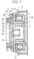
- a drive pulley 1 is rotated by power transmitted from a vehicle engine through a multi-V-belt (not shown).
- the pulley 1 is made of ferrous metal and is integrally formed with a groove portion 1a which has a plurality of V-grooves for engaging with the multi-in-belt.
- a drive rotor 2 is made of ferrous metal and is formed into a double cylinder having a U-shaped cross-section.
- the rotor 2 is connected to the pulley 1 by welding or other appropriate methods.
- Several bearings 3 are disposed at an inner side of the drive rotor 2.
- the rotor 2 is held by the bearings 3 on a cylindrical protruding portion of a front housing of a compressor (not shown) so that the rotor 2 can rotate freely.
- the compressor is used for compressing refrigerant in a refrigerant cycle of a vehicle air conditioner.
- a coil housing 4 is made of ferrous metal and is formed into a double cylinder having a U-shaped cross-section for accommodating an electromagnetic coil 5.
- the coil housing 4 operates as a stationary magnetic pole member.
- the coil housing 4 has an inner cylinder portion 4a and an outer cylinder portion 4b.
- the magnetic coil 5 is inserted into a housing space 4d of the coil housing 4 formed between the inner cylinder portion 4a and the outer cylinder portion 4b, and is secured in and insulated from the coil housing 4 by a resin member 6, which fills the housing space 4d of the coil housing 4.
- the resin member 6 is formed of resin material which can be formed at a relatively low temperature (i.e., 130-140 °C), such as epoxy resin or unsaturated polyester resin.
- the coil housing 4 is disposed in a housing space of the rotor 2 having a U-shaped cross-section to provide a small gap between the coil housing 4 and the rotor 2.
- a stay 7 made of ferrous metal and formed into a ring shape is connected to a bottom rear side of the coil housing 4 by spot welding or the like. The coil housing 4 is secured to the above-mentioned front housing of the compressor through the stay 7.
- the rotor 2 has a friction surface 2a extending in a radial direction of the rotor 2.
- the friction surface 2a has two magnetic blow-out grooves 2b, 2c formed into an arc shape extending along a periphery of the rotor 2.
- the magnetic blowout groove 2b is located at an outer peripheral side of the magnetic blow-out groove 2c.
- a friction member 2d is attached to the magnetic blow-out groove 2b to improve torque transmission.
- an armature 8 is made of ferrous metal and formed into a ring shape, and is disposed against the friction surface 2a of the rotor 2.
- the armature 8 is maintained a predetermined small distance away from the friction surface 2a by an elastic force of an elastic member 9, which will be described later.
- the armature 8 also has a magnetic blow-out groove 8a formed into an arc extending along a periphery of the armature 8.
- the armature 8 is secured to a ring-shaped holding member 11 made of ferrous metal, by means of a rivet 10 made of ferrous metal.
- the elastic member 9 is disposed between an inner surface of a cylinder portion 11a of the holding member 11 and an outer surface of an outer cylinder portion 12a of a hub 12, and is integrally formed with the holding member 11 and the hub 12 to be connected thereto. Thus, the elastic member 9 is disposed between the holding member 11 and the hub 12.
- the elastic member 9 has a cylindrical shape.
- the elastic member 9 is made of rubber which is excellent in torque transmission and in absorption of torque fluctuation within a temperature range of -30 to 120 °C, in which an ordinary vehicle can be used.
- chlorinated butyl rubber, acrylnitrile-butadiene rubber and ethylene propylene rubber are suitable as the material of the elastic member 9.
- the hub 12 is made of ferrous metal.
- a shaft (not shown) of the compressor is fit into a center cylinder 12b of the hub 12 using a spline or the like, and is secured to the hub 12 by a bolt (not shown).
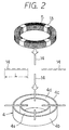
- the electromagnetic coil 5 is constructed from a large number of wire windings formed into an annular shape.
- An adhesive-type insulating tape made of paper is wound around the coil 5 as a coil holder 13 at a plurality of points along the circumference of the coil 5 to maintain the coil shape.
- the coil holder 13 is wound around the coil 5 at four points, as shown in FIG. 2.
- Paper string-like insulating members 14 are placed on an open end 4c of the coil housing 4 in such a manner that one of the insulating members 14 is located between each of the coil holders 13. Each insulating member 14 is easily deformed because it is made of paper.
- the coil 5 is placed so that it contacts the middle portion of each insulating member 14.
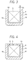
- each of the insulating members 14 is pressed downwardly by the coil 5 and deformed according to an inner shape of the coil housing 4 or a shape of the coil 5, and is nested between the coil housing 4 and the coil 5.
- FIG. 3 shows a state in which the coil 5 and the insulating members 14 are accommodated in the coil housing 4.
- Each string-like insulating member 14 preferably has a circular cross-section with a diameter of approximately 2.5 mm, for example. As shown in FIG. 3, the diameter of the circular cross-section of the insulating member 14 is determined so that a preset gap A is formed between the surface of the coil 5 and the inner surface of the coil housing 4 when the insulating members 14 and the coil 5 are accommodated in the annular housing space 4d of the coil housing 4. A longitudinal length L of the insulating member 14 is determined so that the insulating member 14 spans the entire peripheral surface of the coil 5 in the gap A, as shown in FIG. 3.
- the gap A can be formed by the insulating members 14 disposed on the coil 5 at four points along the circumference of the magnetic coil 5. Further, each of the insulating members 4 is located between each of the coil holders 13 which maintain the coil 5 as a unit. Therefore, the coil holders 13 can also contribute to form the gap A. Thus, the gap A is accurately formed even if the annular shape of the coil 5 is slightly deformed.
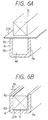
- the housing space 4d of the coil housing 4 is filled with the melted material of the resin member 6 from the open end 4c, as shown in FIG. 4.
- the melted material of the resin member 6 spreads across the surface of the coil 5 through the gap A. Further, the melted material of the resin member 6 penetrates the coil holders 13 and the insulating members 14 because both of the coil holders 13 and the insulating members 14 are made of paper.
- the resin member 6 affixes the coil 5 and insulates the surface of the coil 5 from the inner surface of the coil housing 4.
- the gap A between the coil 5 and the coil housing 4 is formed by the insulating members 14 inserted into the housing space 4d of the coil housing 4 and deformed by the coil 5. Therefore, the need for winding an adhesive-type thin insulating tape around the coil 5 to form the gap A is eliminated, thereby decreasing the time needed to attach the coil 5 to the coil housing 4. Furthermore, the paper insulating member 14 is less expensive than the adhesive-type thin insulating tape. Therefore, the cost of material of the electromagnetic clutch also can be decreased.
- the rotor 2 and the armature 8 rotate as a unit, and the rotation of the armature 8 is transmitted to the hub 12 through the rivet 10, the holding member 11 and the elastic member 9. Since the shaft of the compressor is integrally connected to the hub 12, the rotation of the pulley 1 is eventually transmitted to the shaft of the compressor, and the compressor starts operation.
- the elastic member 9 is also used to absorb torque fluctuation caused by the compressor during normal operation of the compressor.
- FIGS. 5, 6A and 6B A second embodiment of the present invention will be described with reference to FIGS. 5, 6A and 6B.
- components which are substantially the same as those in previous embodiments are assigned the same reference numerals.
- an insulating string made of paper is used as the insulating member 14.
- an insulating sheet made of, for example, cotton cloth and formed into a ring shape is used as an insulating member 214.
- the insulating member 214 can be readily deformed, and is penetrable by the material of the resin member 6.
- an inner circumference of the insulating member 214 has four slits 14a so that deformation in the vicinity of the inner circumference of the insulating member 214 is facilitated.
- the insulating member 214 is placed on the open end 4c of the coil housing 4, and the electromagnetic coil 5 is placed over the insulating member 214. Then, the coil 5 is inserted into the housing space 4d of the coil housing 4 together with the insulating member 214, while the insulating member 214 is pressed at a middle part of the insulating member 214 in a radial direction by the coil 5. As a result, the coil 5 and the insulating member 14 are accommodated in the housing space 4d of the coil housing 4, as shown in FIG. 6B.
- the insulating member 214 has a thickness of approximately 0.2-0.3 mm. However, the thickness of the insulating member 214 is determined so that a preset gap A is formed between the surface of the coil 5 and the inner surface of the coil housing 4 when the coil 5 and the insulating member 214 are accommodated in the housing space 4d of the coil housing 4, as shown in FIG. 6B. Further, outer and inner diameters of the insulating member 214 are determined so that the insulating member 214 covers the entire surface of the coil 5 in the gap A. After inserting the coil 5 and the insulating member 214 into the coil housing 4, the housing space 4d of the coil housing 4 is filled with the melted material of the resin member 6, from the open end 4d.
- the need to wind a thin insulating tape around the magnetic coil 5 to form a preset gap between the coil 5 and the coil chousing 4 is eliminated, resulting in an improved coil attachment efficiency.
- the insulating member 214 covers the entire circumference of the gap A because the insulating member 214 is a sheet. This further ensures insulation of the coil 5.
- the insulating member 214 is a flat sheet.
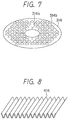
- an insulating sheet having a plurality of protrusions 14b on one surface of the sheet is used as an insulating member 314, as shown in FIG. 7.
- the width of the gap A between the electromagnetic coil 5 and the coil housing 4 can be made larger than the original thickness of the insulating member 314.
- insulating strings are used as the insulating members 14.
- corrugated insulating members having a rectangular shape are used as insulating members 414. According to the fourth embodiment, owing to the corrugated-shape of the insulating members 414, the width of the gap A can be made larger than the original thickness of the insulating member 414.
- each of the insulating members 214, 314 is formed into a single ring-like sheet, having enough surface area to cover the entire opening area of the open end 4c of the coil housing 4.
- each of the insulating members 214, 314 may alternatively be formed into a plurality of sheets formed into an arc shape, partially covering the open end 4c.
- the insulating members 14, 214, 314 and 414 are made of paper or cotton cloth.
- the insulating members 14, 214, 314 and 414 may also be made of glass fiber, felt, rubber, synthetic fiber or porous material such as polyurethane form.
- the insulating members 14, 214, 314 and 414 may be made of any material that can be easily deformed and that is penetrable by the material of the resin member 6.
- the electromagnetic clutch is used for a compressor in a vehicle air conditioner; however, the present invention may also be applied to electromagnetic clutches in various use.
Landscapes
- Engineering & Computer Science (AREA)
- General Engineering & Computer Science (AREA)
- Mechanical Engineering (AREA)
- Physics & Mathematics (AREA)
- Electromagnetism (AREA)
- Electromagnets (AREA)
Applications Claiming Priority (3)
| Application Number | Priority Date | Filing Date | Title |
|---|---|---|---|
| JP25228997 | 1997-09-17 | ||
| JP25228997A JP3887906B2 (ja) | 1997-09-17 | 1997-09-17 | 電磁クラッチの製造方法 |
| JP252289/97 | 1997-09-17 |
Publications (3)
| Publication Number | Publication Date |
|---|---|
| EP0903512A2 true EP0903512A2 (de) | 1999-03-24 |
| EP0903512A3 EP0903512A3 (de) | 2000-03-01 |
| EP0903512B1 EP0903512B1 (de) | 2003-06-18 |
Family
ID=17235194
Family Applications (1)
| Application Number | Title | Priority Date | Filing Date |
|---|---|---|---|
| EP98117595A Expired - Lifetime EP0903512B1 (de) | 1997-09-17 | 1998-09-16 | Elektromagnetische Kupplung |
Country Status (4)
| Country | Link |
|---|---|
| US (1) | US6138809A (de) |
| EP (1) | EP0903512B1 (de) |
| JP (1) | JP3887906B2 (de) |
| DE (1) | DE69815612T2 (de) |
Cited By (1)
| Publication number | Priority date | Publication date | Assignee | Title |
|---|---|---|---|---|
| FR2798973A1 (fr) * | 1999-09-27 | 2001-03-30 | Tractech Inc | Embrayage electrique comprenant des moyens de rappels a disque flexible |
Families Citing this family (9)
| Publication number | Priority date | Publication date | Assignee | Title |
|---|---|---|---|---|
| JP2002295716A (ja) * | 2001-03-29 | 2002-10-09 | Toyota Motor Corp | 電磁駆動バルブ |
| US7090063B2 (en) * | 2002-02-12 | 2006-08-15 | Valeo Thermal Systems Japan Corporation | Electromagnetic clutch |
| US6916161B2 (en) * | 2002-08-09 | 2005-07-12 | John R. Brunner | System, method, and apparatus for shielding sparks originating from a compressor in a marine air conditioner |
| JP4255741B2 (ja) * | 2003-04-24 | 2009-04-15 | 本田技研工業株式会社 | 電磁コイルアセンブリ及び電磁アクチュエータ |
| KR100659223B1 (ko) * | 2006-05-25 | 2006-12-19 | 쓰리에이기계(주) | 마그네틱 클러치 풀리 |
| US8015849B2 (en) * | 2007-10-08 | 2011-09-13 | American Trim, Llc | Method of forming metal |
| US7982133B2 (en) * | 2008-08-29 | 2011-07-19 | Pratt & Whitney Canada Corp. | Crack controlled resin insulated electrical coil |
| PL2465120T3 (pl) * | 2009-08-11 | 2014-06-30 | Litens Automotive Inc | Elektromagnes i zespół cewki elektromagnetycznej |
| WO2023248941A1 (ja) * | 2022-06-23 | 2023-12-28 | 株式会社ヴァレオジャパン | 電磁コイル、この電磁コイルを備えた電磁クラッチ、及びこの電磁コイルの製造方法 |
Family Cites Families (12)
| Publication number | Priority date | Publication date | Assignee | Title |
|---|---|---|---|---|
| US1880821A (en) * | 1930-06-23 | 1932-10-04 | Inca Mfg Corp | Coil |
| US2385460A (en) * | 1943-02-15 | 1945-09-25 | Jefferson Electric Co | Method of insulating electrical apparatus |
| US2602035A (en) * | 1949-09-08 | 1952-07-01 | Gen Electric | Paper pulp coating of coils |
| US3088174A (en) * | 1959-01-28 | 1963-05-07 | Gen Motors Corp | Method of producing a reinforced plastic die |
| JPS5839257B2 (ja) * | 1979-01-08 | 1983-08-29 | 株式会社日立製作所 | 電磁クラツチ |
| US4935713A (en) * | 1989-06-12 | 1990-06-19 | Ford Motor Company | Field coil assembly for an electromagnetically actuated clutch |
| DE9003343U1 (de) * | 1990-03-21 | 1990-05-23 | Herion-Werke GmbH & Co. KG, 70736 Fellbach | Vergußgekapselte Vorrichtung |
| JP2566289Y2 (ja) * | 1991-05-28 | 1998-03-25 | 株式会社デンソー | 圧縮機用電磁クラッチ |
| US5232076A (en) * | 1992-05-19 | 1993-08-03 | Nippondenso Co., Ltd. | Electromagnetic clutch |
| JPH07224861A (ja) * | 1993-08-31 | 1995-08-22 | Nippondenso Co Ltd | 電磁クラッチ |
| US5756028A (en) * | 1994-08-23 | 1998-05-26 | Liao; Ju-Liang | Method of manufacturing resin articles having a naturally formed pattern thereon |
| JP2770938B2 (ja) * | 1995-03-08 | 1998-07-02 | サンデン株式会社 | 電磁装置 |
-
1997
- 1997-09-17 JP JP25228997A patent/JP3887906B2/ja not_active Expired - Fee Related
-
1998
- 1998-08-13 US US09/133,648 patent/US6138809A/en not_active Expired - Lifetime
- 1998-09-16 DE DE69815612T patent/DE69815612T2/de not_active Expired - Lifetime
- 1998-09-16 EP EP98117595A patent/EP0903512B1/de not_active Expired - Lifetime
Cited By (1)
| Publication number | Priority date | Publication date | Assignee | Title |
|---|---|---|---|---|
| FR2798973A1 (fr) * | 1999-09-27 | 2001-03-30 | Tractech Inc | Embrayage electrique comprenant des moyens de rappels a disque flexible |
Also Published As
| Publication number | Publication date |
|---|---|
| EP0903512A3 (de) | 2000-03-01 |
| JP3887906B2 (ja) | 2007-02-28 |
| US6138809A (en) | 2000-10-31 |
| JPH1182552A (ja) | 1999-03-26 |
| DE69815612D1 (de) | 2003-07-24 |
| EP0903512B1 (de) | 2003-06-18 |
| DE69815612T2 (de) | 2004-05-13 |
Similar Documents
| Publication | Publication Date | Title |
|---|---|---|
| EP0903512B1 (de) | Elektromagnetische Kupplung | |
| EP0741254B1 (de) | Spulenanordnung für elektromagnetische Vorrichtung | |
| US4432446A (en) | Electromagnetic coupling apparatus | |
| EP0821176B1 (de) | Elektromagnetische Kupplungsvorrichtung | |
| US5508671A (en) | Electromagnetic coupling device | |
| US5551546A (en) | Electromagnetic clutch | |
| JP3837786B2 (ja) | 電磁クラッチ | |
| JPH08326782A (ja) | 電磁クラッチ | |
| US4808870A (en) | Electromagnetic clutch with impact absorbing connector | |
| US5952908A (en) | Coil bobbin and an exciting coil assembly | |
| EP0422962B1 (de) | Elektromagnetische Kupplung | |
| US6169347B1 (en) | Rotating coil electromagnetic clutch | |
| EP0086443B1 (de) | Generator vom Typ mit feststehender Felderregerspule und ein Verfahren zu dessen Herstellung | |
| EP0428403B1 (de) | Elektromagnetische Kupplungsvorrichtung | |
| US5996759A (en) | Coil-rotation type electromagnetic clutch | |
| JP3605876B2 (ja) | 動力断続機 | |
| US3833871A (en) | Coil connections for an electromagnetic drive | |
| US4892176A (en) | Electromagnetic clutch having high torque transfer | |
| US7213695B2 (en) | Electromagnetic clutch | |
| CN100582350C (zh) | 转筒式洗衣机的外转子式马达的定子 | |
| KR960013937B1 (ko) | 조립이 간단한 구조의 전자 클러치 | |
| JP2663364B2 (ja) | 電磁連結装置 | |
| JP2001317564A (ja) | 電磁クラッチ用ヨーク | |
| CN118431852B (zh) | 导电刷、导电环、电机、汽车及该导电刷的制备方法 | |
| KR100658989B1 (ko) | 압축기의전자클러치 |
Legal Events
| Date | Code | Title | Description |
|---|---|---|---|
| PUAI | Public reference made under article 153(3) epc to a published international application that has entered the european phase |
Free format text: ORIGINAL CODE: 0009012 |
|
| AK | Designated contracting states |
Kind code of ref document: A2 Designated state(s): DE FR IT |
|
| AX | Request for extension of the european patent |
Free format text: AL;LT;LV;MK;RO;SI |
|
| PUAL | Search report despatched |
Free format text: ORIGINAL CODE: 0009013 |
|
| AK | Designated contracting states |
Kind code of ref document: A3 Designated state(s): AT BE CH CY DE DK ES FI FR GB GR IE IT LI LU MC NL PT SE |
|
| AX | Request for extension of the european patent |
Free format text: AL;LT;LV;MK;RO;SI |
|
| 17P | Request for examination filed |
Effective date: 20000207 |
|
| AKX | Designation fees paid |
Free format text: DE FR IT |
|
| 17Q | First examination report despatched |
Effective date: 20020416 |
|
| GRAH | Despatch of communication of intention to grant a patent |
Free format text: ORIGINAL CODE: EPIDOS IGRA |
|
| GRAH | Despatch of communication of intention to grant a patent |
Free format text: ORIGINAL CODE: EPIDOS IGRA |
|
| GRAA | (expected) grant |
Free format text: ORIGINAL CODE: 0009210 |
|
| AK | Designated contracting states |
Designated state(s): DE FR IT |
|
| REF | Corresponds to: |
Ref document number: 69815612 Country of ref document: DE Date of ref document: 20030724 Kind code of ref document: P |
|
| ET | Fr: translation filed | ||
| PLBE | No opposition filed within time limit |
Free format text: ORIGINAL CODE: 0009261 |
|
| STAA | Information on the status of an ep patent application or granted ep patent |
Free format text: STATUS: NO OPPOSITION FILED WITHIN TIME LIMIT |
|
| 26N | No opposition filed |
Effective date: 20040319 |
|
| PGFP | Annual fee paid to national office [announced via postgrant information from national office to epo] |
Ref country code: FR Payment date: 20080915 Year of fee payment: 11 |
|
| PGFP | Annual fee paid to national office [announced via postgrant information from national office to epo] |
Ref country code: IT Payment date: 20080927 Year of fee payment: 11 |
|
| REG | Reference to a national code |
Ref country code: FR Ref legal event code: ST Effective date: 20100531 |
|
| PG25 | Lapsed in a contracting state [announced via postgrant information from national office to epo] |
Ref country code: FR Free format text: LAPSE BECAUSE OF NON-PAYMENT OF DUE FEES Effective date: 20090930 |
|
| PG25 | Lapsed in a contracting state [announced via postgrant information from national office to epo] |
Ref country code: IT Free format text: LAPSE BECAUSE OF NON-PAYMENT OF DUE FEES Effective date: 20090916 |
|
| PGFP | Annual fee paid to national office [announced via postgrant information from national office to epo] |
Ref country code: DE Payment date: 20140922 Year of fee payment: 17 |
|
| REG | Reference to a national code |
Ref country code: DE Ref legal event code: R119 Ref document number: 69815612 Country of ref document: DE |
|
| PG25 | Lapsed in a contracting state [announced via postgrant information from national office to epo] |
Ref country code: DE Free format text: LAPSE BECAUSE OF NON-PAYMENT OF DUE FEES Effective date: 20160401 |