EP0903511B1 - Biegsame Platte und Schwungradgestaltung - Google Patents
Biegsame Platte und Schwungradgestaltung Download PDFInfo
- Publication number
- EP0903511B1 EP0903511B1 EP98123586A EP98123586A EP0903511B1 EP 0903511 B1 EP0903511 B1 EP 0903511B1 EP 98123586 A EP98123586 A EP 98123586A EP 98123586 A EP98123586 A EP 98123586A EP 0903511 B1 EP0903511 B1 EP 0903511B1
- Authority
- EP
- European Patent Office
- Prior art keywords
- flywheel
- flexible plate
- crankshaft
- plate
- support portion
- Prior art date
- Legal status (The legal status is an assumption and is not a legal conclusion. Google has not performed a legal analysis and makes no representation as to the accuracy of the status listed.)
- Expired - Lifetime
Links
- 230000002093 peripheral effect Effects 0.000 claims description 42
- 238000005452 bending Methods 0.000 claims description 34
- 230000005540 biological transmission Effects 0.000 description 7
- 238000013016 damping Methods 0.000 description 6
- 230000001133 acceleration Effects 0.000 description 5
- 238000002485 combustion reaction Methods 0.000 description 4
- 230000002159 abnormal effect Effects 0.000 description 3
- 230000006866 deterioration Effects 0.000 description 3
- 239000002184 metal Substances 0.000 description 3
- 230000001151 other effect Effects 0.000 description 2
- 230000000712 assembly Effects 0.000 description 1
- 238000000429 assembly Methods 0.000 description 1
- 238000011161 development Methods 0.000 description 1
- 230000018109 developmental process Effects 0.000 description 1
- 230000000694 effects Effects 0.000 description 1
- 238000003754 machining Methods 0.000 description 1
- 238000013021 overheating Methods 0.000 description 1
Images


Classifications
-
- F—MECHANICAL ENGINEERING; LIGHTING; HEATING; WEAPONS; BLASTING
- F16—ENGINEERING ELEMENTS AND UNITS; GENERAL MEASURES FOR PRODUCING AND MAINTAINING EFFECTIVE FUNCTIONING OF MACHINES OR INSTALLATIONS; THERMAL INSULATION IN GENERAL
- F16F—SPRINGS; SHOCK-ABSORBERS; MEANS FOR DAMPING VIBRATION
- F16F15/00—Suppression of vibrations in systems; Means or arrangements for avoiding or reducing out-of-balance forces, e.g. due to motion
- F16F15/10—Suppression of vibrations in rotating systems by making use of members moving with the system
- F16F15/12—Suppression of vibrations in rotating systems by making use of members moving with the system using elastic members or friction-damping members, e.g. between a rotating shaft and a gyratory mass mounted thereon
- F16F15/131—Suppression of vibrations in rotating systems by making use of members moving with the system using elastic members or friction-damping members, e.g. between a rotating shaft and a gyratory mass mounted thereon the rotating system comprising two or more gyratory masses
- F16F15/13142—Suppression of vibrations in rotating systems by making use of members moving with the system using elastic members or friction-damping members, e.g. between a rotating shaft and a gyratory mass mounted thereon the rotating system comprising two or more gyratory masses characterised by the method of assembly, production or treatment
- F16F15/1315—Multi-part primary or secondary masses, e.g. assembled from pieces of sheet steel
-
- F—MECHANICAL ENGINEERING; LIGHTING; HEATING; WEAPONS; BLASTING
- F16—ENGINEERING ELEMENTS AND UNITS; GENERAL MEASURES FOR PRODUCING AND MAINTAINING EFFECTIVE FUNCTIONING OF MACHINES OR INSTALLATIONS; THERMAL INSULATION IN GENERAL
- F16D—COUPLINGS FOR TRANSMITTING ROTATION; CLUTCHES; BRAKES
- F16D13/00—Friction clutches
- F16D13/58—Details
- F16D13/70—Pressure members, e.g. pressure plates, for clutch-plates or lamellae; Guiding arrangements for pressure members
-
- F—MECHANICAL ENGINEERING; LIGHTING; HEATING; WEAPONS; BLASTING
- F16—ENGINEERING ELEMENTS AND UNITS; GENERAL MEASURES FOR PRODUCING AND MAINTAINING EFFECTIVE FUNCTIONING OF MACHINES OR INSTALLATIONS; THERMAL INSULATION IN GENERAL
- F16D—COUPLINGS FOR TRANSMITTING ROTATION; CLUTCHES; BRAKES
- F16D3/00—Yielding couplings, i.e. with means permitting movement between the connected parts during the drive
- F16D3/50—Yielding couplings, i.e. with means permitting movement between the connected parts during the drive with the coupling parts connected by one or more intermediate members
- F16D3/76—Yielding couplings, i.e. with means permitting movement between the connected parts during the drive with the coupling parts connected by one or more intermediate members shaped as an elastic ring centered on the axis, surrounding a portion of one coupling part and surrounded by a sleeve of the other coupling part
- F16D3/77—Yielding couplings, i.e. with means permitting movement between the connected parts during the drive with the coupling parts connected by one or more intermediate members shaped as an elastic ring centered on the axis, surrounding a portion of one coupling part and surrounded by a sleeve of the other coupling part the ring being metallic
-
- F—MECHANICAL ENGINEERING; LIGHTING; HEATING; WEAPONS; BLASTING
- F16—ENGINEERING ELEMENTS AND UNITS; GENERAL MEASURES FOR PRODUCING AND MAINTAINING EFFECTIVE FUNCTIONING OF MACHINES OR INSTALLATIONS; THERMAL INSULATION IN GENERAL
- F16F—SPRINGS; SHOCK-ABSORBERS; MEANS FOR DAMPING VIBRATION
- F16F15/00—Suppression of vibrations in systems; Means or arrangements for avoiding or reducing out-of-balance forces, e.g. due to motion
- F16F15/10—Suppression of vibrations in rotating systems by making use of members moving with the system
- F16F15/12—Suppression of vibrations in rotating systems by making use of members moving with the system using elastic members or friction-damping members, e.g. between a rotating shaft and a gyratory mass mounted thereon
- F16F15/131—Suppression of vibrations in rotating systems by making use of members moving with the system using elastic members or friction-damping members, e.g. between a rotating shaft and a gyratory mass mounted thereon the rotating system comprising two or more gyratory masses
- F16F15/13107—Suppression of vibrations in rotating systems by making use of members moving with the system using elastic members or friction-damping members, e.g. between a rotating shaft and a gyratory mass mounted thereon the rotating system comprising two or more gyratory masses for damping of axial or radial, i.e. non-torsional vibrations
-
- F—MECHANICAL ENGINEERING; LIGHTING; HEATING; WEAPONS; BLASTING
- F16—ENGINEERING ELEMENTS AND UNITS; GENERAL MEASURES FOR PRODUCING AND MAINTAINING EFFECTIVE FUNCTIONING OF MACHINES OR INSTALLATIONS; THERMAL INSULATION IN GENERAL
- F16F—SPRINGS; SHOCK-ABSORBERS; MEANS FOR DAMPING VIBRATION
- F16F15/00—Suppression of vibrations in systems; Means or arrangements for avoiding or reducing out-of-balance forces, e.g. due to motion
- F16F15/10—Suppression of vibrations in rotating systems by making use of members moving with the system
- F16F15/12—Suppression of vibrations in rotating systems by making use of members moving with the system using elastic members or friction-damping members, e.g. between a rotating shaft and a gyratory mass mounted thereon
- F16F15/131—Suppression of vibrations in rotating systems by making use of members moving with the system using elastic members or friction-damping members, e.g. between a rotating shaft and a gyratory mass mounted thereon the rotating system comprising two or more gyratory masses
- F16F15/13142—Suppression of vibrations in rotating systems by making use of members moving with the system using elastic members or friction-damping members, e.g. between a rotating shaft and a gyratory mass mounted thereon the rotating system comprising two or more gyratory masses characterised by the method of assembly, production or treatment
-
- F—MECHANICAL ENGINEERING; LIGHTING; HEATING; WEAPONS; BLASTING
- F16—ENGINEERING ELEMENTS AND UNITS; GENERAL MEASURES FOR PRODUCING AND MAINTAINING EFFECTIVE FUNCTIONING OF MACHINES OR INSTALLATIONS; THERMAL INSULATION IN GENERAL
- F16H—GEARING
- F16H41/00—Rotary fluid gearing of the hydrokinetic type
- F16H41/24—Details
Definitions
- the present invention relates to a flywheel assembly, and in particular to a flywheel assembly having a flexible plate for damping a bending vibration transmitted from a crankshaft of an engine.
- Combustion energy from an engine is converted into a torque by the arrangement of a crankshaft in the engine in a manner well known in the art.
- the torque is transmitted to a flywheel, and is further transmitted to a transmission via a clutch.
- the combustion process within the engine is such that the energy transmitted to the crankshaft exerts a bending force on the crankshaft. Bending of the crankshaft causes a vibration of a flywheel attached to an end of the crankshaft. A counter-force thereof is transmitted to an engine block, and is further transmitted to a body of a vehicle via an engine mount to vibrate the body. This causes noises during acceleration of the vehicle.
- flywheel assemblies have also been employed that are coupled to an end of a crankshaft via a flexible plate.
- the flexible plate has a high rigidity in the rotating direction (or circumferential direction) and a predetermined flexibility in the bending direction (or generally axial directions).
- the flywheel body is carried by the crankshaft only via the flexible plate. Therefore, it may rotate in an imbalance state when the flywheel itself is inclined with respect to its rotation axis due to bending forces.
- a lower rigidity of the flexible plate can reduce the bending vibration more effectively. Particularly, it is possible to shift a resonance point from a practical operation region by reducing the rigidity of the flexible plate, and thereby noises during acceleration of the engine can be further reduced.
- the operation of a clutch usually requires a force to be exerted on the clutch assembly to disengage the clutch from transmitting torque.
- the disengaging force is applied in a direction that is ultimately exerted on the crankshaft of the engine.
- the disengaging force is generally axially oriented and is applied to a clutch assembly.
- the force, or release load is then transmitted to the flywheel and the flex plate and further transmitted to the crankshaft of the flywheel. Consequently, if the rigidity of the flex plate in the axial or bending direction were excessively low, the flywheel would axially move toward the crankshaft an excessive extent during the clutch release operation, which would reduce a disengaging efficiency of the clutch.
- DE 44 02 257 A1 describes a flywheel assembly comprising a flexible plate having flexibility in a bending direction, and an inner peripheral portion fixed to a crankshaft. A flywheel is fixed to the flexible plate. Further, a plurality of fixing members are arranged for fixing the flexible plate to the crankshaft.
- EP 0 475 366 A2 describes an automotive power train.
- an annular resilient disc interconnects a crankshaft and an annular flywheel.
- the crankshaft has an axially extended cylindrical wall in opposed and spaced relationship to an inner peripheral wall of the annular flywheel.
- an elastic annular body has an inner peripheral wall fixed to the crankshaft and an outer peripheral wall opposed to the inner peripheral wall of the flywheel.
- a heat insulating ring or heat insulating pieces are provided to reduce transmission heat from the flywheel to the elastic annular body.
- a heat insulating space or spaces may be provided.
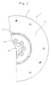
- Figs. 1 and 2 show a flywheel assembly 1.
- the flywheel assembly 1 is provided for transmitting a torque from a crankshaft 100 of an engine to a clutch apparatus (not shown).
- O-O represents a rotation axis of the flywheel assembly 1.
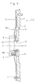
- the flywheel assembly 1 is attached to an end of the crankshaft 100, and is basically formed of a flexible plate 3 and a flywheel 2.
- the flexible plate 3 is made of a circular metal sheet. An inner peripheral portion of the flexible plate 3 is fixed to an end of the crankshaft 100 by bolts 5. An annular member 6 is interposed between heads of the bolts 5 and an inner peripheral portion of the flexible plate 3. An outer peripheral portion of the flexible plate 3 is fixed to an outer peripheral portion of the flywheel 2 by a plurality of bolts 4.
- the flexible plate 3 has a high rigidity in the rotation direction but is flexible and elastically deformable in the bending direction.
- the flexible plate 3 is provided at its inner periphery with a cylindrical support portion 16 extending away from the engine, i.e., toward the flywheel 2.
- the flexible plate 3 is provided with a drawn portion 17 which is located radially outside the bolts 5 and projects toward the flywheel 2.
- the drawn portion 17 has an annular form. As shown in Fig. 4, the drawn portion 17 has a plurality of extruded portions 18 extending in the circumferential direction. The extruded portions 18 project toward the flywheel 2 and have
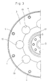
- the flexible plate 3 is provided at its radially middle portion with eight circular holes 19 which are circumferentially equally spaced from each other, as shown in Fig. 3. Bending characteristics of the flexible plate 3 can be changed by changing the number, size, position, configuration and others of the circular holes 19.
- the flywheel 2 is made of a substantially circular cast member.
- the flywheel 2 is provided at its radially outer portion with a friction surface 11, which is opposed to the transmission and is to be pressed against a friction facing (not shown) of a clutch disk assembly of the clutch apparatus.
- the flywheel 2 is provided with air holes 12 which are located radially inside the friction surface 11 and axially extend through the flywheel 2.
- Each air hole 12 extends in the circumferential direction of the flywheel 2, and has a section diverging toward the engine.
- the air holes 12 are formed correspondingly to the circular holes 19 of the flexible plate 3, respectively.
- the flywheel 2 is further provided at a portion radially inside the air holes 12 with bolt head escape holes 14 for avoiding interference with heads of the bolts 5.
- the flywheel 2 is provided at its inner peripheral portion with a cylindrical portion 13 extending toward the engine.
- the cylindrical portion 13 is loosely fitted into the cylindrical support portion 16. Therefore, the outer peripheral surface of the cylindrical portion 13 is in contact with or slightly spaced from the inner peripheral surface of the cylindrical support portion 16. This improves an accuracy of centering between these members.
- the cylindrical portion 13 has a spherical outer peripheral surface, it may have a cylindrical outer peripheral surface which is in contact with the cylindrical support portion 16 without a gap.
- the flywheel 2 has an annular contact portion 15, which corresponds to the extruded portions 18 formed at the drawn portion 17, as shown in Figs. 1 and 4.
- the crankshaft 100 receives a bending vibration due to a combustion force of the engine.
- this bending vibration is transmitted to the flexible plate 3
- the flexible plate 3 bends in the bending direction to cause frictional sliding between the cylindrical support portion 16 and the cylindrical portion 13, so that the bending vibration is rapidly damped.
- the flexible plate 3 bends only to a small extent, the flexible plate 3 entirely bends, so that it exhibits a low rigidity.
- the flexible plate 3 is thin and has the circular holes 19, so that it has a low rigidity.
- the flexible plate 3 bends to a large extent, the extruded portions 18 formed at the drawn portion 17 are partially brought into contact with the contact portion 15 of the flywheel 2. Thereafter, the flexible plate 3 bends around the contact portion 15, and exhibits a high rigidity. Owing to provision of the drawn portion 17, a portion of the flexible plate 3 which bends to the highest extent is shifted radially outward compared with a conventional structure, so that a stress is effectively dispersed radially outward compared with the conventional structure. This increases a life-time of the flexible plate 3.
- a release load acts on the flywheel 2. This moves the flywheel 2 toward the engine. Thereby, the contact portion 15 is brought into the extruded portions 18 formed at the drawn portion 17. Thereafter, the release load is transmitted from the flywheel 2 to the crankshaft 100 via the drawn portion 17. In this manner, axial movement of the flywheel 2 is significantly restricted, so that the disengaging efficiency of the clutch is improved. Further, the crankshaft can directly bear the release load, so that the flexible plate 3 can be thin. Consequently, the flexible plate 3 can have an improved function of damping the bending vibration.
- the cylindrical support portion 16 of the flexible plate 3 restricts the radial movement of the rotating flywheel 2, deflective rotation which may be caused by imbalance can be suppressed. Consequently, a vibration due to the deflective rotation can be suppressed. Further, if a radially inner portion of the flexible plate 3 should be cut or broken in the vicinity of the bolts 5, the flywheel 2 will be supported by the cylindrical support portion 16, and thus will be prevented from radially disengaging the crankshaft 100.
- the flywheel 2 Since the cylindrical support portion 16 and the cylindrical portion 13 are friction fitted together such that they slide with respect to one another, the flywheel 2 has an improved accuracy of centering with respect to the flexible plate 3.
- the flywheel assembly when a release load acts on the flywheel, the flywheel moves a predetermined distance, and then is brought into contact with the drawn portion of the flexible plate. Thereby, the flywheel is supported by the crankshaft via the projection of the flexible plate. Since the projection restricts the axial movement of the flywheel in this manner, reduction in disengaging efficiency of the clutch can be prevented.
- the flexible plate is provided at its circular plate body with the drawn portion, stress concentrations in the flexible plate are dispersed, so that portions of the flexible plate other than the drawn portion can have a reduced thickness while suppressing breakage thereof.
- the portion radially outside the drawn portion can have a reduced rigidity.
- the drawn portion projects toward the flywheel to ensure a gap between the drawn portion and the flywheel, the drawn portion restricts the axial movement of the flywheel, so that reduction in disengaging efficiency of the clutch can be prevented.
- the flywheel is restricted from radially moving and inclining with respect to the flexible plate.
- a drawn portion such as the drawn portion 17 described in the first embodiment, is not formed at the flexible plate 30. Therefore, the flywheel 2 moves toward the engine and its inner peripheral portion is brought into contact with the end of the cylindrical support portion 16 of the flexible plate 30 when a release load acts on the flywheel 2. Thereafter, the release load is transmitted to the crankshaft 100 via the cylindrical support portion 16. Since the axial movement of the flywheel 2 is small as described above, the disengaging efficiency of the clutch is improved.
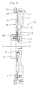
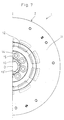
- Figs. 6, 7 and 8 show an other flywheel assembly 121.
- the flywheel assembly 121 is provided for transmitting a torque from a crankshaft 100 of an engine to a transmission (not shown) via a clutch apparatus.
- O-O represents a rotation axis of the flywheel assembly 121.
- the flywheel assembly 121 is attached to an end of the crankshaft 100, and includes a flywheel 2 and a flexible plate 35.
- the flexible plate 35 is made of, for instance, sheet metal. An inner peripheral portion of the flexible plate 35 is fixed to the crankshaft 100 by a plurality of bolts 5. An outer peripheral portion of the flexible plate 35 is fixed to the flywheel 2 by bolts 4.
- the flexible plate 35 is provided at its inner periphery with a cylindrical support portion 16' extending toward the transmission.
- the cylindrical support portion 16' has a corrugated form or section formed by drawing, as can be seen in Fig. 7, and portions of the cylindrical support portion 16' extend radially outward between the bolts 5. Portions of the cylindrical support portion 16' extend radially inward and have contact surfaces formed by cutting or machining. The contact surfaces of the support portion 16' engage a cylindrical portion 13 formed on the flywheel 2, as is explained in greater detail below.
- the flexible plate 35 is provided at its radially middle portion with a plurality of circular holes 19 which are circumferentially equally spaced from each other.
- the rigidity in the bending direction of the flexible plate 35 can be adjusted by changing the number and size of the circular holes 19.
- the flexible plate 35 is provided at its outer periphery with an outer cylindrical portion 38 extending toward the engine.
- a ring gear 20 is welded to the outer periphery of the outer cylindrical portion 38.
- the flywheel 2 is made of a substantially circular cast member.
- the flywheel 2 is provided at its radially outer portion with a friction surface 11, which is opposed to the transmission and is to be pressed against a friction facing (not shown) of a clutch disk assembly.
- the flywheel 2 is provided with air holes 12 which are located radially inside the friction surface 11.
- Each air hole 12 extends in the circumferential direction of the flywheel 2, and has a section diverging toward the engine.
- the air holes 12 are formed correspondingly to the circular holes 19, respectively.
- the flywheel 2 is further provided at its inner peripheral portion with bolt head escape holes 14 for avoiding interference with heads of the bolts 5.
- the flywheel 2 is provided at its inner periphery with a cylindrical portion 13 extending toward the engine. The cylindrical portion 13 is loosely fitted into the inner contact surfaces of the cylindrical support portion 16'. Since the flywheel 2 and the flexible plate 35 is centered each other in this manner, an additional member for centering can be eliminated.
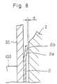
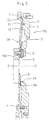
- a washer plate 8 is disposed between the inner peripheral portion of the flexible plate 35 and the inner peripheral portion of the flywheel 2.
- the washer plate 8 is in an annular form, and has an outer diameter larger than that of the end of the crankshaft 100.
- a radially outer portion 8a of the washer plate 8 is bent at a predetermined angle toward the flywheel 2, and the outer peripheral portion of this radially outer portion is bent to form a flat surface 8b parallel to the side surface of the flywheel 2.
- the washer plate 8 is provided at its outer peripheral portion with a plurality of radial slits which are circumferentially equally spaced from each other.
- the flexible plate 35 is formed with a plurality of protrusions 37 which extend between the slits.
- the washer plate 8 has a high rigidity in the clutch release operation direction (axial direction), and has a low rigidity in the bending direction.
- the radially outer portion 8a has the rigidity in the axial direction which is higher than that in the axial direction of the flexible plate 35.
- the washer plate 8 has an outer diameter larger than the outer diameter of the end of the crankshaft 100, whereby deformation of the flexible plate 35 is suppressed, and it is possible to disperse or distribute the maximum stress in the flexible plate 35, which may appear at its portion joined to the outer peripheral portion of the crankshaft 100. Since the washer plate 8 has the flat surface 8b at its radially outer end, the washer plate 8 is always brought into stable contact with the side surface of the flywheel 2 when a large bending vibration occurs. Therefore, it is possible to suppress change in magnitude of the contact friction over time.
- the flexible plate 35 and the flywheel 2 are arranged such that a gap D is formed between the cylindrical support portion 16' and the side surface of the flywheel 2.
- the flat surface 8b of the washer plate 8 is not in contact with the side surface of the flywheel 2, and thus a gap d (see Fig. 8) is ensured.
- the gap d is smaller than the gap D.
- the flexible plate 35 When the flexible plate 35 is bent only to a small extent, it provides low-rigidity characteristics depending on the initial loads of the flexible plate 35 and the washer plate 8. Particularly, a reduced thickness of the flexible plate 35 and provision of the circular holes 19 further reduce the rigidity.
- the flat surface 8b of the washer plate 8 is brought into contact with the side surface of the flywheel 2. Thereafter, the characteristics depend on the rigidity on the washer plate 8 in addition to the elastic characteristics of the flexible plate 35. Further, friction is caused by contact between the flat surface 8b of the washer plate 8 and the flywheel 2. This friction damps the bending vibration.
- a release load acts on the flywheel 2.
- the flywheel 2 moves, e.g., toward the engine, and thereby axially deforms the flexible plate 35.
- the flywheel 2 is then brought into contact with the washer plate 8 and thereby deforms the flexible plate 35 and the washer plate 8.
- the flywheel 2 is brought into contact with the cylindrical support portion 16' of the flexible plate 35.
- the release load of the flywheel 2 acts on the crankshaft 100 via the cylindrical support portion 16'.
- the cylindrical support portion 16' Since the cylindrical support portion 16' is formed by drawing, it has a generally high rigidity. Therefore, its radial thickness can be smaller than that in the prior art. Consequently, the cylindrical support portion 16' can be arranged at a small gap between the cylindrical portion 13 and the bolts 5. Further, the portions of the cylindrical support portion 16' which are shifted radially outward are located circumferentially between the bolts 5, so that the cylindrical support portion 16' can have a large diameter, and can be located at the same side as the bolts 5. In this manner, the cylindrical support portion 16' can be arranged in an optimum manner at a small space between the bolts 5 and the cylindrical portion 13.
- the flexible plate since the cylindrical support portion of the flexible plate radially overlaps the cylindrical portion of the flywheel, the flexible plate restricts radial movement and inclination of the flywheel. Consequently, rotation of the flywheel in an inclined state can be suppressed.
- the accuracy of centering between the flywheel and the flexible plate can be improved.
- the cylindrical portion and the cylindrical support portion are arranged to cause frictional sliding therebetween in accordance with relative movement between the flexible plate and the flywheel, the cylindrical portion and the cylindrical support portion frictionally slide on each other when the flywheel assembly receives the bending vibration, so that the bending vibration can be rapidly damped.
- the cylindrical support portion has the corrugated section formed by drawing, the cylindrical support portion has a higher rigidity, so that the radial thickness of the cylindrical support portion can be reduced.
- the cylindrical support portion has the inner peripheral surface forming the contact surface in contact with the outer peripheral surface the cylindrical portion, the accuracy of centering between the flexible plate and the flywheel is improved.
- the cylindrical support portion can be arranged closer to the fixing members, so that the space can be utilized efficiently.
- the cylindrical support portion 16' restricts the radial movement and inclination of the flywheel 2. Therefore, deflective rotation of the flywheel 2 in the inclined state can be suppressed. Further, even when the flexible plate 35 is cut or broken, the flywheel 2 will be supported by the cylindrical support portion 16', and thus will be suppressed from radially disengaging.
- the cylindrical support portion 16' Since the cylindrical support portion 16' is formed by drawing, it has a high rigidity. Therefore, its radial thickness can be small. Further, the portions of the cylindrical support portion which are shifted radially outward are arranged circumferentially between the bolts 5, so that the cylindrical support portion 16' having a large diameter can be arranged close to the bolts 5. In this manner, the cylindrical support portion 16' can be arranged a small axial gap between the cylindrical portion 13 and the bolts 5, and thus a space can be effectively utilized.
- the flywheel assembly when a release load acts on the flywheel, the flywheel moves toward the engine.
- the elastic member When the elastic member is compressed between the flexible plate and the flywheel, a high rigidity is exhibited.
- the flywheel When the flywheel further moves axially, the flywheel is brought into contact with the projection of the flexible plate. Since the axial movement of the flywheel is restricted in this manner, the disengaging efficiency of the clutch is improved.
- the flywheel assembly 130 is attached to an end of the crankshaft 100, and is basically formed of a flexible plate 135 and a flywheel 2.
- the flexible plate 135 is made of a circular metal sheet.
- An inner peripheral portion of the flexible plate 135 is fixed to the crankshaft 100 by bolts 5.
- a thick washer 6 is interposed between a head of each bolt 5 and the flexible plate 135. The bolts 5 and the washers 6 are circumferentially equally spaced from each other.
- An outer peripheral portion of the flexible plate 135 is fixed to an outer peripheral portion of the flywheel 2 by bolts 4.
- the flexible plate 135 is provided at its radially middle portion with a plurality of circular holes 19 which are circumferentially equally spaced from each other. At a portion radially outside the circular holes 19, the flexible plate 135 is provided with extruded portions 21 which extend toward the flywheel 2.
- the flexible plate 135 is provided at its outer periphery with a cylindrical portion 22 extending toward the engine.
- a ring gear 7 is welded to the outer periphery of the cylindrical portion 22.
- the flywheel 2 is made of a substantially circular cast member.
- the flywheel 2 has a central hole 2a, of which surface is close to or in contact with radially outer portions of the washers 6.
- the flywheel 2 is provided at its radially outer portion with a friction surface 11, which is opposed to the transmission and is to be pressed against a friction facing (not shown) of a clutch disk assembly of the clutch apparatus.
- the flywheel 2 is provided with air holes 12 which are located radially inside the friction surface 11 and are circumferentially equally spaced from each other. Each air hole 12 extends in the circumferential direction of the flywheel 2, and has a section diverging toward the engine.
- the air holes 12 are formed correspondingly to the circular holes 19 of the flexible plate 135, respectively.
- a washer plate 8 is disposed between the inner peripheral portion of the flexible plate 135 and the inner peripheral portion of the flywheel 2.
- the washer plate 8 is in an annular form, and has an outer diameter larger than that of the end of the crankshaft 100.
- a radially outer portion 8a of the washer plate 8 is bent at a predetermined angle toward the flywheel 2, and the outer peripheral portion of this radially outer portion is bent to form a flat surface 8b parallel to the side surface of the flywheel 2.
- the flat surface 8b is not in contact with the side surface of the flywheel 2, and thus a gap d is ensured therebetween.
- the washer plate 8 is provided at its outer peripheral portion with a plurality of radial slits which are circumferentially equally spaced from each other. Owing to the above structure, the washer plate 8 has a high rigidity in the clutch release operation direction (axial direction), and has a low rigidity in the bending direction. However, the radially outer portion 8a has the rigidity in the axial direction which is higher than that in the axial direction of the flexible plate 135.
- the washer plate 8 has the outer diameter larger than the outer diameter of the end of the crankshaft 100, whereby deformation of the flexible plate 135 is suppressed, and it is possible to disperse or distribute the maximum stress in the flexible plate 135, which may appear at its portion joined to the outer peripheral portion of the crankshaft 100. Since the washer plate 8 has the flat surface 8b at its radially outer end, the washer plate 8 is always brought into stable contact with the side surface of the flywheel 2 when a large bending vibration occurs. Therefore, it is possible to suppress change in magnitude of the contact friction over time.
- the flat surface 8b of the washer plate 8 is not in contact with the washer plate 8, so that it provides characteristics depending on the initial loads of the flexible plate 135 and the washer plate 8.
- the flat surface 8b of the washer plate 8 is brought into contact with the side surface of the flywheel 2. Thereafter, the characteristics depend on the rigidity on the washer plate 8 in addition to the elastic characteristics of the flexible plate 135. Further, friction occurs between the flat surface 8b of the washer plate 8 and the flywheel 2.
- the inner peripheral surface of the central hole of the flywheel 2 is close to or in contact with the outer peripheries of the washers 6, the radial movement, inclination and others are restricted. Particularly, deflection rotation of the flywheel 2 due to imbalance is prevented, so that a vibration can be suppressed. Further, even when the flexible plate 135 is cut or broken, the flywheel 2 will be suppressed from radially disengaging because the washers 6 restricts the radial movement of the flywheel 2.
- the washer 6 described above with respect to the first embodiment may be eliminated, and the heads of the bolts may be in contact with or close to the inner peripheral surface of the flywheel 2.
- This structure can also achieve an effect similar to that by the foregoing embodiment.
- the flywheel assembly 130' in Fig. 11 of the present invention the radial movement of the rotating flywheel is restricted by the plurality of fixing members arranged circumferentially in the central hole, so that inclination such as deflection rotation can be suppressed.
- the plurality of fixing members may be washers which are disposed between the heads of bolts and the inner peripheral portion of the flexible plate and are located radially inside the inner peripheral surface of the flywheel, or may be the heads of bolts.
Landscapes
- Engineering & Computer Science (AREA)
- General Engineering & Computer Science (AREA)
- Mechanical Engineering (AREA)
- Physics & Mathematics (AREA)
- Acoustics & Sound (AREA)
- Aviation & Aerospace Engineering (AREA)
- Manufacturing & Machinery (AREA)
- Mechanical Operated Clutches (AREA)
- Support Of The Bearing (AREA)
Claims (3)
- Schwungradanordnung (130) zum Aufnehmen eines Drehmoments von einer Kurbelwelle (100), umfassend:dadurch gekennzeichnet, daß die Befestigungselemente (5, 6) nahe der in Radialrichtung inneren Fläche des mittigen Lochs (2a) des Schwungrads (120) angeordnet sind, so daß die Befestigungselemente (5, 6) das Schwungrad (120) hinsichtlich einer Neigung einschränken.eine biegsame Platte (135) mit einer Flexibilität in einer Biegerichtung und einem Innenumfangsabschnitt, welcher an der Kurbelwelle befestigt ist;ein Schwungrad (2) mit einem Außenumfangsabschnitt, welcher am Außenumfangsabschnitt der biegsamen Platte (135) befestigt ist, und mit einem mittigen Loch (2a); undeine Vielzahl von Befestigungselementen (5, 6), welche in Umfangsrichtung im mittigen Loch (2a) angeordnet sind und den Innenumfangsabschnitt der biegsamen Platte 135 an der Kurbelwelle (100) befestigen,
- Schwungradanordnung nach Anspruch 1, wobei jedes der Befestigungselemente aus einer Schraube (5) und einer Zwischenscheibe (6) besteht, welche zwischen einem Kopf der Schraube (5) und einem in Radialrichtung inneren Abschnitt der biegsamen Platte (135) angeordnet ist und sich in Radialrichtung weiter innen als eine Innenumfangsfläche des Schwungrads (120) befindet.
- Schwungradanordnung nach Anspruch 1, wobei jedes der Befestigungselemente (6) aus einer Schraube besteht.
Applications Claiming Priority (13)
| Application Number | Priority Date | Filing Date | Title |
|---|---|---|---|
| JP02415296A JP3925954B2 (ja) | 1996-02-09 | 1996-02-09 | フライホイール組立体 |
| JP02415496A JP3588182B2 (ja) | 1996-02-09 | 1996-02-09 | フライホイール組立体 |
| JP24153/96 | 1996-02-09 | ||
| JP24151/96 | 1996-02-09 | ||
| JP2415496 | 1996-02-09 | ||
| JP2415396 | 1996-02-09 | ||
| JP24152/96 | 1996-02-09 | ||
| JP24154/96 | 1996-02-09 | ||
| JP02415396A JP3556037B2 (ja) | 1996-02-09 | 1996-02-09 | フライホイール組立体 |
| JP2415296 | 1996-02-09 | ||
| JP2415196A JP3599296B2 (ja) | 1996-02-09 | 1996-02-09 | フライホイール組立体 |
| JP2415196 | 1996-02-09 | ||
| EP97101225A EP0789153B1 (de) | 1996-02-09 | 1997-01-27 | Biegsame Platte und Schwungradgestaltung |
Related Parent Applications (1)
| Application Number | Title | Priority Date | Filing Date |
|---|---|---|---|
| EP97101225A Division EP0789153B1 (de) | 1996-02-09 | 1997-01-27 | Biegsame Platte und Schwungradgestaltung |
Publications (3)
| Publication Number | Publication Date |
|---|---|
| EP0903511A2 EP0903511A2 (de) | 1999-03-24 |
| EP0903511A3 EP0903511A3 (de) | 1999-06-09 |
| EP0903511B1 true EP0903511B1 (de) | 2001-07-18 |
Family
ID=27458092
Family Applications (2)
| Application Number | Title | Priority Date | Filing Date |
|---|---|---|---|
| EP98123586A Expired - Lifetime EP0903511B1 (de) | 1996-02-09 | 1997-01-27 | Biegsame Platte und Schwungradgestaltung |
| EP97101225A Expired - Lifetime EP0789153B1 (de) | 1996-02-09 | 1997-01-27 | Biegsame Platte und Schwungradgestaltung |
Family Applications After (1)
| Application Number | Title | Priority Date | Filing Date |
|---|---|---|---|
| EP97101225A Expired - Lifetime EP0789153B1 (de) | 1996-02-09 | 1997-01-27 | Biegsame Platte und Schwungradgestaltung |
Country Status (3)
| Country | Link |
|---|---|
| US (2) | US5868624A (de) |
| EP (2) | EP0903511B1 (de) |
| DE (2) | DE69705714T2 (de) |
Cited By (1)
| Publication number | Priority date | Publication date | Assignee | Title |
|---|---|---|---|---|
| CN104373471B (zh) * | 2013-08-12 | 2017-11-03 | 上海汽车集团股份有限公司 | 柔性盘、电驱变速箱总成及汽车 |
Families Citing this family (29)
| Publication number | Priority date | Publication date | Assignee | Title |
|---|---|---|---|---|
| US5868624A (en) * | 1996-02-09 | 1999-02-09 | Exedy Corporation | Flex plate and flywheel configuration |
| JP3679901B2 (ja) * | 1997-07-08 | 2005-08-03 | 株式会社エクセディ | フライホイール組立体、及びトルクコンバータ |
| FR2774440B1 (fr) | 1998-01-30 | 2000-03-03 | Valeo | Embrayage a friction dote d'un volant flexible |
| FR2782760B1 (fr) * | 1998-09-02 | 2000-09-29 | Peugeot | Dispositif d'amortissement des debattements d'un volant flexible pour moteur a combustion interne |
| JP3502549B2 (ja) | 1998-10-02 | 2004-03-02 | ヴァレオユニシアトランスミッション株式会社 | 内燃機関のフライホイール |
| DE19845695B4 (de) * | 1998-10-05 | 2008-04-24 | Zf Sachs Ag | Torsionsschwingungsdämpfer mit wenigstens einer Schutzeinrichtung gegen durch Mikrobewegungen bedingte Schäden |
| US6267197B1 (en) * | 1998-10-30 | 2001-07-31 | Tenneco Automotive Inc. | Axle shaft spacer member |
| DE19959962A1 (de) * | 1998-12-28 | 2000-06-29 | Luk Lamellen & Kupplungsbau | Drehmomentübertragungseinrichtung |
| DE10002259B4 (de) | 1999-01-25 | 2019-03-28 | Schaeffler Technologies AG & Co. KG | Drehmomentübertragungseinrichtung |
| DE19950597A1 (de) * | 1999-10-21 | 2001-04-26 | Mannesmann Sachs Ag | Antriebsanordnung |
| US6352384B1 (en) | 1999-12-23 | 2002-03-05 | Daimlerchrysler Corporation | Self-locking flexplate |
| FR2819567B1 (fr) * | 2001-01-17 | 2006-05-12 | Valeo | Volant flexible pour embrayage, en particulier pour vehicule automobile |
| FR2819566B1 (fr) * | 2001-01-17 | 2005-08-26 | Valeo | Volant flexible pour embrayage, en particulier pour vehicule automobile |
| JP3739670B2 (ja) * | 2001-05-17 | 2006-01-25 | 本田技研工業株式会社 | 原動機のフライホイール装置 |
| FR2844566B1 (fr) * | 2002-09-13 | 2006-03-17 | Renault Sa | Volant d'inertie souple en tole emboutie pour embrayage de vehicule automobile |
| FR2845742B1 (fr) * | 2002-10-14 | 2005-08-05 | Renault Sa | Volant moteur flexible |
| JP3769731B2 (ja) * | 2002-12-04 | 2006-04-26 | 愛知機械工業株式会社 | フライホイール |
| FR2852650B1 (fr) * | 2003-03-17 | 2006-04-28 | Dispositif de transmission de couple, en particulier pour vehicule automobile | |
| AT504998A2 (de) * | 2005-04-06 | 2008-09-15 | Fairchild Semiconductor | Trenched-gate-feldeffekttransistoren und verfahren zum bilden derselben |
| FR2897131B1 (fr) * | 2006-02-03 | 2012-05-25 | Valeo Embrayages | Ensemble comprenant un volant d'inertie et une plaque flexible |
| CN107061524B (zh) * | 2006-09-15 | 2021-04-13 | 博格华纳公司 | 用于湿式离合器变速器的挠性板联轴器 |
| US7775890B2 (en) | 2007-04-23 | 2010-08-17 | Caterpillar Inc | Flexible drivetrain having axial and radial motion limiter |
| DE102008042026A1 (de) * | 2007-10-13 | 2009-04-16 | Zf Friedrichshafen Ag | Scheibe zur Übertragung eines Drehmoments in einer Drehmomentübertragungsvorrichtung eines Kraftfahrzeugs |
| WO2009052784A1 (de) * | 2007-10-25 | 2009-04-30 | Luk Lamellen Und Kupplungsbau Beteiligungs Kg | Drehmomentübertragungseinrichtung |
| DE102010054304A1 (de) | 2009-12-21 | 2011-06-22 | Schaeffler Technologies GmbH & Co. KG, 91074 | Scheibenartige flexible Befestigungsfeder |
| DE102013006091A1 (de) * | 2013-04-09 | 2014-10-09 | Volkswagen Aktiengesellschaft | Schwungradanordnung |
| DE102014214553A1 (de) * | 2013-08-06 | 2015-02-12 | Schaeffler Technologies Gmbh & Co. Kg | Deckelbaugruppe für einen Drehmomentwandler, die eine Antriebsplatte mit einem elastischen Vorspannungselement aufweist |
| US9243672B2 (en) * | 2013-10-24 | 2016-01-26 | Ford Global Technologies, Llc | Dual drive plate damper for hybrid electric vehicles |
| DE102021204814A1 (de) | 2021-05-12 | 2022-11-17 | Zf Friedrichshafen Ag | Zweimassenschwungrad für einen Antriebsstrang eines Kraftfahrzeugs |
Family Cites Families (17)
| Publication number | Priority date | Publication date | Assignee | Title |
|---|---|---|---|---|
| DE3343506A1 (de) * | 1983-12-01 | 1985-06-13 | Sachs Systemtechnik Gmbh, 8720 Schweinfurt | Reibscheibenkupplung |
| JPS61233241A (ja) * | 1985-04-05 | 1986-10-17 | Daikin Mfg Co Ltd | 自動車用動力伝達装置 |
| DE69012609T2 (de) * | 1989-02-28 | 1995-04-20 | Atsugi Unisia Corp | Schwungradanordnung für einen Verbrennungsmotor. |
| US4997408A (en) * | 1989-11-13 | 1991-03-05 | General Motors Corporation | Axial spline drive lug |
| FR2658881B1 (fr) * | 1990-02-27 | 1992-04-30 | Valeo | Ensemble de support d'un mecanisme d'embrayage, notamment pour vehicule automobile. |
| JP2558905Y2 (ja) * | 1990-09-10 | 1998-01-14 | 株式会社ユニシアジェックス | フライホィールの取付構造 |
| GB9023913D0 (en) * | 1990-11-02 | 1990-12-12 | Automotive Prod Plc | Friction clutch cover assemblies |
| US5355747A (en) * | 1991-09-04 | 1994-10-18 | Kabushiki Kaisha Daikin Seisakusho | Flywheel assembly |
| US5392888A (en) * | 1992-03-24 | 1995-02-28 | Kabushiki Kaisha Daikin Seisakusho | Modular clutch construction |
| US5308282A (en) * | 1992-07-15 | 1994-05-03 | Ford Motor Company | Pressure plate for a vibration damper assembly having built in lash |
| US5515745A (en) * | 1993-01-27 | 1996-05-14 | Kabushiki Kaisha Daikin Seisakusho | Flywheel assembly with annular elastic body for reducing vibrations |
| US5617940A (en) * | 1994-02-08 | 1997-04-08 | Exedy Corporation | Power transfer apparatus having a vibration dampening mechanism which provides structural support for the apparatus |
| DE4406291B4 (de) * | 1994-02-26 | 2006-05-24 | Zf Sachs Ag | Übertragungsvorrichtung |
| FR2723996B1 (fr) * | 1994-08-24 | 1996-09-27 | Valeo | Amortisseur de torsion, notamment pour vehicule automobile |
| JP3447129B2 (ja) * | 1994-12-15 | 2003-09-16 | 株式会社エクセディ | フレキシブルプレート |
| JP3534507B2 (ja) * | 1995-11-16 | 2004-06-07 | 株式会社エクセディ | フレキシブルプレート機構 |
| US5868624A (en) * | 1996-02-09 | 1999-02-09 | Exedy Corporation | Flex plate and flywheel configuration |
-
1997
- 1997-01-23 US US08/788,802 patent/US5868624A/en not_active Expired - Lifetime
- 1997-01-27 EP EP98123586A patent/EP0903511B1/de not_active Expired - Lifetime
- 1997-01-27 EP EP97101225A patent/EP0789153B1/de not_active Expired - Lifetime
- 1997-01-27 DE DE69705714T patent/DE69705714T2/de not_active Expired - Fee Related
- 1997-01-27 DE DE69700708T patent/DE69700708T2/de not_active Expired - Fee Related
-
1998
- 1998-08-14 US US09/134,334 patent/US6039651A/en not_active Expired - Lifetime
Cited By (1)
| Publication number | Priority date | Publication date | Assignee | Title |
|---|---|---|---|---|
| CN104373471B (zh) * | 2013-08-12 | 2017-11-03 | 上海汽车集团股份有限公司 | 柔性盘、电驱变速箱总成及汽车 |
Also Published As
| Publication number | Publication date |
|---|---|
| DE69700708T2 (de) | 2000-03-09 |
| DE69705714T2 (de) | 2001-11-08 |
| DE69700708D1 (de) | 1999-12-09 |
| US5868624A (en) | 1999-02-09 |
| US6039651A (en) | 2000-03-21 |
| EP0789153B1 (de) | 1999-11-03 |
| EP0903511A2 (de) | 1999-03-24 |
| EP0789153A2 (de) | 1997-08-13 |
| DE69705714D1 (de) | 2001-08-23 |
| EP0903511A3 (de) | 1999-06-09 |
| EP0789153A3 (de) | 1998-01-21 |
Similar Documents
| Publication | Publication Date | Title |
|---|---|---|
| EP0903511B1 (de) | Biegsame Platte und Schwungradgestaltung | |
| JP3522734B2 (ja) | 分割されているフライホイール | |
| USRE38691E1 (en) | Flywheel assembly with annular elastic body for reducing vibrations | |
| US5669820A (en) | Flexible plate for transmitting torque | |
| US6119549A (en) | Flywheel assembly and a torque converter | |
| EP1426652B1 (de) | Schwungrad für Verbrennungsmotor | |
| KR100422643B1 (ko) | 자동차용 플라이휠 | |
| KR830002123B1 (ko) | 토오크 전달장치 | |
| US7195111B2 (en) | Clutch device having a clutch damper and dual-mass flywheel assembly | |
| GB2170295A (en) | Flywheel unit | |
| US6062103A (en) | Motor vehicle double damping flywheel, comprising improved means for friction damping of vibrations | |
| JP3373025B2 (ja) | 外径を低減したフライホイール | |
| JPH09144813A (ja) | フレキシブルプレート機構 | |
| US6044727A (en) | Flywheel assembly | |
| US7159703B2 (en) | Clutch device having an elastic coupling for a flywheel | |
| JP3925954B2 (ja) | フライホイール組立体 | |
| EP1099877B1 (de) | Schwungrad für verbrennungsmotor | |
| JP3588182B2 (ja) | フライホイール組立体 | |
| KR100264845B1 (ko) | 댐퍼 기계장치 | |
| US20040050644A1 (en) | Friction clutch | |
| JP3556037B2 (ja) | フライホイール組立体 | |
| JP3599296B2 (ja) | フライホイール組立体 | |
| JP3569521B2 (ja) | 振動減衰装置 | |
| GB2209577A (en) | Torsional damper | |
| JP2022083084A (ja) | トーショナルダンパー |
Legal Events
| Date | Code | Title | Description |
|---|---|---|---|
| PUAI | Public reference made under article 153(3) epc to a published international application that has entered the european phase |
Free format text: ORIGINAL CODE: 0009012 |
|
| 17P | Request for examination filed |
Effective date: 19981210 |
|
| AC | Divisional application: reference to earlier application |
Ref document number: 789153 Country of ref document: EP |
|
| AK | Designated contracting states |
Kind code of ref document: A2 Designated state(s): DE FR GB |
|
| PUAL | Search report despatched |
Free format text: ORIGINAL CODE: 0009013 |
|
| AK | Designated contracting states |
Kind code of ref document: A3 Designated state(s): DE FR GB |
|
| RIC1 | Information provided on ipc code assigned before grant |
Free format text: 6F 16D 13/70 A, 6F 16D 3/77 B |
|
| 17Q | First examination report despatched |
Effective date: 19991210 |
|
| GRAG | Despatch of communication of intention to grant |
Free format text: ORIGINAL CODE: EPIDOS AGRA |
|
| GRAG | Despatch of communication of intention to grant |
Free format text: ORIGINAL CODE: EPIDOS AGRA |
|
| GRAH | Despatch of communication of intention to grant a patent |
Free format text: ORIGINAL CODE: EPIDOS IGRA |
|
| GRAH | Despatch of communication of intention to grant a patent |
Free format text: ORIGINAL CODE: EPIDOS IGRA |
|
| GRAA | (expected) grant |
Free format text: ORIGINAL CODE: 0009210 |
|
| AC | Divisional application: reference to earlier application |
Ref document number: 789153 Country of ref document: EP |
|
| AK | Designated contracting states |
Kind code of ref document: B1 Designated state(s): DE FR GB |
|
| REF | Corresponds to: |
Ref document number: 69705714 Country of ref document: DE Date of ref document: 20010823 |
|
| ET | Fr: translation filed | ||
| REG | Reference to a national code |
Ref country code: GB Ref legal event code: IF02 |
|
| PLBE | No opposition filed within time limit |
Free format text: ORIGINAL CODE: 0009261 |
|
| STAA | Information on the status of an ep patent application or granted ep patent |
Free format text: STATUS: NO OPPOSITION FILED WITHIN TIME LIMIT |
|
| 26N | No opposition filed | ||
| PGFP | Annual fee paid to national office [announced via postgrant information from national office to epo] |
Ref country code: GB Payment date: 20040107 Year of fee payment: 8 |
|
| PGFP | Annual fee paid to national office [announced via postgrant information from national office to epo] |
Ref country code: FR Payment date: 20040120 Year of fee payment: 8 |
|
| PGFP | Annual fee paid to national office [announced via postgrant information from national office to epo] |
Ref country code: DE Payment date: 20040126 Year of fee payment: 8 |
|
| PG25 | Lapsed in a contracting state [announced via postgrant information from national office to epo] |
Ref country code: GB Free format text: LAPSE BECAUSE OF NON-PAYMENT OF DUE FEES Effective date: 20050127 |
|
| PG25 | Lapsed in a contracting state [announced via postgrant information from national office to epo] |
Ref country code: DE Free format text: LAPSE BECAUSE OF NON-PAYMENT OF DUE FEES Effective date: 20050802 |
|
| GBPC | Gb: european patent ceased through non-payment of renewal fee |
Effective date: 20050127 |
|
| PG25 | Lapsed in a contracting state [announced via postgrant information from national office to epo] |
Ref country code: FR Free format text: LAPSE BECAUSE OF NON-PAYMENT OF DUE FEES Effective date: 20050930 |
|
| REG | Reference to a national code |
Ref country code: FR Ref legal event code: ST |