EP0903310B1 - Bogenzuführvorrichtung und Bilderzeugungsvorrichtung - Google Patents
Bogenzuführvorrichtung und Bilderzeugungsvorrichtung Download PDFInfo
- Publication number
- EP0903310B1 EP0903310B1 EP98117771A EP98117771A EP0903310B1 EP 0903310 B1 EP0903310 B1 EP 0903310B1 EP 98117771 A EP98117771 A EP 98117771A EP 98117771 A EP98117771 A EP 98117771A EP 0903310 B1 EP0903310 B1 EP 0903310B1
- Authority
- EP
- European Patent Office
- Prior art keywords
- feeding
- sheets
- limiting
- sheet
- roller
- Prior art date
- Legal status (The legal status is an assumption and is not a legal conclusion. Google has not performed a legal analysis and makes no representation as to the accuracy of the status listed.)
- Expired - Lifetime
Links
- 238000000926 separation method Methods 0.000 claims description 98
- 238000011144 upstream manufacturing Methods 0.000 claims description 5
- 230000005540 biological transmission Effects 0.000 claims description 4
- 238000000034 method Methods 0.000 description 5
- 230000012447 hatching Effects 0.000 description 3
- 238000003780 insertion Methods 0.000 description 3
- 230000037431 insertion Effects 0.000 description 3
- 206010047571 Visual impairment Diseases 0.000 description 2
- 239000006096 absorbing agent Substances 0.000 description 1
- 230000001276 controlling effect Effects 0.000 description 1
- 230000003111 delayed effect Effects 0.000 description 1
- 239000002184 metal Substances 0.000 description 1
- 230000003449 preventive effect Effects 0.000 description 1
- 230000001105 regulatory effect Effects 0.000 description 1
- 238000009877 rendering Methods 0.000 description 1
- 239000002699 waste material Substances 0.000 description 1
Images


Classifications
-
- B—PERFORMING OPERATIONS; TRANSPORTING
- B65—CONVEYING; PACKING; STORING; HANDLING THIN OR FILAMENTARY MATERIAL
- B65H—HANDLING THIN OR FILAMENTARY MATERIAL, e.g. SHEETS, WEBS, CABLES
- B65H3/00—Separating articles from piles
- B65H3/46—Supplementary devices or measures to assist separation or prevent double feed
- B65H3/52—Friction retainers acting on under or rear side of article being separated
- B65H3/5207—Non-driven retainers, e.g. movable retainers being moved by the motion of the article
- B65H3/523—Non-driven retainers, e.g. movable retainers being moved by the motion of the article the retainers positioned over articles separated from the bottom of the pile
- B65H3/5238—Retainers of the pad-type, e.g. friction pads
-
- B—PERFORMING OPERATIONS; TRANSPORTING
- B65—CONVEYING; PACKING; STORING; HANDLING THIN OR FILAMENTARY MATERIAL
- B65H—HANDLING THIN OR FILAMENTARY MATERIAL, e.g. SHEETS, WEBS, CABLES
- B65H3/00—Separating articles from piles
- B65H3/46—Supplementary devices or measures to assist separation or prevent double feed
- B65H3/52—Friction retainers acting on under or rear side of article being separated
- B65H3/5246—Driven retainers, i.e. the motion thereof being provided by a dedicated drive
- B65H3/5253—Driven retainers, i.e. the motion thereof being provided by a dedicated drive the retainers positioned under articles separated from the top of the pile
- B65H3/5261—Retainers of the roller type, e.g. rollers
-
- B—PERFORMING OPERATIONS; TRANSPORTING
- B65—CONVEYING; PACKING; STORING; HANDLING THIN OR FILAMENTARY MATERIAL
- B65H—HANDLING THIN OR FILAMENTARY MATERIAL, e.g. SHEETS, WEBS, CABLES
- B65H9/00—Registering, e.g. orientating, articles; Devices therefor
- B65H9/06—Movable stops or gauges, e.g. rising and falling front stops
Definitions
- This invention relates to a sheet feeding apparatus capable of feeding sheets separately sheet by sheet and to a sheet feeding apparatus used for an image forming apparatus such as, e.g., a photocopier or a facsimile machine.
- a sheet feeding apparatus used for conventional facsimile machines, for example, there is an apparatus for separately feeding sheet by sheet a bundle of original documents mounted on a tray.
- a sheet feeding apparatus if the bundle of the original documents is placed in an excessively deep portion when the bundle of the original documents are set, the bundle of the original document cannot be separated, and so called “multiple feeding", in which two or more sheets of the original documents are fed at a time, may occur. Therefore, some conventional sheet feeding apparatuses frequently have a mechanism to prevent excessively deep placement of the original documents, to effectuate separation capability for the original document bundle.
- a stopper for preventing excessively deep placement (excessive insertion) of original documents is pivotally moved from a limiting position for limiting front end of the original documents to an escape position for releasing the limitation in utilizing rotation of a conveyance roller, and comes back from the escape position to the limiting position by its weight.
- the above conventional apparatus did not have any consideration to relation between timing for start of feeding the original documents and timing for releasing the limitation of the stopper. That is, when the separation roller for separately feeding the original documents begins to rotate earlier than release of the limitation at the original documents by the stopper, the front end of the original documents to be fed by the separation roller is pushed onto the stopper located at the limiting position, thereby causing conveyance failures such that the front end of the original documents is folded or that the original documents are fed obliquely.
- the stopper repeats pivotal movements between the limiting position and the escape position.
- the front end of the original documents does not reach the stopper yet (located on an upstream side in the conveyance direction) when the stopper pivotally moved to the escape position upon the start of the feeding of the original documents, and therefore, a situation may occur in which the front end reaches the stopper after the stopper comes down to the limiting position. Under this situation, the front end of the original documents strikes the stopper, a conveyance failure that the front end of the original documents would be folded may occur.
- Document US-A-4 791 457 shows a reproducing apparatus having a manual paper feed function, wherein a passage for a manually inserted paper is formed below paper feed rollers.
- a limiting means is disposed downstream of the passage for regulating the leading end of the manually inserted paper and does not limit a front end of a bundle of sheets.
- Document GB-A-2 065 610 shows a limiting means but the apparatus is only designed for receiving a single sheet through an inlet.
- a representative structure of the invention to accomplish the above object comprises a feeding means for feeding sheets, and a limiting means movable between a limiting position for limiting a front end of the sheets and an escape position for releasing the limitation, wherein the limiting means releases the limitation on the front end of the sheets before the sheets start to be fed.
- the limiting means releases the limitation on the front end of the sheets, so that conveyance failures such that the front end of the sheets is folded may be prevented.
- the delaying means is constituted of two rotary members, in which projections arranged in the same track on a surface facing with each other are engaged to transmit drive force from a drive source, as well as in which the projections arranged at two rotary bodies have a play between the projections for delaying the start of drive by means of the play.
- the limiting means releasing the limitation on the front end of the original documents is held in a state to release the limitation until that the front end of the sheets is fed at least on the downstream side in the conveyance direction of the limiting means. Therefore, for example, even if a user inadvertently sets sheets (particularly, thin sheets) as not reaching the limiting means, the apparatus can prevent conveyance failures such that the front end of the sheets is fold upon striking the limiting means.
- the feeding means it is constituted of a first feeding means for separately feeding sheet by sheet sheets inserted from an insertion opening, and a second feeding means arranged on the downstream side in the conveyance direction of the first feeding means for starting rotation earlier than the first feeding means, and the limiting means is movable to the escape position for releasing the limitation on the front end in accordance with the rotation of the second feeding means, so that the apparatus, though with a simple structure, can receive the above advantages.
- the limiting means is a pivotal member that can make pivotal upward movements and is moved pivotally to the escape position located on an upper side in accordance with the rotation of the second feeding means and moved down to the limiting position by its weight, so that the apparatus can realize switching of limiting and releasing modes for the front end of sheets with such a simple structure.
- the limiting means is a pivotal member having a limiting portion on the upstream side in the conveyance direction of a pivotal shift and having a protecting portion on the downstream side in the conveyance direction.
- an image forming apparatus having at least a reading means for reading images on sheets to be read is characterized in having the sheet feeding apparatus thus structured as a feeding means for feeding sheets to be read to the reading means.
- sheet feeding apparatuses are exemplified as for an image forming apparatus such as a photocopier, a facsimile machine, or the like.
- a sheet feeding apparatus according to the first embodiment will be described in detail.
- an original document feeding apparatus used for a facsimile machine as an image forming apparatus is exemplified for an explanation.
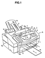
- FIG. 1 is a perspective view of the appearance of the facsimile machine according to this embodiment
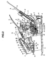
- Fig. 2 is a schematic cross-sectional view roughly showing a structure of the facsimile machine according to this embodiment.
- A represents a facsimile machine, and in a housing constituting side walls located on right, left, front, and rear sides, incorporated are a scanner unit 1 serving as an reading apparatus for reading images as feeding original documents, a printer unit 2 serving as a recording apparatus for performing serial recording as feeding recording sheets, a control panel, not shown, connected to those for controlling in a prescribed manner, and a power source 3.
- a scanner unit 1 serving as an reading apparatus for reading images as feeding original documents
- a printer unit 2 serving as a recording apparatus for performing serial recording as feeding recording sheets
- a control panel not shown, connected to those for controlling in a prescribed manner
- a power source 3 for controlling in a prescribed manner
- Those units are separately formed as to be replaceable and removal easily.
- the housing is basically formed of a lower cover 4 serving as a first housing on a lower side, an upper cover 5 serving as a second housing on an upper side, and a rear cover 6 serving as a third housing as described below for guiding the recording sheets and for covering the power source.
- An original document tray 7 for mountable of multiple number of original documents as sheets to be read is pivotably supported on the upper cover 5 and allows accesses to a recording head as described below.
- a slider 8 for adjusting width for guiding in respect to a width direction perpendicular to the conveyance direction is formed on the original document tray 7, and the slider 8 can make both sides move in the same way with respect to the middle portion of the slider as a center by moving only one side.
- a detachable original document tray 8 is formed on the original document tray 7, and when, for example, original documents of A size are fed toward the scanner unit 1, the tray 9 prevents the read end of the original documents from curving downward.
- the original documents fed to the scanner unit 1 are placed on an original document delivery tray 10 upon delivered in front of the facsimile machine A after images are read.
- the original delivery tray 10 is movable in the front and rear direction (arrow direction in Fig. 1).
- recording sheets as sheets of recording objects are set on a recording sheet tray 11 arranged at the rear of the facsimile machine A, and after positionally limited in the width direction by side guides 12 for adjusting width formed on the recording sheet tray 11, the recording sheets are fed sheet by sheet to the printer unit 2. After images are recorded at the printer unit 2 (serial recording), the recording sheets are delivered on the a recording sheet delivery tray 3 located below the scanner unit 1.
- the recording sheet tray 11 incorporates a recording sheet support 14 for preventing the recording sheets from curving down, and the recording sheet support 14 is constituted to take the position shown in Fig. 1 by pulling it properly.
- a recording sheet support bar 15 is formed to prevent the recording sheets from curing downward, and the recording sheets support bar 15 is movable in the front and rear direction (arrow direction in Fig. 1) in the same way as that of the original document delivery tray 10.
- the upper cover 5 has a shape to enclose the scanner unit 1 as shown in Fig. 1, and by removing the upper cover 5 from the lower cover 4 along an edge 5a of the upper cover 5, the scanner unit 1 can be remained on the lower cover 4.
- This scanner unit 1 is to radiate light on the original document G, to convert the reflected light to electrical signals, and to transmit the signals to other machines or the printer unit 2 within the apparatus depending on a control mode.
- numeral 21 is a scanner base as a frame for the scanner unit 1 and fixed to the lower cover 4.
- a lower original document guide 22 for guiding a lower side of the original documents G, a separation roller 23 for sending the original documents, a feeding roller 24 for feeding the original documents, a delivery roller 25 for delivering the original documents on the original document delivery tray 10, a color contact sensor 26 for reading image information of the original documents are formed on the scanner base 21.
- a panel portion 16 is connected to the scanner body 17 as to be open and closed with respect to the scanner body 17 around a hinge as a center.
- the panel portion 16 is formed with an upper original document guide 27 for guiding the upper side of the original documents, a separator 28 pushed by the separation roller 23, a feeding roller 29 pushed by the feeding roller 24, a delivery roller 30 pushed by the delivery roller 25, and white member for reading 31 pushed by the color contact sensor 26 serving as white reference for reading.
- Numeral 18 is a panel frame, a part of the housing, attached to the upper original document guide 27, formed with a display 16a such as LCD or the like, control keys 16b such as control dial keys, and a panel board 16c mounting those thereon.
- a display 16a such as LCD or the like
- control keys 16b such as control dial keys
- a panel board 16c mounting those thereon.
- the recording sheets S mounted on the recording sheet tray 11 (and the recording sheet support 14) are fed sheet by sheet by a feeding roller 32 while restricted on its position in the width direction by side guides 12 and sent to the printer unit 2.
- the printer unit 2 uses an ink jet recording method in which ink is sprayed from a recording head to record ink images on the recording sheets.
- numeral 41 is a printer chassis serving as a frame for printer unit 2, fixed to the lower cover 4.
- Numeral 42 is a transfer roller for feeding the recording sheets S sent from the sheet feeding section, by pressure of a pinch roller 43 arranged as to correspond to it, to the recording section located on the further downstream side.
- Numeral 44 is a platen supporting the back surface of the recording sheets at the recording section.
- recording images are formed by the recording head 47 attached to a carriage 46 reciprocally traveling supported on a guide shaft 45. Subsequently, the recording sheets S is delivered from the printer unit 2 by the delivery roller pair 48, and placed on the recording sheet delivery tray 13 formed on the lower cover 4.
- recording sheet conveyance, recording operation, and the like of the printer unit 2 can be done by a motor, sensors, a head drive circuit or the like, which are not shown, and the control board controls those members.
- a board 49 is a recording relay board for relaying signals for the motor, sensors, and head drive circuit and transmitting them to the control board.
- An absorber 50 for absorbing waste ink generated during preventive operation of ink clogging is attached to the lower cover 50.
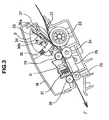
- Fig. 3 is an enlarged cross section of the scanner unit 1.
- the original documents G are set in an original document opening formed between the upper original document guide 27 and the lower original document guide 22, and are fed along a conveyance route shown by Arrow F.
- numeral 33 is a preliminary feeding arm located as to oppose to the separation roller 23.
- the preliminary feeding arm 33 is pushed to the separation roller 23 by a preliminary feeding spring 34. Therefore, the original documents G set on the tray 7 are handled by joint operation of the preliminary feeding arm 33 and the separation roller 23 and preliminarily fed.
- the separator 28 pushed to the separation roller 23 by an ADF (auto document feeder) spring 35 and of the separation roller 23 the preliminarily fed original documents G are fed separately sheet by sheet from their bottom.
- the separation roller 23 can serve for feeding the original documents G to the feeding roller 24.
- the original document G fed by the separation roller 23 is further fed to a reading position of the contact sensor 26 by the feeding rollers 24, 29, and the contact sensor 26 reads images.
- the original document G is in closely contact with a reading line of the contact sensor 26 by means of a reading white ground (white ground metal plate) 31 pushed by a white ground spring 37.
- the original document G, whose images are read by the contract sensor 26, is delivered on the original document delivery tray 10 by the delivery rollers 25, 30.
- FIG. 4 shows an enlarged view of the separation section.
- numeral 28 is the separator made of a frictional member such as a rubber piece and is attached onto an ADF holder 36.
- Numeral 33 is the preliminary feeding arm, which is made of a plastic member having a relatively small friction coefficient.
- a projection shaft 36a is formed on the ADF holder 36; a U-shaped portion 33a is formed on the preliminary feeding arm 33; the projection shaft 36a of the ADF holder 36 is attached to a recess of the U-shaped portion 33a.
- the preliminary feeding arm 33 is pivotally movable around the U-shaped portion 33a as a center.
- Numeral 34 is a preliminary feeding spring and coil spring. One end of the preliminary feeding spring 34, between both ends, is engaged with a projection of the preliminary feeding arm 33, and the other is engaged with a projection of the ADF holder 36.
- a U-shaped portion, not shown, is formed on the upper original document guide 27, and the projection shaft 36a of the ADF holder 36 is attached to a recess of the U-shaped portion.
- the ADF holder is pivotably movable around the projection shaft 36a as a center.
- the ADF holder 36 is located as to oppose to the separation roller 23 and is disposed so that the preliminary feeding arm 33 and the separator 28 are in contact with the separation roller 23.
- a receiving surface of the ADF holder 36 is engaged with one end of the ADF spring 35, and the other end of the spring 35 is engaged with the panel frame 18.
- the ADF spring 35 is a contracted coil spring, and since its elastic force is larger than elastic force of the preliminary feeding spring 34 on the ADF holder 36, the preliminary feeding arm 33 is pushed by the separation roller 23 by operation of the ADF spring 35 and the preliminary feeding spring 34.
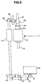
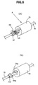
- Fig. 5 is a schematic view showing a layout of the separation roller 23, the feeding roller 24, a reading drive motor and gear series.
- Arrow F in the drawing is the conveyance direction of the original documents.
- Numeral 60 is a reading drive motor and is a stepping motor driven upon supply of a pulse current.
- a motor gear 61 is attached to a tip of the reading drive motor 60, and drive torque generated at the reading drive motor 60 is transmitted through the motor gear 61.
- Numerals 62, 63 are intermediate gears, gears for transmitting the drive torque from the reading drive motor 60 to the feeding roller 24, and two staged gears constituted of two gears having different tooth number from one another.
- Numerals 64, 65 are separation feeding gears, commonly having a D-shaped center hole. Both ends of the shaft of the feeding roller have a D-shape; the separation feeding gear 64 is attached to the D-shape portion of the end on the reading drive motor 60; the separation feeding gear 65 is attached to the D-shaped portion of the other end.
- the drive torque generated at the reading drive motor 60 is transmitted from the motor gear 61 to the separation feeding gear 64 through the intermediate 62, 63, thereby rotating the feeding roller 24.
- the gears 61 to 64 are a gear series for rotating the feeding roller 24.
- Numeral 66 is a separation intermediate gear; numeral 67 is a separation gear; and gears 65 to 67 are a gear series for rotating the separation roller 23.
- the separation feeding gear 65 rotates, by rotation of the feeding roller 24, in the same direction, and the drive torque is transmitted to the separation gear 67 through the separation intermediate gear 66.
- Numeral 68 is a spring clutch; numeral 69 is a clutch collar; and numeral 70 is a separation shaft.
- the separation roller 23, the separation gear 67, and the clutch collar 69 are freely rotated around the separation shaft 70 as a center.
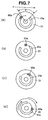
- FIG. 6(a) The constitution of the separation roller 23, the spring clutch 68, and the clutch collar 69 is described in reference to Fig. 6.
- Arrow F in the drawing is the conveyance direction of the original documents
- the other arrow is a rotary direction of the separation roller 23, the clutch collar 69, and the separation gear 67 while the original documents are fed.
- the spring clutch 68 transmits its drive torque to the clutch collar 69 when the separation gear 67 rotates in the conveyance direction of the original documents.
- the separation gear 67, the spring clutch 68, and the clutch collar 69 constitute a spring clutch mechanism in which the drive torque transmitted through the separation intermediate gear 66 from the separation feeding gear 65 is transmitted only when rotating in the conveyance direction of the original documents (normal direction).
- the clutch collar 69 is formed with a projection 69a, and the separation roller 23 is formed with a projection 23a.
- the torque is transmitted where the projection 69a of the clutch collar 69 rotates in the conveyance direction of the original documents and engages with the projection 23a of the separation roller 23, thereby rotating the separation roller 23 in the conveyance direction of the original documents.
- Fig. 6(b) is an exploded view as for relation between the projection 23a of the separation roller 23 and the projection 69a of the clutch collar 69.
- both are engaged with each other around the separation shaft 70 as a center so that the projection 69a of the clutch collar 69 meshes a cutout of the projection 23a of the separation roller 23.
- Both projections 23a, 69a are on the same rotary track around the separation shaft 70 as a center, and the projection 69a on the side of the clutch collar 69 is pivotally moved to contact with the projection 23a of the separation roller 23. Between both projections 23a, 69a, a play exists in the rotary track direction.
- the clutch collar 69 constitutes a first rotary member, whereas the end of the separation roller 23 constitutes a second rotary member, and the clutch collar 69 and the end of the separation roller 23 constitute a delaying means.
- the separation roller 23 is formed with the projection 23a
- the clutch collar 69 is formed with the projection 69a.
- the projection 69a of the clutch collar 69 is indicated with hatching in Fig. 7.
- Fig. 7(a) shows waiting positions of the projection 69a of the clutch collar 69 and the projection 23a of the separation roller 23 at a state that the reading drive motor 60 does not start yet rotating, namely, the initial state.
- P represents a space between the projection 69a of the clutch collar 69 and the projection 23a of the separation roller 23.
- the projection 69a of the clutch collar 69 engages with the projection 23a of the separation roller 23, and the separation roller 23 rotates in the conveyance direction of the original documents upon receiving the torque.
- the original documents starts to move in the conveyance direction at that time. That is, the separation roller 23 starts to rotate with a delay by a period from the start of the rotation of the feeding roller 24 for the projection 69a of the clutch collar 69 travels in the space P, thereby feeding the original documents.
- This delay timing is determined from the gear ratio of the gear series from the feeding roller 24 to the separation roller 23 and the size of the space (angle) P between the projection 69a of the clutch collar 69 and the projection 23a of the separation roller 23.
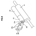
- FIG. 8 shows a perspective view of the stopper
- Fig. 9 shows a side cross section of the stopper.
- the drawings show a second feeding means constituted of the feeding roller 24 as a driving rotary body and the feeding roller 29, driven to rotate in pressurized contact with the roller 24, serving as a driven rotary body, a stopper roller 39, and a stopper 38 serving as a limiting means pivotable at a limiting position for limiting the front end of the original documents G set on the original document tray 7 and at an escape position for releasing the limitation.
- the stopper roller 39 has a rib 39 as a united body, which serves as a projection for switching the limitation and the release of the front end of the original documents by means of the stopper 38.
- the stopper 38 has, as a united body, a projection shaft 38a, a projection 38b as a projecting portion for engaging with the rib 39a of the stopper roller 39, and a stop surface 38c as a limiting portion for limiting the front end of the original documents.
- the stopper 38 is attached to a recess of a U-shaped member, not shown, on the upper original document guide 27 and can freely move pivotally around the projection shaft 38a as a center.
- the stopper 38 Operation of the stopper 38 is described in referring to Fig. 9.
- the rib 39a of the stopper roller 39 and the stop surface 38c of the stopper 38 wait at the limiting position (position shown in Fig. 9(a)) for limiting the front end of the original documents.
- the feeding roller 24 rotates in the conveyance direction (direction of Arrow)
- the feeding roller 29 and the stopper roller 39 are also driven to rotate in the conveyance direction (direction of Arrow) (see, Fig. 9(b)).
- the rib 39a of the stopper roller 39 also rotates as well, and the rib 39a hits the projection 38b of the stopper 38 (see, Fig. 9(c)).
- the rib 39a of the stopper roller 39 driven to rotate pushes down the projection 38b of the stopper 38.
- the stop surface 38c which has been limiting the front end of the original documents G around the projection shaft 38a of the stopper 38 as a center, is lifted up, thereby rendering the limitation on the front end gof the original documents G released (see, Fig. 9(d)).
- the stopper 38 is held at a state that the stop surface 38c is lifted (escaped to the escaping position) (see, Fig. 9(e)).
- the stop surface 38 is lowered by the weight of the stopper 38 and comes back to the limiting position (see, Fig. 9(f)).
- the stop surface 38c of the stopper 38 repeats to move up and down pivotally around the projection shaft 38a as a center.
- the timings that the separation roller 23 starts rotating and that the stopper 38 releases the front end of the original documents are determined by the gear series located between the feeding roller 24 and the feeding roller and the size of the space P between the projection 69a of the clutch collar 69 engages with the projection 23a of the separation roller 23.
- the space P is a mechanism to determine an interval between the original documents when multiple original documents are fed.
- the gear ratio (tooth number) of the gear series is determined at a designing state where the torque transmission from the feeding roller 24 and the original document interval are decided, and it is hard to change the ratio later in order to adjust the timing of the conveyance start.
- the timing that the stopper 38 releases the limitation on the front end g of the original documents is made earlier than the start of rotation of the separation roller 23 by adjusting the size (angle R) of the rib 39a of the stopper roller 39.
- R is the size (angle) of the rib 39a of the stopper roller 39, and the timing that the stopper 38 releases the limitation on the front end g of the original documents G can be adjusted easily by changing the angle R.
- the projection 38b of the stopper 38 and the rib 39a of the stopper roller 39 constitute a cam mechanism.
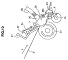
- FIG. 11 shows an initial state when original documents are set on the original document tray 7.
- G represents the set original documents; g represents the front end of the original documents; the hatching area is the rib 39a of the stopper roller 39.
- the front end g of the original documents G is set upon hitting the stop surface 38c of the stopper 38.
- a pulse current is supplied to the reading drive motor 60.
- Drive torque generated at the reading drive motor 60 is transmitted to the feeding roller 24 through the gear series, and the feeding roller 24 starts rotating in the conveyance direction of the original documents.
- the feeding roller 29 and the stopper roller 39 also rotate as following to the feeding roller 24, and the rib 39a of the stopper roller 39 also starts rotating in the same direction.
- the stop surface 38c moves up to the escape position around the projection shaft 38a as center, thereby releasing the front end of the original documents.
- the angle R of the rib 39a of the stopper roller 39 is designed to have a size such that the stop surface 38c of the stopper 38 move up to the escape position where the feeding roller 24 and the stopper roller 39 even slightly rotate. That is, before the separation roller 23 starts to rotate, the limitation on the front end of the original documents by the stop surface 38c of the stopper 38 is released. Accordingly, the apparatus can prevent conveyance failures such that the front end of the original documents is folded by striking the stop surface 38c of the stopper 38. Though the projection 69a of the clutch collar 69 engages, as further rotating, with the projection 23a of the separation roller 23, the separation roller 23 does not yet start rotating when the limitation on the front end g of the original documents is released (see, Fig. 11(b)).
- the projection 69a of the engaged clutch collar 69 transmits the torque to the separation roller 23, so that the separation roller 23 starts to rotate.
- the original documents G are sent to a contact area between the separator 28 and the separation roller 23 by the preliminary feeding arm 33 and the separation roller 23 which is in pressurized contact with the arm 33 and are separately fed sheet by sheet by means of the separator 28 and the separation roller 23 contacting with pressure.
- the stop surface 38c of the stopper 38 is held at a moved-up state (escape position) by the rib 39a of the stopper roller 39 and continuously releases the limitation on the front end g of the original documents (see, Fig. 11(c)).
- the angle R of the rib 39a of the stopper roller 39 is designed to have a size such that the stop surface 38c is held at the escape position until that the front end g of the original documents is fed on the downstream side of the stopper 38 in the conveyance direction after the limitation on the front end g of the original documents G set on the stop surface 38c in hitting thereon. Therefore, the apparatus can prevent conveyance failures such that the front end of the original documents is folded by striking the stop surface 38c of the stopper 38.
- the feeding roller 24 and the stopper roller 39 further rotate and when the rib 39a of the stopper roller 39 passes through the projection 38a of the stopper 38, the stop surface 38c of the stopper 38 moves down by its weight.
- the above description is for a case where the original documents G are set upon hitting the stop surface 38c of the stopper 38, the same operation would be made even where the original documents G are set in front of but not reaching the stop surface 38c of the stopper 38.
- the original documents are set in a state that the front end of the original documents (particularly, thin original documents) does not reach the stop surface 38c of the stopper 38 by an inadvertent user.
- the angle R of the rib 39a of the stopper roller 39 is small, the stop surface 38c of the stopper 38 moves down right after moving up.
- the front end of the original documents still does not reach the stop surface 38c of the stopper 38 (on the upstream side in the conveyance direction) even though the original documents start to be fed after the stop surface 38c of the stopper 38 moves up to the escape position, and therefore, a situation that after the stop surface 38c moves down the front end of the original documents reaches the stop surface 38c may occur, thereby creating risks of conveyance failures such that the front end of the original documents is folded.
- the angle R of the rib 39a of the stopper roller 39 is designed to have a size such that the stop surface 38c is held at the escape position until that at least the front end g of the original documents is fed on the downstream side of the stopper 38 in the conveyance direction. It is to be noted that as the angle R of the rib 39a of the stopper roller 39 is made larger, the time in which the stop surface 38c of the stopper 38 is held at the escape position is made longer.
- the stop surface 38c of the stopper 38 moves up to the escape position, and the stop surface 38c of the stopper 38 is held in a state that the stop surface 38c of the stopper 38 moves up at the escape position even after the original documents G start to be fed by rotation of the separation roller 23 but until the front end g of the original documents passes by the stopper 38 (see, Fig. 11(c)).
- the apparatus can prevent, with such a simple strucuture, conveyance failures such that the original documents are folded due to striking the stopper 38 by the front end g of the original documents.
- the separation roller 23 and the clutch collar 69 are operably connected with each other by projections having a play
- the same advantages can be obtained by setting that one end is made of a projection and the other end is made of a long groove, as a matter of course.
- the end of the long groove works as a projection, so that, in a broad sense, this is no different from power transmission done by projections.
- the feeding roller 29 and the stopper roller 39 are exemplified as separate parts, this invention is not limited to this, and those two parts can be a single united part. With such a structure, the same advantages as above can be obtained, and the apparatus can reduce the costs by reduction of the number of parts.
- a facsimile machine is exemplified as an image forming apparatus
- this invention is not limited to this and can be other image forming apparatuses such as photocopiers or the like, and substantially the same advantages can be obtained by application of the invention to a sheet feeding apparatus used for an image forming apparatus.
- the ink jet recording method is exemplified as a recording method.
- This invention is not limited to this, and for example, other recording methods such as electrophotographic methods can be used.
- this invention applies to the feeding system in which the original documents as sheets to be read are fed to a reading means.
- This invention is not limited to this, and the same advantages can be obtained by application of the invention to a feeding system in which recording sheets as sheets to be recorded are fed to a recording section.
- the apparatus has a structure that the limitation on the front end of the sheets by the limiting means is released before the sheets start to be fed, so that the apparatus can prevent conveyance failures such that the sheets are folded due to striking the limiting means by the front end of the sheets.
- the limiting means releasing the limitation on the front end of the sheets has a structure to be held in a state that the limitation is released, until at least the front end of the sheets is fed on the downstream side of the limiting means in the conveyance direction, so that even where the sheets (particularly, thin sheets) are set in not reaching the limiting means by an inadvertent user, the apparatus can prevent conveyance failures such that the sheets are folded due to striking the limiting means by the front end of the sheets.
- the apparatus is constituted of, as a feeding means for feeding sheets, a first feeding means for feeding separately sheet by sheet sheets inserted from an inlet, and a second feeding means placed in the downstream side of the first feeding means in the conveyance direction for starting rotation earlier than the first feeding means and is constituted that a limiting means moves to an escape position releasing the limitation on the front end of the sheets according to the rotation of the second feeding means, so that the apparatus can obtain the above advantages with a simple structure.
- the apparatus can realize switching of limitation and release of the front end of the sheets with such a simple structure.
- the limiting means is a pivotal member having a limiting portion on an upstream side of the pivotal movement shaft in the conveyance direction and a projection on a downstream side of the shaft in the conveyance direction; the limiting portion is moved pivotally to the escape position upon that the projection of the second feeding means pushes down the projection of the limiting means; the projection of the second feeding means pushes down the projection of the limiting means before the sheets start to be fed and keeps to push down the projection of the limiting means until at least the front end of the sheet is fed on the downstream side of the limiting means on the conveyance direction.
- the apparatus therefore can reduce the costs by reducing the number of parts and can prevent conveyance failures such that the sheets are folded due to striking the limiting means by the front end of the sheets.
Landscapes
- Engineering & Computer Science (AREA)
- Mechanical Engineering (AREA)
- Sheets, Magazines, And Separation Thereof (AREA)
- Handling Of Cut Paper (AREA)
- Facsimiles In General (AREA)
Claims (15)
- Bogenzuführvorrichtung, umfassend:dadurch gekennzeichnet, dasseine erste Zuführeinrichtung (23, 28) zum Zuführen von Bogen;eine in Förderrichtung (F) stromabwärts von der ersten Zuführeinrichtung (23, 28) angeordnete zweite Zuführeinrichtung (24, 29) zum Zuführen von von der ersten Zuführeinrichtung (23, 28) zugeführten Bogen;eine zu einer Begrenzungsposition zur Begrenzung eines vorderen Endes der Bogen und zu einer Freigabeposition entfernt von dem vorderen Ende der Bogen zur Aufhebung der Begrenzung bewegbare Begrenzungseinrichtung (38);eine Bewegungseinrichtung (39) zur Bewegung der Begrenzungseinrichtung (38) zur Freigabeposition, bevor die erste Zuführeinrichtung (23, 28) die Zuführung der Bogen beginnt,
die Begrenzungseinrichtung (38) ein vorderes Ende (g) des von einem Einlaß eingesetzten Bogenstapels begrenzt, und
dass die erste Zuführeinrichtung (23, 28) die Bogen getrennt, Bogen für Bogen, von dem Bogenstapel (G) zuführt. - Bogenzuführvorrichtung nach Anspruch 1, wobei die Begrenzungseinrichtung (38) in einem Zustand gehalten wird, in dem die Begrenzung aufgehoben ist, bis mindestens das vordere Ende (g) der getrennt zugeführten Bogen der stromabwärtigen Seite der Begrenzungseinrichtung (38) in Förderrichtung (F) zugeführt ist.
- Bogenzuführvorrichtung nach Anspruch 1 oder 2, wobei sich die Begrenzungseinrichtung (38) zur die Begrenzung aufhebenden Freigabeposition an dem vorderen Ende des Bogenstapels entsprechend der Drehung der zweiten Zuführeinrichtung (24, 29) bewegt.
- Bogenzuführvorrichtung nach Anspruch 3, wobei die Begrenzungseinrichtung (38) ein schwenkbar von der Begrenzungsposition bis zur Freigabeposition nach oben bewegbares Schwenkteil ist, das sich schwenkend nach oben zur Freigabeposition entsprechend der Drehung der zweiten Zuführeinrichtung (24, 29) und nach unten zur Begrenzungsposition durch das Gewicht der Begrenzungseinrichtung (38) bewegt.
- Bogenzuführvorrichtung nach Anspruch 4, wobei die Begrenzungseinrichtung (38) auf einer in Förderrichtung (F) stromaufwärtigen Seite einer Schwenkbewegungswelle (38a) einen Begrenzungsabschnitt (38c) und auf einer in Förderrichtung (F) stromabwärtigen Seite der Schwenkbewegungswelle (38a) einen Vorsprung (38b) aufweist, und der Begrenzungsabschnitt (38c) schwenkbar zur Freigabeposition bewegt wird, nachdem ein Vorsprung (39a) der zweiten Zuführeinrichtung (24, 29) den Vorsprung (38b) der Begrenzungseinrichtung (38) nach unten drückt.
- Bogenzuführvorrichtung nach Anspruch 5, wobei der Vorsprung (39a) der zweiten Zuführeinrichtung (24, 29) den Vorsprung (38b) der Begrenzungseinrichtung (38) herunterdrückt, bevor die Zuführung der Bogen (G) beginnt und den Vorsprung (38b) solange nach unten drückt, bis mindestens das vordere Ende der getrennt zugeführten Bogen der in Förderrichtung (F) stromabwärtigen Seite der Begrenzungseinrichtung (38) zugeführt ist.
- Bogenzuführvorrichtung nach einem der Ansprüche 3 bis 6, wobei die erste Zuführeinrichtung (23, 28) und die zweite Zuführeinrichtung (24, 29) nach Erhalt einer Antriebskraft von einer gemeinsamen Antriebseinrichtung (60) angetrieben werden, und eine Verzögerungseinrichtung (69, 23) zur Verzögerung des Antriebbeginns der ersten Zuführeinrichtung (23, 38) zwischen der Antriebseinrichtung (60) und der ersten Zuführeinrichtung (23, 28) angeordnet ist.
- Bogenzuführvorrichtung nach Anspruch 7, wobei die Verzögerungseinrichtung (69a, 23a) ein an einer Seite der Antriebseinrichtung (60) ausgebildetes erstes Drehteil (69) und ein an einer Seite der ersten Zuführeinrichtung (23, 28) ausgebildetes zweites Drehteil umfaßt, und Vorsprünge (23a, 69a) auf der gleichen Rotationsspur an gegenüberliegenden Seitenflächen des ersten und zweiten Drehteils ausgebildet sind und die Antriebskraft nach dem Eingriff der Vorsprünge (23a, 69a) übertragen wird, und die Vorsprünge zwischen sich ein Spiel (B) zur Verzögerung des Antriebs des zweiten Drehteils aufweisen.
- Bogenzuführvorrichtung nach Anspruch 1, wobei die erste Zuführeinrichtung (23, 28) eine Trennwalze (23) zum getrennten Zuführen der Bogen (G) umfaßt, wobei die Begrenzungseinrichtung (38) in Förderrichtung (F) der Bogen auf der stromabwärtigen Seite der Trennwalze (23) angeordnet ist, und wobei die Bogenzuführvorrichtung weiter eine Antriebseinrichtung (60) zum Antrieb der Trennwalze (23) und der Begrenzungseinrichtung (38) und einen zwischen der Begrenzungseinrichtung (38) und der Antriebseinrichtung (60) angeordneten Nockenmechanismus (38b, 39a) umfaßt, wobei die Begrenzung des vorderen Endes des Bogenstapels mittels des Nockenmechanismus (38b, 39a) aufgehoben wird.
- Bogenzuführvorrichtung nach Anspruch 9, wobei die zweite Zuführeinrichtung (24, 29) eine Zuführwalze (29) umfaßt, und wobei der Nockenmechanismus (38b, 39a) zwischen der Begrenzungseinrichtung (38) und der Zuführwalze (29) angeordnet ist.
- Bogenzuführvorrichtung nach Anspruch 9 oder 10, weiter umfassend eine zwischen der Trennwalze (23) und der Antriebseinrichtung (60) angeordnete Verzögerungseinrichtung (69, 23a), wobei die Verzögerungseinrichtung (69, 23a) ein an einer Seite der Antriebseinrichtung ausgebildetes erstes Drehteil (69) und ein an einer Seite der Trennwalze (23) ausgebildetes zweites Drehteil aufweist, und wobei Vorsprünge (23a, 69a) auf der gleichen Rotationsspur an gegenüberliegenden Seitenflächen des ersten und zweiten Drehteils ausgebildet sind, und eine Antriebskraft nach dem Eingriff der Vorsprünge (23a, 69a) übertragen wird, und die Vorsprünge zwischen sich ein Spiel (P) aufweisen, um den Anstriebsbeginn der Trennwalze (23) zu verzögern.
- Bogenzuführvorrichtung nach Anspruch 1, wobei die erste Zuführeinrichtung (23, 28) und die Bewegungseinrichtung (39) von einer gemeinsamen Antriebsquelle (60) angetrieben werden und die Vorrichtung weiter eine Verzögerungseinrichtung (69a, 23a) zur verzögerten Übertragung des Antriebsbeginns von der Antriebsquelle (60) zur ersten Zuführeinrichtung (23, 28) umfaßt, sodass der Antrieb der Antriebsquelle (60) zur ersten Zuführeinrichtung (23, 28) nach dem Bewegungsbeginn der Bewegungseinrichtung (39) zur Bewegung der Begrenzungseinrichtung (38) zur Freigabeposition übertragen wird.
- Bogenzuführvorrichtung nach Anspruch 12, wobei die Verzögerungseinrichtung (69, 23a) einen von der Antriebsquelle (60) gedrehten, ersten Drehkörper (69) und einen synchron mit der ersten Zuführeinrichtung (23, 28) drehbaren zweiten Drehkörper umfaßt, und weiter eine Eingriffseinrichtung (69a, 23a) zum Eingriff des ersten und zweiten Drehkörpers, nachdem sich der erste Drehkörper (69) um einen bestimmten Winkel gedreht hat, umfaßt.
- Bogenzuführvorrichtung nach Anspruch 1, 12 oder 13, wobei die erste Zuführeinrichtung (23, 28) eine Trennwalze zum Aufbringen einer Förderkraft durch Drehung auf einen Bogen des Bogenstapels umfasst, und ein Friktionsteil (28) so angeordnet ist, dass es der Trennwalze gegenüberliegt, wobei der von einem Einlaß eingesetzte Bogenstapel zwischen der Trennwalze (23) und dem Friktionsteil (28) angeordnet ist, und wobei die Trenneinrichtung eine Position des vorderen Endes des zwischen der Trennwalze (23) und dem Friktionsteil (28) angeordenete Bogenstapels begrenzt.
- Bilderzeugungsvorrichtung, umfassend eine Leseeinrichtung (26) zum Lesen von Abbildungen auf Bogen und eine Bogenzuführvorrichtung gemäß den Ansprüchen 1 bis 14 zur Zuführung von Bogen zu der Leseeinrichtung (26).
Applications Claiming Priority (3)
| Application Number | Priority Date | Filing Date | Title |
|---|---|---|---|
| JP25464097A JP3347652B2 (ja) | 1997-09-19 | 1997-09-19 | シート搬送装置及び画像形成装置 |
| JP254640/97 | 1997-09-19 | ||
| JP25464097 | 1997-09-19 |
Publications (3)
| Publication Number | Publication Date |
|---|---|
| EP0903310A2 EP0903310A2 (de) | 1999-03-24 |
| EP0903310A3 EP0903310A3 (de) | 1999-12-22 |
| EP0903310B1 true EP0903310B1 (de) | 2004-07-14 |
Family
ID=17267836
Family Applications (1)
| Application Number | Title | Priority Date | Filing Date |
|---|---|---|---|
| EP98117771A Expired - Lifetime EP0903310B1 (de) | 1997-09-19 | 1998-09-18 | Bogenzuführvorrichtung und Bilderzeugungsvorrichtung |
Country Status (4)
| Country | Link |
|---|---|
| US (1) | US6392763B1 (de) |
| EP (1) | EP0903310B1 (de) |
| JP (1) | JP3347652B2 (de) |
| DE (1) | DE69824999T2 (de) |
Families Citing this family (19)
| Publication number | Priority date | Publication date | Assignee | Title |
|---|---|---|---|---|
| JP3440067B2 (ja) * | 2000-09-29 | 2003-08-25 | パナソニック コミュニケーションズ株式会社 | 給紙装置及び通信装置 |
| US7149005B2 (en) * | 2002-08-06 | 2006-12-12 | Teco Image Systems Co., Ltd. | Depth of field control device |
| US6893013B2 (en) * | 2002-12-27 | 2005-05-17 | Lexmark International, Inc. | Input tray mechanical blocking apparatus |
| US7210677B2 (en) | 2003-07-04 | 2007-05-01 | Murata Kikai Kabushiki Kaisha | Paper feeder and image scanning device |
| JP4323973B2 (ja) * | 2004-02-04 | 2009-09-02 | キヤノン株式会社 | シート給送装置及びこれを備えた画像形成装置並びに画像読取装置 |
| JP4059218B2 (ja) * | 2004-03-15 | 2008-03-12 | ブラザー工業株式会社 | 給紙装置 |
| JP4541872B2 (ja) * | 2004-12-22 | 2010-09-08 | 日立オムロンターミナルソリューションズ株式会社 | 通帳繰出し機構 |
| JP2007290794A (ja) | 2006-04-21 | 2007-11-08 | Noritsu Koki Co Ltd | シート搬送装置 |
| US7651083B2 (en) | 2006-09-21 | 2010-01-26 | Digital Check Corporation | Conveying apparatus and method |
| US7753363B2 (en) * | 2007-05-09 | 2010-07-13 | Foxlink Image Technology Co., Ltd. | Paper feeding device |
| JP5538920B2 (ja) * | 2009-02-12 | 2014-07-02 | キヤノン株式会社 | シート綴じ装置及び画像形成装置 |
| TWI352666B (en) * | 2009-07-24 | 2011-11-21 | Kinpo Elect Inc | Paper feeding module and scanning device |
| US8215633B2 (en) | 2010-08-30 | 2012-07-10 | Eastman Kodak Company | Media stopper method for a printing system |
| US8215631B2 (en) | 2010-08-30 | 2012-07-10 | Eastman Kodak Company | Pick roller retraction in a carriage printer |
| US8215632B2 (en) | 2010-08-30 | 2012-07-10 | Eastman Kodak Company | Pick roller retraction method in a carriage printer |
| US8328183B2 (en) | 2010-08-30 | 2012-12-11 | Eastman Kodak Company | Media stopper for a printing system |
| JP5706132B2 (ja) * | 2010-11-10 | 2015-04-22 | キヤノン電子株式会社 | 原稿読取装置及びその制御方法 |
| US9181050B2 (en) * | 2010-11-10 | 2015-11-10 | Canon Denshi Kabushiki Kaisha | Sheet feeding apparatus, control method thereof, and document reading apparatus |
| JP6372408B2 (ja) | 2015-03-31 | 2018-08-15 | ブラザー工業株式会社 | 給紙装置 |
Family Cites Families (9)
| Publication number | Priority date | Publication date | Assignee | Title |
|---|---|---|---|---|
| GB2065610B (en) | 1979-11-27 | 1984-04-04 | Konishiroku Photo Ind | Sheet feeding apparatus |
| JPS58172136A (ja) * | 1982-03-30 | 1983-10-08 | Toshiba Corp | 紙葉類の分離給送装置 |
| JPS6160547A (ja) | 1984-08-30 | 1986-03-28 | Mita Ind Co Ltd | シ−ト送り装置のシ−トストツパ |
| US4606536A (en) | 1985-04-12 | 1986-08-19 | Ricoh Electronics, Inc. | Stopper plate apparatus for automatic document feeder |
| JPH0611628B2 (ja) | 1986-03-11 | 1994-02-16 | コニカ株式会社 | 手差し給紙機能を有する複写装置 |
| US5228671A (en) | 1992-11-20 | 1993-07-20 | Xerox Corporation | Sheet feeder with single sheet bypass |
| JP3190247B2 (ja) * | 1996-03-13 | 2001-07-23 | キヤノン株式会社 | シート材給送装置及び画像形成装置 |
| US5984298A (en) * | 1996-11-15 | 1999-11-16 | Mita Industrial Co., Ltd. | Sheet feeding apparatus with a driving device for a paper stopper |
| JPH11174757A (ja) * | 1997-12-11 | 1999-07-02 | Fuji Xerox Co Ltd | 画像形成装置 |
-
1997
- 1997-09-19 JP JP25464097A patent/JP3347652B2/ja not_active Expired - Fee Related
-
1998
- 1998-09-16 US US09/154,517 patent/US6392763B1/en not_active Expired - Lifetime
- 1998-09-18 EP EP98117771A patent/EP0903310B1/de not_active Expired - Lifetime
- 1998-09-18 DE DE69824999T patent/DE69824999T2/de not_active Expired - Lifetime
Also Published As
| Publication number | Publication date |
|---|---|
| JP3347652B2 (ja) | 2002-11-20 |
| EP0903310A2 (de) | 1999-03-24 |
| EP0903310A3 (de) | 1999-12-22 |
| US6392763B1 (en) | 2002-05-21 |
| DE69824999D1 (de) | 2004-08-19 |
| DE69824999T2 (de) | 2005-07-21 |
| JPH1191972A (ja) | 1999-04-06 |
Similar Documents
| Publication | Publication Date | Title |
|---|---|---|
| EP0903310B1 (de) | Bogenzuführvorrichtung und Bilderzeugungsvorrichtung | |
| US8333523B2 (en) | Recording device with link mechanism configured to link path changing unit to feed roller arm | |
| US7536129B2 (en) | Power transmitting apparatus, power switching apparatus, and driving apparatus of multi-function machine using the same | |
| EP1256534A2 (de) | Vorrichtung zum Zuführen von bogenförmigem Material und Aufzeichnungsgerät | |
| JP3296978B2 (ja) | 画像入力装置における駆動切換装置 | |
| EP1769932B1 (de) | Bildaufzeichnungsgerät mit Blattvorschubeinrichtung | |
| EP1609748B1 (de) | Zuführvorrichtung für Blätter | |
| US8072653B2 (en) | Image reading and recording apparatus | |
| EP0516118B1 (de) | Vorrichtung zum Papiertransport für Aufzeichnungsgerät | |
| JP2003005473A (ja) | 原稿送り装置及び画像形成装置 | |
| US5308175A (en) | Printer with reverse sheet feed path to sheet inlet | |
| JP2004051302A (ja) | 給紙装置及びこの給紙装置を搭載した印字装置 | |
| JP2803577B2 (ja) | 給紙装置 | |
| US6347213B1 (en) | Automatic original document conveying apparatus and image forming apparatus | |
| US5529407A (en) | Image recording apparatus | |
| CN113225445A (zh) | 图像读取装置和图像形成装置 | |
| US6416050B1 (en) | Auto sheet feeder | |
| JP2643218B2 (ja) | 積層枚葉紙位置決め装置 | |
| JPH1051598A (ja) | 原稿読取装置 | |
| EP1215536B1 (de) | Automatisches Dokumentzuführgerät und Bilderzeugungsvorrichtung mit einem solchen Gerät | |
| JPH09249321A (ja) | シート給送装置及び画像形成装置 | |
| JP3825895B2 (ja) | シート分離搬送装置及びこれを備える画像形成装置 | |
| KR100421030B1 (ko) | 잉크젯 팩시밀리의 용지이송장치 | |
| KR940001966B1 (ko) | 팩시밀리 구동장치 | |
| JP3646075B2 (ja) | 原稿供給装置 |
Legal Events
| Date | Code | Title | Description |
|---|---|---|---|
| PUAI | Public reference made under article 153(3) epc to a published international application that has entered the european phase |
Free format text: ORIGINAL CODE: 0009012 |
|
| AK | Designated contracting states |
Kind code of ref document: A2 Designated state(s): DE ES FR GB IT |
|
| AX | Request for extension of the european patent |
Free format text: AL;LT;LV;MK;RO;SI |
|
| PUAL | Search report despatched |
Free format text: ORIGINAL CODE: 0009013 |
|
| AK | Designated contracting states |
Kind code of ref document: A3 Designated state(s): AT BE CH CY DE DK ES FI FR GB GR IE IT LI LU MC NL PT SE |
|
| AX | Request for extension of the european patent |
Free format text: AL;LT;LV;MK;RO;SI |
|
| 17P | Request for examination filed |
Effective date: 20000508 |
|
| AKX | Designation fees paid |
Free format text: DE ES FR GB IT |
|
| 17Q | First examination report despatched |
Effective date: 20020328 |
|
| GRAP | Despatch of communication of intention to grant a patent |
Free format text: ORIGINAL CODE: EPIDOSNIGR1 |
|
| GRAS | Grant fee paid |
Free format text: ORIGINAL CODE: EPIDOSNIGR3 |
|
| GRAA | (expected) grant |
Free format text: ORIGINAL CODE: 0009210 |
|
| AK | Designated contracting states |
Kind code of ref document: B1 Designated state(s): DE ES FR GB IT |
|
| PG25 | Lapsed in a contracting state [announced via postgrant information from national office to epo] |
Ref country code: IT Free format text: LAPSE BECAUSE OF FAILURE TO SUBMIT A TRANSLATION OF THE DESCRIPTION OR TO PAY THE FEE WITHIN THE PRESCRIBED TIME-LIMIT;WARNING: LAPSES OF ITALIAN PATENTS WITH EFFECTIVE DATE BEFORE 2007 MAY HAVE OCCURRED AT ANY TIME BEFORE 2007. THE CORRECT EFFECTIVE DATE MAY BE DIFFERENT FROM THE ONE RECORDED. Effective date: 20040714 |
|
| REG | Reference to a national code |
Ref country code: GB Ref legal event code: FG4D |
|
| REF | Corresponds to: |
Ref document number: 69824999 Country of ref document: DE Date of ref document: 20040819 Kind code of ref document: P |
|
| PG25 | Lapsed in a contracting state [announced via postgrant information from national office to epo] |
Ref country code: ES Free format text: LAPSE BECAUSE OF FAILURE TO SUBMIT A TRANSLATION OF THE DESCRIPTION OR TO PAY THE FEE WITHIN THE PRESCRIBED TIME-LIMIT Effective date: 20041025 |
|
| ET | Fr: translation filed | ||
| PLBE | No opposition filed within time limit |
Free format text: ORIGINAL CODE: 0009261 |
|
| STAA | Information on the status of an ep patent application or granted ep patent |
Free format text: STATUS: NO OPPOSITION FILED WITHIN TIME LIMIT |
|
| 26N | No opposition filed |
Effective date: 20050415 |
|
| PGFP | Annual fee paid to national office [announced via postgrant information from national office to epo] |
Ref country code: FR Payment date: 20121009 Year of fee payment: 15 |
|
| REG | Reference to a national code |
Ref country code: FR Ref legal event code: ST Effective date: 20140530 |
|
| PG25 | Lapsed in a contracting state [announced via postgrant information from national office to epo] |
Ref country code: FR Free format text: LAPSE BECAUSE OF NON-PAYMENT OF DUE FEES Effective date: 20130930 |
|
| PGFP | Annual fee paid to national office [announced via postgrant information from national office to epo] |
Ref country code: GB Payment date: 20150922 Year of fee payment: 18 Ref country code: DE Payment date: 20150930 Year of fee payment: 18 |
|
| REG | Reference to a national code |
Ref country code: DE Ref legal event code: R119 Ref document number: 69824999 Country of ref document: DE |
|
| GBPC | Gb: european patent ceased through non-payment of renewal fee |
Effective date: 20160918 |
|
| PG25 | Lapsed in a contracting state [announced via postgrant information from national office to epo] |
Ref country code: DE Free format text: LAPSE BECAUSE OF NON-PAYMENT OF DUE FEES Effective date: 20170401 Ref country code: GB Free format text: LAPSE BECAUSE OF NON-PAYMENT OF DUE FEES Effective date: 20160918 |