EP0902994B1 - Connecteur de batterie rechargeable - Google Patents
Connecteur de batterie rechargeable Download PDFInfo
- Publication number
- EP0902994B1 EP0902994B1 EP97920906A EP97920906A EP0902994B1 EP 0902994 B1 EP0902994 B1 EP 0902994B1 EP 97920906 A EP97920906 A EP 97920906A EP 97920906 A EP97920906 A EP 97920906A EP 0902994 B1 EP0902994 B1 EP 0902994B1
- Authority
- EP
- European Patent Office
- Prior art keywords
- housing
- connector
- terminal
- contact
- spring
- Prior art date
- Legal status (The legal status is an assumption and is not a legal conclusion. Google has not performed a legal analysis and makes no representation as to the accuracy of the status listed.)
- Expired - Lifetime
Links
- 230000001681 protective effect Effects 0.000 claims abstract description 5
- 230000013011 mating Effects 0.000 claims description 27
- 230000000295 complement effect Effects 0.000 claims description 17
- 230000014759 maintenance of location Effects 0.000 claims description 10
- 238000003780 insertion Methods 0.000 claims description 3
- 230000037431 insertion Effects 0.000 claims description 3
- 230000008878 coupling Effects 0.000 description 3
- 238000010168 coupling process Methods 0.000 description 3
- 238000005859 coupling reaction Methods 0.000 description 3
- 239000002184 metal Substances 0.000 description 3
- 238000005192 partition Methods 0.000 description 3
- 229910000679 solder Inorganic materials 0.000 description 2
- FPWNLURCHDRMHC-UHFFFAOYSA-N 4-chlorobiphenyl Chemical compound C1=CC(Cl)=CC=C1C1=CC=CC=C1 FPWNLURCHDRMHC-UHFFFAOYSA-N 0.000 description 1
- 230000001413 cellular effect Effects 0.000 description 1
- 238000004140 cleaning Methods 0.000 description 1
- 230000006835 compression Effects 0.000 description 1
- 238000007906 compression Methods 0.000 description 1
- 238000010276 construction Methods 0.000 description 1
- 230000000994 depressogenic effect Effects 0.000 description 1
- 238000004519 manufacturing process Methods 0.000 description 1
- 238000000034 method Methods 0.000 description 1
- 238000003825 pressing Methods 0.000 description 1
Images


Classifications
-
- H—ELECTRICITY
- H01—ELECTRIC ELEMENTS
- H01R—ELECTRICALLY-CONDUCTIVE CONNECTIONS; STRUCTURAL ASSOCIATIONS OF A PLURALITY OF MUTUALLY-INSULATED ELECTRICAL CONNECTING ELEMENTS; COUPLING DEVICES; CURRENT COLLECTORS
- H01R13/00—Details of coupling devices of the kinds covered by groups H01R12/70 or H01R24/00 - H01R33/00
- H01R13/02—Contact members
- H01R13/22—Contacts for co-operating by abutting
- H01R13/24—Contacts for co-operating by abutting resilient; resiliently-mounted
- H01R13/2407—Contacts for co-operating by abutting resilient; resiliently-mounted characterized by the resilient means
- H01R13/2428—Contacts for co-operating by abutting resilient; resiliently-mounted characterized by the resilient means using meander springs
-
- H—ELECTRICITY
- H01—ELECTRIC ELEMENTS
- H01M—PROCESSES OR MEANS, e.g. BATTERIES, FOR THE DIRECT CONVERSION OF CHEMICAL ENERGY INTO ELECTRICAL ENERGY
- H01M50/00—Constructional details or processes of manufacture of the non-active parts of electrochemical cells other than fuel cells, e.g. hybrid cells
- H01M50/50—Current conducting connections for cells or batteries
-
- H—ELECTRICITY
- H01—ELECTRIC ELEMENTS
- H01R—ELECTRICALLY-CONDUCTIVE CONNECTIONS; STRUCTURAL ASSOCIATIONS OF A PLURALITY OF MUTUALLY-INSULATED ELECTRICAL CONNECTING ELEMENTS; COUPLING DEVICES; CURRENT COLLECTORS
- H01R12/00—Structural associations of a plurality of mutually-insulated electrical connecting elements, specially adapted for printed circuits, e.g. printed circuit boards [PCB], flat or ribbon cables, or like generally planar structures, e.g. terminal strips, terminal blocks; Coupling devices specially adapted for printed circuits, flat or ribbon cables, or like generally planar structures; Terminals specially adapted for contact with, or insertion into, printed circuits, flat or ribbon cables, or like generally planar structures
- H01R12/70—Coupling devices
- H01R12/71—Coupling devices for rigid printing circuits or like structures
- H01R12/712—Coupling devices for rigid printing circuits or like structures co-operating with the surface of the printed circuit or with a coupling device exclusively provided on the surface of the printed circuit
- H01R12/714—Coupling devices for rigid printing circuits or like structures co-operating with the surface of the printed circuit or with a coupling device exclusively provided on the surface of the printed circuit with contacts abutting directly the printed circuit; Button contacts therefore provided on the printed circuit
-
- H—ELECTRICITY
- H01—ELECTRIC ELEMENTS
- H01R—ELECTRICALLY-CONDUCTIVE CONNECTIONS; STRUCTURAL ASSOCIATIONS OF A PLURALITY OF MUTUALLY-INSULATED ELECTRICAL CONNECTING ELEMENTS; COUPLING DEVICES; CURRENT COLLECTORS
- H01R13/00—Details of coupling devices of the kinds covered by groups H01R12/70 or H01R24/00 - H01R33/00
- H01R13/02—Contact members
- H01R13/22—Contacts for co-operating by abutting
- H01R13/24—Contacts for co-operating by abutting resilient; resiliently-mounted
- H01R13/2442—Contacts for co-operating by abutting resilient; resiliently-mounted with a single cantilevered beam
-
- H—ELECTRICITY
- H01—ELECTRIC ELEMENTS
- H01R—ELECTRICALLY-CONDUCTIVE CONNECTIONS; STRUCTURAL ASSOCIATIONS OF A PLURALITY OF MUTUALLY-INSULATED ELECTRICAL CONNECTING ELEMENTS; COUPLING DEVICES; CURRENT COLLECTORS
- H01R12/00—Structural associations of a plurality of mutually-insulated electrical connecting elements, specially adapted for printed circuits, e.g. printed circuit boards [PCB], flat or ribbon cables, or like generally planar structures, e.g. terminal strips, terminal blocks; Coupling devices specially adapted for printed circuits, flat or ribbon cables, or like generally planar structures; Terminals specially adapted for contact with, or insertion into, printed circuits, flat or ribbon cables, or like generally planar structures
- H01R12/50—Fixed connections
- H01R12/51—Fixed connections for rigid printed circuits or like structures
- H01R12/55—Fixed connections for rigid printed circuits or like structures characterised by the terminals
- H01R12/57—Fixed connections for rigid printed circuits or like structures characterised by the terminals surface mounting terminals
-
- H—ELECTRICITY
- H01—ELECTRIC ELEMENTS
- H01R—ELECTRICALLY-CONDUCTIVE CONNECTIONS; STRUCTURAL ASSOCIATIONS OF A PLURALITY OF MUTUALLY-INSULATED ELECTRICAL CONNECTING ELEMENTS; COUPLING DEVICES; CURRENT COLLECTORS
- H01R12/00—Structural associations of a plurality of mutually-insulated electrical connecting elements, specially adapted for printed circuits, e.g. printed circuit boards [PCB], flat or ribbon cables, or like generally planar structures, e.g. terminal strips, terminal blocks; Coupling devices specially adapted for printed circuits, flat or ribbon cables, or like generally planar structures; Terminals specially adapted for contact with, or insertion into, printed circuits, flat or ribbon cables, or like generally planar structures
- H01R12/70—Coupling devices
- H01R12/71—Coupling devices for rigid printing circuits or like structures
- H01R12/712—Coupling devices for rigid printing circuits or like structures co-operating with the surface of the printed circuit or with a coupling device exclusively provided on the surface of the printed circuit
- H01R12/716—Coupling device provided on the PCB
-
- Y—GENERAL TAGGING OF NEW TECHNOLOGICAL DEVELOPMENTS; GENERAL TAGGING OF CROSS-SECTIONAL TECHNOLOGIES SPANNING OVER SEVERAL SECTIONS OF THE IPC; TECHNICAL SUBJECTS COVERED BY FORMER USPC CROSS-REFERENCE ART COLLECTIONS [XRACs] AND DIGESTS
- Y02—TECHNOLOGIES OR APPLICATIONS FOR MITIGATION OR ADAPTATION AGAINST CLIMATE CHANGE
- Y02E—REDUCTION OF GREENHOUSE GAS [GHG] EMISSIONS, RELATED TO ENERGY GENERATION, TRANSMISSION OR DISTRIBUTION
- Y02E60/00—Enabling technologies; Technologies with a potential or indirect contribution to GHG emissions mitigation
- Y02E60/10—Energy storage using batteries
Definitions
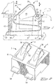
- This invention relates to an electrical connector mountable on a printed circuit board and having spring contacts for resiliently contacting a device, in particular a removable rechargeable battery.
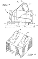
- an electrical connector comprising a housing having a cavity extending therethrough from a mounting face to a mating face, and a terminal mounted in the cavity, the terminal having a connection portion, a contact portion for contacting a complementary contact, and a supple spring portion extending between the contact and connection portions, the terminal contact portion protruding beyond the mating face, wherein the contact portion is resiliently pivotly attached to the spring portion at one end, and attached to a free end portion at an opposed end, the opposed ends positioned proximate opposed end walls in the housing cavity, wherein upon biasing of the contact in the housing, the free end portion is resiliently biasable against the corresponding cavity end wall for positioning the contact portion in a direction transverse to the direction of spring biasing of the terminal.
- an electrical connector 2 for connection to a device 1 comprises a pair of terminals 4 mounted in an insulative housing 6.
- the connector 2 is mounted in a device such as a cellular phone, having a casing 15 and a printed circuit board 3.
- the housing 6 extends from a mounting face 8 to a mating face 10, and has terminal receiving cavities 12 extending in a mating direction D for receiving the terminals 4 therein.
- the connector 2 is mountable on the printed circuit board (not shown) where the mounting face 8 is adjacent the printed circuit board, and the mating face 10 facing a complementary connector 3 for mating with the connector 2.
- the complementary connector may be planar contact pads 7 of a rechargeable replaceable battery or other power supply that forms the device 1.
- the free end portion 22 is further provided with a convex abutment surface 48 that abuts an end-wall 50 of the cavity 12 when the contact portion 20 is depressed into the housing.
- the U-bend 24 of the spring portion 18 abuts the opposed end-wall 52 of the cavity 12 such that the contact is guided in a direction transverse to the direction D during depression thereof.
- the contact point 38 moves in a pivoting motion about the U-bend 24, thereby enabling some transverse movement of the contact during coupling.
- the latter provides a wiping action that advantageously removes dirt or oxides on the contact surfaces, which is particularly useful for mating in the direction D.
Landscapes
- Chemical & Material Sciences (AREA)
- Chemical Kinetics & Catalysis (AREA)
- Electrochemistry (AREA)
- General Chemical & Material Sciences (AREA)
- Coupling Device And Connection With Printed Circuit (AREA)
Abstract
Claims (13)
- Connecteur électrique (2, 2') comprenant un boítier (6) comportant une cavité (12) le traversant, d'une face de montage (8) vers une face d'accouplement (10) et une borne (4, 4') montée dans la cavité (12), la borne comportant une partie de connexion (14), une partie de contact (20) destinée à contacter un contact complémentaire, et une partie élastique souple (18) s'étendant entre les parties de contact et de connexion, la partie de contact de la borne débordant au-delà de la face d'accouplement (10), caractérisé en ce que la partie de contact (20) est fixée élastiquement et par pivotement à la partie élastique au niveau d'une extrémité (24) et fixée à une partie d'extrémité libre (22) au niveau d'une extrémité opposée, les extrémités opposées étant positionnées près des parois d'extrémité opposées (50, 52) dans la cavité du boítier (12), la poussée de la partie de contact (20) dans le boítier permettant de pousser élastiquement la partie d'extrémité libre contre la paroi d'extrémité correspondante de la cavité (50) pour positionner la partie de contact dans une direction transversale à la direction (D) de la poussée élastique de la borne.
- Connecteur selon la revendication 1, dans lequel l'extrémité (24) de la partie élastique à laquelle est fixée élastiquement et par pivotement la partie de contact, bute contre la paroi d'extrémité correspondante (52) de la cavité du boítier au cours de la poussée de la partie de contact dans la cavité du boítier (12).
- Connecteur selon les revendications 1 ou 2, dans lequel la partie de connexion de la borne (14, 14') comprend des plots ou des branches à montage en surface sur la plaquette à circuits imprimés (56, 56', 57') positionnés au-dessous du boítier (6) et fixés à la section élastique (18), la partie de connexion étant presque entièrement positionnée au-dessous du boítier en vue d'occuper une aire de surface minimale de la plaquette à circuits imprimés.
- Connecteur selon l'une quelconque des revendications 1 à 3, dans lequel la partie de connexion de la borne (14) comprend des plots à montage en surface sur la plaquette à circuits imprimés (56) positionnés au-dessous du boítier (6) par fixation à la section élastique (18) par l'intermédiaire d'une courbure en U (54).
- Connecteur selon l'une quelconque des revendications 1 à 3, dans lequel la partie de connexion de la borne (14') comprend une base s'étendant à partir d'un bras (30') de la partie élastique (18), des branches de la plaquette à circuits imprimés (56', 57') s'étendant de manière pratiquement orthogonale à partir des bords latéraux (59, 61) de la base en vue d'une connexion à montage en surface sur une plaquette à circuits imprimés (3).
- Connecteur selon la revendication 5, dans lequel une paire de branches de la plaquette à circuits imprimés (56', 57') sont séparées par un évidement (55') agencé dans la direction de l'extension du bras élastique (30') sur chaque bord (59, 61).
- Connecteur selon l'une quelconque des revendications 1 à 6, dans lequel au moins une plaque de protection (46) est agencée au-dessous de la partie de contact pour empêcher l'insertion d'objets externes entre la partie de contact en saillie et la partie d'accouplement du connecteur.
- Connecteur selon la revendication 7, dans lequel la plaque de protection (46) est formée d'une seule pièce et courbée à partir de la partie de contact (20).
- Connecteur selon l'une quelconque des revendications précédentes, dans lequel une partie d'extrémité libre (22) au niveau d'une extrémité libre de la partie de contact (20) comporte un élément à précontrainte (40) s'engageant dans un élément à précontrainte complémentaire (44) du boítier pour soumettre la borne à une précontrainte dans l'état non accouplé.
- Connecteur selon la revendication 9, dans lequel l'élément de précontrainte du contact (40) est une extension latérale en forme d'aile (40) butant contre un épaulement du boítier (44) constituant l'élément à précontrainte complémentaire.
- Connecteur selon l'une quelconque des revendications précédentes, dans lequel la borne est assemblée dans la cavité du boítier (12) à partir de la face de montage dans la direction (D) de la poussée élastique de la borne.
- Connecteur selon la revendication 11, dans lequel la borne comprend une patte de retenue (34) s'étendant dans la direction de la poussée élastique de la borne (D) et agencée au niveau d'une extrémité de la partie élastique (18) près de la partie de connexion, en vue de l'insertion dans une cavité (36) du boítier par ajustement serré.
- Connecteur selon la revendication 11, dans lequel le boítier comporte des éléments de verrou (36', 37') s'engageant dans la partie de montage de la borne (14') au cours de l'assemblage pour y fixer la borne.
Priority Applications (1)
| Application Number | Priority Date | Filing Date | Title |
|---|---|---|---|
| EP97920906A EP0902994B1 (fr) | 1996-05-31 | 1997-05-27 | Connecteur de batterie rechargeable |
Applications Claiming Priority (6)
| Application Number | Priority Date | Filing Date | Title |
|---|---|---|---|
| GB9611337 | 1996-05-31 | ||
| GBGB9611337.8A GB9611337D0 (en) | 1996-05-31 | 1996-05-31 | Rechargable battery connector |
| EP96119704 | 1996-12-09 | ||
| EP96119704 | 1996-12-09 | ||
| EP97920906A EP0902994B1 (fr) | 1996-05-31 | 1997-05-27 | Connecteur de batterie rechargeable |
| PCT/IB1997/000593 WO1997045900A1 (fr) | 1996-05-31 | 1997-05-27 | Connecteur de batterie rechargeable |
Publications (2)
| Publication Number | Publication Date |
|---|---|
| EP0902994A1 EP0902994A1 (fr) | 1999-03-24 |
| EP0902994B1 true EP0902994B1 (fr) | 2001-11-28 |
Family
ID=26142353
Family Applications (1)
| Application Number | Title | Priority Date | Filing Date |
|---|---|---|---|
| EP97920906A Expired - Lifetime EP0902994B1 (fr) | 1996-05-31 | 1997-05-27 | Connecteur de batterie rechargeable |
Country Status (5)
| Country | Link |
|---|---|
| EP (1) | EP0902994B1 (fr) |
| JP (1) | JP3923532B2 (fr) |
| AU (1) | AU2710897A (fr) |
| DE (1) | DE69708625T2 (fr) |
| WO (1) | WO1997045900A1 (fr) |
Cited By (5)
| Publication number | Priority date | Publication date | Assignee | Title |
|---|---|---|---|---|
| DE10318524B4 (de) * | 2002-05-08 | 2006-06-08 | Tyco Electronics Nederland B.V. | Elektrischer Verbinder mit einer Anschlagfläche für eine Kontaktfeder |
| DE102011080645A1 (de) | 2011-08-09 | 2013-02-14 | Tyco Electronics Amp Gmbh | Elektrische kontaktfeder, elektrische federkontakteinrichtung sowie elektrische kontaktzone |
| TWI456821B (zh) * | 2009-05-22 | 2014-10-11 | Chi Mei Comm Systems Inc | 電池連接器、電池容置結構及電池 |
| US9203172B2 (en) | 2013-02-05 | 2015-12-01 | Tyco Electronics Japan G.K. | Electrical connector assembly and electrical connector used therefor |
| US11271338B2 (en) | 2019-04-25 | 2022-03-08 | Tyco Electronics Japan G.K. | Electrical connection assembly and electrical apparatus |
Families Citing this family (35)
| Publication number | Priority date | Publication date | Assignee | Title |
|---|---|---|---|---|
| EP0924804B1 (fr) * | 1997-12-22 | 2003-03-12 | The Whitaker Corporation | Connecteur électrique avec des lames élastiques |
| JPH11250966A (ja) * | 1997-12-22 | 1999-09-17 | Whitaker Corp:The | コネクタ |
| GB9804333D0 (en) * | 1998-02-27 | 1998-04-22 | Amp Great Britain | Device-to-board electrical connector |
| US5980335A (en) * | 1998-03-27 | 1999-11-09 | Molex Incorporated | Electrical terminal |
| FR2788780B1 (fr) * | 1999-01-27 | 2001-03-30 | Ap Cells Inc | Procede de preparation de vesicules membranaires |
| JP3286783B2 (ja) * | 1999-02-18 | 2002-05-27 | 日本航空電子工業株式会社 | コンタクト |
| JP2001313129A (ja) * | 2000-04-28 | 2001-11-09 | Hirose Electric Co Ltd | 携帯機器の載置接続用定置機器及びそのための電気コネクタ |
| DE10027600C1 (de) * | 2000-06-02 | 2001-11-22 | Amphenol Tuchel Elect | Kontakt zur Aufnahme in einem Kontaktträger sowie zugehöriger Kontaktträger |
| EP1168467B1 (fr) | 2000-06-20 | 2011-10-12 | Nxp B.V. | Dispositif d'alimentation d'un appareil portatif susceptible d'utiliser différents types d'alimentation |
| JP4269493B2 (ja) * | 2000-07-10 | 2009-05-27 | パナソニック電工株式会社 | バッテリ使用機器用レセプタクル |
| JP2002093541A (ja) * | 2000-09-19 | 2002-03-29 | Miyazaki Oki Electric Co Ltd | Icソケット |
| DE20101938U1 (de) | 2001-02-05 | 2001-06-07 | Tyco Electronics Nederland B.V., Hertogenbosch | Federndes Kontaktelement und Anordnung zur federnden Kontaktierung |
| CN100454670C (zh) * | 2002-07-11 | 2009-01-21 | Itt制造企业公司 | 弹性电端子及其形成方法 |
| GB2390755A (en) * | 2002-07-11 | 2004-01-14 | Itt Mfg Enterprises Inc | Spring terminal |
| JP4157760B2 (ja) * | 2002-12-13 | 2008-10-01 | 任天堂株式会社 | バッテリー用コネクタ |
| JP2004265598A (ja) * | 2002-12-16 | 2004-09-24 | Iriso Denshi Kogyo Kk | コネクタ |
| JP4273495B2 (ja) * | 2004-03-25 | 2009-06-03 | Smk株式会社 | 電子部品取付用ソケット |
| DE102005021039A1 (de) * | 2005-05-06 | 2006-11-09 | Conti Temic Microelectronic Gmbh | Elektronische Baugruppe |
| JP4684191B2 (ja) * | 2006-09-08 | 2011-05-18 | イリソ電子工業株式会社 | コネクタ |
| DE202008001918U1 (de) * | 2008-02-11 | 2009-06-25 | Weidmüller Interface GmbH & Co. KG | In einem Gehäuse angeordneter Druckfederkontakt |
| JP5343779B2 (ja) * | 2009-09-15 | 2013-11-13 | 住友電装株式会社 | 端子金具 |
| CN201639002U (zh) * | 2009-12-23 | 2010-11-17 | 富士康(昆山)电脑接插件有限公司 | 电连接器及其端子 |
| CN102290650B (zh) * | 2010-06-21 | 2012-11-28 | 富士康(昆山)电脑接插件有限公司 | 电池连接器及其组装方法 |
| JP5488844B2 (ja) * | 2012-01-17 | 2014-05-14 | Smk株式会社 | 圧接型コネクタ |
| JP5896786B2 (ja) * | 2012-03-02 | 2016-03-30 | 株式会社ヨコオ | 電気コネクタ |
| JP6469348B2 (ja) * | 2014-02-12 | 2019-02-13 | 宏致電子股▲ふん▼有限公司Aces Electronics Co.,Ltd. | 接触端子構造及びコネクタ |
| DE102014006033A1 (de) * | 2014-02-15 | 2015-08-20 | Johnson Electric Germany GmbH & Co. KG | Elektrischer Mikroschalter, umfassend zumindest einen elektrischen Kontakt und Verfahren zum Herstellen eines elektrischen Mikroschalters |
| JP6684419B2 (ja) * | 2016-03-02 | 2020-04-22 | 北川工業株式会社 | コンタクト |
| WO2017174336A1 (fr) * | 2016-04-04 | 2017-10-12 | Philips Lighting Holding B.V. | Ensemble carte de circuit imprimé avec éléments de fixation |
| WO2018216751A1 (fr) * | 2017-05-25 | 2018-11-29 | 株式会社ティー・ピー・エス | Contact |
| JP7093624B2 (ja) * | 2017-12-14 | 2022-06-30 | 株式会社T・P・S・クリエーションズ | コンタクト |
| JP6745243B2 (ja) * | 2017-05-25 | 2020-08-26 | 株式会社T・P・S・クリエーションズ | コンタクト |
| TWM602744U (zh) * | 2020-01-20 | 2020-10-11 | 唐虞企業股份有限公司 | 受力機構及其構成的連接器 |
| JP7304838B2 (ja) * | 2020-06-29 | 2023-07-07 | 株式会社エスマークスコーポレーション | コンタクト |
| CN117220063A (zh) * | 2023-10-30 | 2023-12-12 | 深圳市信维通信股份有限公司 | 一种弹片连接器及电子设备 |
Family Cites Families (5)
| Publication number | Priority date | Publication date | Assignee | Title |
|---|---|---|---|---|
| JPH0424612Y2 (fr) * | 1988-12-09 | 1992-06-10 | ||
| JPH065332A (ja) * | 1992-06-22 | 1994-01-14 | Matsushita Electric Ind Co Ltd | 電子機器接続装置 |
| US5259769A (en) * | 1992-09-29 | 1993-11-09 | Molex Incorporated | Electrical connector with preloaded spring-like terminal with improved wiping action |
| US5378160A (en) * | 1993-10-01 | 1995-01-03 | Bourns, Inc. | Compliant stacking connector for printed circuit boards |
| ES2117553B1 (es) * | 1993-12-23 | 2000-09-01 | Motorola Inc | Contacto de doble brazo. |
-
1997
- 1997-05-27 WO PCT/IB1997/000593 patent/WO1997045900A1/fr not_active Ceased
- 1997-05-27 AU AU27108/97A patent/AU2710897A/en not_active Abandoned
- 1997-05-27 EP EP97920906A patent/EP0902994B1/fr not_active Expired - Lifetime
- 1997-05-27 DE DE69708625T patent/DE69708625T2/de not_active Expired - Fee Related
- 1997-05-27 JP JP54193697A patent/JP3923532B2/ja not_active Expired - Fee Related
Cited By (8)
| Publication number | Priority date | Publication date | Assignee | Title |
|---|---|---|---|---|
| DE10318524B4 (de) * | 2002-05-08 | 2006-06-08 | Tyco Electronics Nederland B.V. | Elektrischer Verbinder mit einer Anschlagfläche für eine Kontaktfeder |
| TWI456821B (zh) * | 2009-05-22 | 2014-10-11 | Chi Mei Comm Systems Inc | 電池連接器、電池容置結構及電池 |
| DE102011080645A1 (de) | 2011-08-09 | 2013-02-14 | Tyco Electronics Amp Gmbh | Elektrische kontaktfeder, elektrische federkontakteinrichtung sowie elektrische kontaktzone |
| WO2013020948A1 (fr) | 2011-08-09 | 2013-02-14 | Tyco Electronics Amp Gmbh | Ressort de contact électrique, dispositif de contact électrique à ressort et zone de contact électrique |
| US9184529B2 (en) | 2011-08-09 | 2015-11-10 | Tyco Electronics Amp Gmbh | Electric contact spring, electric spring contact device as well as electric contact zone |
| EP3361577A1 (fr) | 2011-08-09 | 2018-08-15 | TE Connectivity Germany GmbH | Zone de contact électrique |
| US9203172B2 (en) | 2013-02-05 | 2015-12-01 | Tyco Electronics Japan G.K. | Electrical connector assembly and electrical connector used therefor |
| US11271338B2 (en) | 2019-04-25 | 2022-03-08 | Tyco Electronics Japan G.K. | Electrical connection assembly and electrical apparatus |
Also Published As
| Publication number | Publication date |
|---|---|
| JP3923532B2 (ja) | 2007-06-06 |
| DE69708625T2 (de) | 2002-08-01 |
| WO1997045900A1 (fr) | 1997-12-04 |
| DE69708625D1 (de) | 2002-01-10 |
| JP2001502837A (ja) | 2001-02-27 |
| EP0902994A1 (fr) | 1999-03-24 |
| AU2710897A (en) | 1998-01-05 |
Similar Documents
| Publication | Publication Date | Title |
|---|---|---|
| EP0902994B1 (fr) | Connecteur de batterie rechargeable | |
| EP0590517B1 (fr) | Connecteur électrique avec borne à ressort précontraint avec effet frottant amélioré | |
| EP1846990B1 (fr) | Connecteur electrique monte sur cartes de circuits imprimes | |
| KR970002440B1 (ko) | 하우징과 접촉부 사이에 과응력 방지 수단을 갖는 전기 커넥터 | |
| US7115005B2 (en) | Electrical connector having resilient contacts | |
| EP1202401A2 (fr) | Connecteur de batterie | |
| KR100367071B1 (ko) | 무선전화기크래들컨넥터 | |
| JPH11250966A (ja) | コネクタ | |
| US20070298641A1 (en) | Connector assembly | |
| US5716230A (en) | Surface engageable electrical connector | |
| US20080045086A1 (en) | Electrical connector with improved metal spring | |
| EP0559057B1 (fr) | Connecteur terminal électrique | |
| KR100404911B1 (ko) | 휴대전화기접속시스템 | |
| US7364434B2 (en) | Electrical connector with improved terminal | |
| CN1204170A (zh) | 可浮动连接器 | |
| US6568963B2 (en) | Electrical connector assembly with improved contacts | |
| US6152757A (en) | Electrical connector | |
| JPH0635418Y2 (ja) | コネクタ | |
| US6419501B1 (en) | Connector for flexible printed circuit board | |
| CA1055583A (fr) | Adaptateur de cordon de ligne telephonique | |
| US6767227B2 (en) | Electrical connector | |
| JPS63119156A (ja) | 電池用コネクタ | |
| US7077674B2 (en) | Board attachment type electrical connector | |
| JPH11307194A (ja) | コネクタ | |
| EP0981103A1 (fr) | Connecteur pour cartes à puce ayant différentes épaisseurs |
Legal Events
| Date | Code | Title | Description |
|---|---|---|---|
| PUAI | Public reference made under article 153(3) epc to a published international application that has entered the european phase |
Free format text: ORIGINAL CODE: 0009012 |
|
| 17P | Request for examination filed |
Effective date: 19981006 |
|
| AK | Designated contracting states |
Kind code of ref document: A1 Designated state(s): DE FI FR GB SE |
|
| GRAG | Despatch of communication of intention to grant |
Free format text: ORIGINAL CODE: EPIDOS AGRA |
|
| 17Q | First examination report despatched |
Effective date: 20010212 |
|
| GRAG | Despatch of communication of intention to grant |
Free format text: ORIGINAL CODE: EPIDOS AGRA |
|
| GRAH | Despatch of communication of intention to grant a patent |
Free format text: ORIGINAL CODE: EPIDOS IGRA |
|
| GRAH | Despatch of communication of intention to grant a patent |
Free format text: ORIGINAL CODE: EPIDOS IGRA |
|
| GRAA | (expected) grant |
Free format text: ORIGINAL CODE: 0009210 |
|
| AK | Designated contracting states |
Kind code of ref document: B1 Designated state(s): DE FI FR GB SE |
|
| RIC1 | Information provided on ipc code assigned before grant |
Free format text: 7H 01R 12/22 A, 7H 01R 13/24 B |
|
| REG | Reference to a national code |
Ref country code: GB Ref legal event code: IF02 |
|
| REF | Corresponds to: |
Ref document number: 69708625 Country of ref document: DE Date of ref document: 20020110 |
|
| ET | Fr: translation filed | ||
| PLBE | No opposition filed within time limit |
Free format text: ORIGINAL CODE: 0009261 |
|
| STAA | Information on the status of an ep patent application or granted ep patent |
Free format text: STATUS: NO OPPOSITION FILED WITHIN TIME LIMIT |
|
| 26N | No opposition filed | ||
| PGFP | Annual fee paid to national office [announced via postgrant information from national office to epo] |
Ref country code: SE Payment date: 20090528 Year of fee payment: 13 Ref country code: FR Payment date: 20090518 Year of fee payment: 13 Ref country code: FI Payment date: 20090529 Year of fee payment: 13 Ref country code: DE Payment date: 20090528 Year of fee payment: 13 |
|
| PGFP | Annual fee paid to national office [announced via postgrant information from national office to epo] |
Ref country code: GB Payment date: 20090528 Year of fee payment: 13 |
|
| GBPC | Gb: european patent ceased through non-payment of renewal fee |
Effective date: 20100527 |
|
| PG25 | Lapsed in a contracting state [announced via postgrant information from national office to epo] |
Ref country code: FI Free format text: LAPSE BECAUSE OF NON-PAYMENT OF DUE FEES Effective date: 20100527 |
|
| EUG | Se: european patent has lapsed | ||
| REG | Reference to a national code |
Ref country code: FR Ref legal event code: ST Effective date: 20110131 |
|
| PG25 | Lapsed in a contracting state [announced via postgrant information from national office to epo] |
Ref country code: SE Free format text: LAPSE BECAUSE OF NON-PAYMENT OF DUE FEES Effective date: 20100528 |
|
| PG25 | Lapsed in a contracting state [announced via postgrant information from national office to epo] |
Ref country code: DE Free format text: LAPSE BECAUSE OF NON-PAYMENT OF DUE FEES Effective date: 20101201 |
|
| PG25 | Lapsed in a contracting state [announced via postgrant information from national office to epo] |
Ref country code: FR Free format text: LAPSE BECAUSE OF NON-PAYMENT OF DUE FEES Effective date: 20100531 |
|
| PG25 | Lapsed in a contracting state [announced via postgrant information from national office to epo] |
Ref country code: GB Free format text: LAPSE BECAUSE OF NON-PAYMENT OF DUE FEES Effective date: 20100527 |