EP0902649B1 - Nahthilfegerät - Google Patents
Nahthilfegerät Download PDFInfo
- Publication number
- EP0902649B1 EP0902649B1 EP97923027A EP97923027A EP0902649B1 EP 0902649 B1 EP0902649 B1 EP 0902649B1 EP 97923027 A EP97923027 A EP 97923027A EP 97923027 A EP97923027 A EP 97923027A EP 0902649 B1 EP0902649 B1 EP 0902649B1
- Authority
- EP
- European Patent Office
- Prior art keywords
- support
- aid according
- suturing
- suturing aid
- shaft
- Prior art date
- Legal status (The legal status is an assumption and is not a legal conclusion. Google has not performed a legal analysis and makes no representation as to the accuracy of the status listed.)
- Expired - Lifetime
Links
- 230000007246 mechanism Effects 0.000 claims description 13
- 230000035515 penetration Effects 0.000 claims description 4
- 230000000694 effects Effects 0.000 claims description 2
- 210000003815 abdominal wall Anatomy 0.000 description 25
- 238000002350 laparotomy Methods 0.000 description 24
- 208000027418 Wounds and injury Diseases 0.000 description 22
- 206010052428 Wound Diseases 0.000 description 17
- 230000008901 benefit Effects 0.000 description 17
- 210000003811 finger Anatomy 0.000 description 16
- 238000003780 insertion Methods 0.000 description 12
- 230000037431 insertion Effects 0.000 description 12
- 210000000056 organ Anatomy 0.000 description 9
- 230000000007 visual effect Effects 0.000 description 6
- 230000006378 damage Effects 0.000 description 5
- 208000014674 injury Diseases 0.000 description 5
- 238000009958 sewing Methods 0.000 description 5
- 210000001519 tissue Anatomy 0.000 description 5
- 238000000034 method Methods 0.000 description 4
- 230000008569 process Effects 0.000 description 4
- 229920003023 plastic Polymers 0.000 description 3
- 239000004033 plastic Substances 0.000 description 3
- 238000001356 surgical procedure Methods 0.000 description 3
- 210000003813 thumb Anatomy 0.000 description 3
- 230000007704 transition Effects 0.000 description 3
- 210000001835 viscera Anatomy 0.000 description 3
- 241000270923 Hesperostipa comata Species 0.000 description 2
- 210000001015 abdomen Anatomy 0.000 description 2
- 238000010276 construction Methods 0.000 description 2
- 238000006073 displacement reaction Methods 0.000 description 2
- 239000004744 fabric Substances 0.000 description 2
- 229920002457 flexible plastic Polymers 0.000 description 2
- 210000000936 intestine Anatomy 0.000 description 2
- 210000003205 muscle Anatomy 0.000 description 2
- 230000007480 spreading Effects 0.000 description 2
- 238000003892 spreading Methods 0.000 description 2
- 210000000689 upper leg Anatomy 0.000 description 2
- 208000009344 Penetrating Wounds Diseases 0.000 description 1
- 210000000683 abdominal cavity Anatomy 0.000 description 1
- 230000003187 abdominal effect Effects 0.000 description 1
- 230000004323 axial length Effects 0.000 description 1
- 238000004140 cleaning Methods 0.000 description 1
- 230000006735 deficit Effects 0.000 description 1
- 230000003670 easy-to-clean Effects 0.000 description 1
- 238000011010 flushing procedure Methods 0.000 description 1
- 210000004247 hand Anatomy 0.000 description 1
- 238000002347 injection Methods 0.000 description 1
- 239000007924 injection Substances 0.000 description 1
- 230000002452 interceptive effect Effects 0.000 description 1
- 210000002414 leg Anatomy 0.000 description 1
- 238000004519 manufacturing process Methods 0.000 description 1
- 239000002184 metal Substances 0.000 description 1
- 238000002324 minimally invasive surgery Methods 0.000 description 1
- 239000002991 molded plastic Substances 0.000 description 1
- 206010033675 panniculitis Diseases 0.000 description 1
- 210000004303 peritoneum Anatomy 0.000 description 1
- 231100000241 scar Toxicity 0.000 description 1
- 210000004304 subcutaneous tissue Anatomy 0.000 description 1
- 238000011477 surgical intervention Methods 0.000 description 1
Images


Classifications
-
- A—HUMAN NECESSITIES
- A61—MEDICAL OR VETERINARY SCIENCE; HYGIENE
- A61B—DIAGNOSIS; SURGERY; IDENTIFICATION
- A61B17/00—Surgical instruments, devices or methods
- A61B17/04—Surgical instruments, devices or methods for suturing wounds; Holders or packages for needles or suture materials
- A61B17/0469—Suturing instruments for use in minimally invasive surgery, e.g. endoscopic surgery
-
- A—HUMAN NECESSITIES
- A61—MEDICAL OR VETERINARY SCIENCE; HYGIENE
- A61B—DIAGNOSIS; SURGERY; IDENTIFICATION
- A61B17/00—Surgical instruments, devices or methods
- A61B17/02—Surgical instruments, devices or methods for holding wounds open, e.g. retractors; Tractors
- A61B17/0281—Abdominal wall lifters
-
- A—HUMAN NECESSITIES
- A61—MEDICAL OR VETERINARY SCIENCE; HYGIENE
- A61B—DIAGNOSIS; SURGERY; IDENTIFICATION
- A61B17/00—Surgical instruments, devices or methods
- A61B17/04—Surgical instruments, devices or methods for suturing wounds; Holders or packages for needles or suture materials
- A61B17/0482—Needle or suture guides
-
- A—HUMAN NECESSITIES
- A61—MEDICAL OR VETERINARY SCIENCE; HYGIENE
- A61B—DIAGNOSIS; SURGERY; IDENTIFICATION
- A61B17/00—Surgical instruments, devices or methods
- A61B17/28—Surgical forceps
- A61B17/29—Forceps for use in minimally invasive surgery
- A61B17/2909—Handles
- A61B2017/2911—Handles rings
-
- A—HUMAN NECESSITIES
- A61—MEDICAL OR VETERINARY SCIENCE; HYGIENE
- A61B—DIAGNOSIS; SURGERY; IDENTIFICATION
- A61B17/00—Surgical instruments, devices or methods
- A61B17/34—Trocars; Puncturing needles
- A61B2017/348—Means for supporting the trocar against the body or retaining the trocar inside the body
- A61B2017/3482—Means for supporting the trocar against the body or retaining the trocar inside the body inside
- A61B2017/3484—Anchoring means, e.g. spreading-out umbrella-like structure
-
- A—HUMAN NECESSITIES
- A61—MEDICAL OR VETERINARY SCIENCE; HYGIENE
- A61B—DIAGNOSIS; SURGERY; IDENTIFICATION
- A61B90/00—Instruments, implements or accessories specially adapted for surgery or diagnosis and not covered by any of the groups A61B1/00 - A61B50/00, e.g. for luxation treatment or for protecting wound edges
- A61B90/06—Measuring instruments not otherwise provided for
- A61B2090/062—Measuring instruments not otherwise provided for penetration depth
Definitions
- the invention relates to a seam aid device for closing of mini laparotomies from minimally invasive surgical Interventions.
- Trocar sleeves in which a pointed mandrel, a so-called Trocar thorn is picked up, for example, through the abdominal wall introduced into the abdomen.
- the trocar mandrel can then through the sleeve endoscopes and surgical instruments be brought into the operating area.
- sleeve endoscopes can then through the sleeve endoscopes and surgical instruments be brought into the operating area.
- Under visual control can, therefore, only be opened with small stitches Abdominal cavity, to be operated on.
- the instruments are used and finally the trocar sleeve removed. Remaining residual small, but the entire abdominal wall, i.e. the skin that Subcutaneous tissue, the muscle skin, the muscles and the peritoneum penetrating wounds, so-called mini laparotomies.
- mini-laparotomies were originally used in this surgical technique not closed, which leads to breakage, possibly with entrapping of the intestine or parts of the intestine, led, comparable to a inguinal, umbilical or scar fracture. Therefore instruments were developed with With the help of which mini laparotomies can be closed.
- This instrument has a long shaft on which proximal end a scissor-like handle is arranged. In the area of the distal end, provided approximately semicircular bent needles Wear thread.
- the long thin shaft is cut through the trocar wound pushed through, the needles are swung in and do not protrude radially beyond the contour of the shaft. After insertion the needles are extended laterally into the body and penetrate from the bottom of the abdominal wall, pull the thread along until the tip of the curved needle again reaches the shaft body and clicks into place. At the The actual bent needle body loosens back of the snapped-in tip and the one held by it Thread. The device is then removed and the Thread knotted.
- This instrument works as an actual suturing device.
- the disadvantage is that the surgeon cannot determine when the shaft or its distal area just the has penetrated the entire abdominal wall, but not yet in other organs under the abdominal wall have penetrated is.
- DE-C-4 210 724 describes a surgical actuation device known, which has an elongated shaft part, from the expansion parts in one plane, perpendicular to the Shaft axis, can be extended laterally. Moving the in a radial plane expandable parts is made by Rotating a shaft passing through the shaft part. In one version is provided at the outer tips of the Spreading parts to provide upstanding needles that cover the abdominal wall can pierce. This device also works as Seam device and involves the risk of radial Extending surrounding organs damaged in a radial plane can hurt.
- an organ manipulator which an expansion body from a multi-joint lever system has articulated arms pivotally connected to one another, from a stretched position for insertion into the Body cavity can be moved into a spread position, whereby the articulated arms can be converted into a triangular flat structure are.
- This organ manipulator is used exclusively to expose organs in a body cavity.
- DE-A-640 126 describes a trocar with a shaft, at its distal end two laterally swiveling ones Legs are arranged.
- An actuating element is used for pivoting the thigh, the thigh between one side unfolded working position and a proximally folded up position Working position are controllable.
- US-A-5 573 495 discloses a device for lifting the abdominal wall described that a shaft with two laterally swiveling flat supports and an actuating element for pivoting which has requirements. The requirements are between one folded down distally and one unfolded laterally Controllable working position.
- the object of the present invention is therefore an auxiliary device to close mini-laparotomies to create the Surgeon making the suture easier and injuries prevented when closing the mini laparotomies.
- a sewing aid device that has a shaft, at least at its distal end a laterally swiveling flat support is arranged is, as well as with an actuating element for pivoting the pad, the pad between one proximally folded up working position, one folded out to the side Working position and one folded down distally Working position is controllable.
- any flat structure is understood to be it is plate-like, plate-like or also rusty or lattice-like Constructions that ultimately, for example, to the Underside of an abdominal wall can be created.
- laterally swing out in the sense of the present Invention means that the support from the longitudinal axis of the shaft are moved sideways or folded out can.
- proximally folded up working position is understood to be a position in which, from distal to proximal seen along the shaft axis, the free outer end of the Rest closer to the proximal end than its pivot axis.
- laterally unfolded working position is understood a position of the edition, in the Area with respect to the shaft axis at an angle of approximately Is 90 °.
- distal folded working position is used understood a swivel position in which the support opposite the first mentioned proximally raised working position has been pivoted by more than 90 °, i.e. outer end, seen from distal to proximal, under their Swivel axis comes to rest.
- the seam aid can in this Position are moved somewhat away from the body, causing the Then rest flat on the underside of the abdominal wall or of the tissue section through which the wound channel extends.
- This lifting can then be used to sew the fabric layer of underlying body organs, for example a stitching of an abdominal wall, lifted from the bowels become.
- a needle and thread from the outside can be inserted along the shaft, until it reaches this meet the edition.
- Dechamps hook worked which is a corkscrew-like structure is, it can pass through the wound channel along the Shaft of the suture aid device can be wound until its Top meets the edition.
- the hook since it also carries the thread, so from the bottom through the abdominal wall be driven that at the desired location Seam is put. Without visual control, it is ensured that the Dechamps hook or other needle hook is not penetrate too deeply inside the body and accidentally Sew internal organs to the underside of the abdominal wall.
- the seam aid device itself does not work as a seam device but helps or supports known seam devices, such as. the creation of a seam with a Dechamps hook.
- the suture aid can be removed, whereby the support is folded distally, i.e. towards the inside of the body becomes.
- This folding has the significant advantage that not one "Folding back" into the superscript position is done there is a risk that between the fold-up edition and shaft tissue parts or possibly the thread or other is pinched, but from the bottom of the to sewing tissue is pivoted away directed.
- the lifting or the withdrawal of the shaft and the distally directed Swiveling movement can take place synchronously, so that immediately at the start of pulling off the seam aid device Section, i.e. the section of the support in the area of the articulation point to the shaft into which the wound channel is drawn, thus only a relatively small area of the edition Underside of the abdominal wall moved away towards the inside of the body the risk of injury is excluded is. Body parts near the pad are covered by this Swiveling movement from the underside of the fabric layer to be sewn moved away, thus eliminating the risk that parts are accidentally drawn into the wound channel.
- This Process enables the surgeon without precise visual control at an exact location and without impairment to suture surrounding organs.
- This Process does not require the high attention of an experienced Operators, but can also be less experienced or trained persons.
- the actuating element designed as a rod that can be moved along the shaft, which is articulated distally to the support, wherein the hinge axis represents the pivot axis of the support.
- this measure has the constructive advantage that with a few simple, and therefore easy to clean Components that ultimately come in one extremely slim design of the seam aid device results.
- This measure has the advantage that the lever arrangement the axial displacement of the actuator along the Shaft in the desired swivel movement of the Edition is implemented.
- the Distance between the pivot axis of the support and the linkage of the lever in about a third of the total length of the Edition.
- This lever geometry enables functionally reliable implementation the displacement movement of the actuating element in the pivoting movement the edition without much effort.
- the proximal end of the suture aid facing side of the Support provided at least one guide for a seam tool.
- This measure has the advantage that the seam tool, if there is has reached the contact surface, moved back and forth a little until it is in the guide, e.g. a guide groove, entry. The surgeon senses this and then knows that the seam tool at a certain point on the support located. This allows him to align the seam tool the place to be sewn and without visual control place the thread exactly at the tip of the seam tool.
- the actuating element non-rotatably attached in the shaft.
- This measure has the advantage that the actuator in a very specific defined rotational position to the shaft remains, so the surgeon knows in which position or in what extent the edition is, itself when it is pushed into the body and by the surgeon is no longer visible.
- the actuating element acted upon by the force of a spring that the support from the proximally folded up working position independently in the direction of the laterally unfolded Working position is moved.
- This most preferred embodiment has the considerable one Advantage that the pad after going through the wound canal was pushed through, swings out sideways independently, whereby the actuator is also moved. This can the surgeon recognize from the outside, so that he knows exactly that he has now pushed the pad through the wound canal. This ensures that the Seam aid is not accidentally driven too far.
- the force the spring adjusted so that the work rest only up is folded out laterally into an intermediate position, the Intermediate position slightly in front of the fully extended one Working position.
- This measure has the advantage that the surgeon, after he has recognized that the folded-up pad is the wound channel has passed through, now by a slight withdrawal of the suture aid device in the desired, mostly around can bring exactly 90 ° laterally unfolded working position, in which this can then be determined.
- a locking mechanism provided over which the work pad in certain pivot positions can be determined.
- This measure has the advantage that the locking mechanism the edition, especially in its laterally swung out Working position, is noticeable, so that then the further manipulations, such as the setting and laying of the Thread with a Dechamps hook, can be carried out without the relative position between the support and the shaft changes.
- the locking mechanism is as a pivotally mounted on the shaft Spring lever formed which has a latching element which in engages corresponding recesses on the actuator.
- the locking mechanism is easy to operate, that is to say it can be closed or released, but that it can also be recognized which position is currently being determined.
- the cutouts are provided with ramps, which cause a noticeable snap-in.
- a special guide rail is provided.
- This measure has the advantage that the seam aid device is targeted inserted or carried out along the guide in the wound channel can be.
- the guide rail has an angled handle. This measure has the advantage that it is easily possible to hold the guide rail with a sewing aid device applied at the same time.
- the guide rail has a guide groove for a guide pin on distal end of the actuator, which is a noticeable Management and control of the penetration depth of the seam aid device permitted in relation to the depth of penetration of the guide rail.
- This measure has the advantage that a very defined leadership and control possible when inserting the seam aid device is.
- the Guide rail on a scale.
- This measure has the advantage that the insertion depth is on the scale the guide rail can be checked.
- the Insertion depth of the trocar can be recognized and recorded and then insert the guide rail accordingly. This depends on the body type of the patient. This ensures that the insertion no organs are injured on the guide rail.
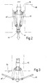
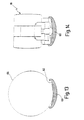
- a first exemplary embodiment shown in perspective in FIG. 1 of a suture aid device is in its entirety provided with the reference number 10.
- the suture aid device 10 has an elongated shaft 12 in the form of a tube 14.
- a handle 16 is provided at the proximal end of the tube 14, the two diametrically opposed, approximately ring-shaped, has finger eyelets 18, 18 'extending in one plane.
- a locking mechanism 20 is provided on the handle 16 has a spring lever 22.
- the spring lever 22 is about a fixed pivot axis on the handle 16 23 pivotally attached and has one at one end Pin 24, which, as will be described later, in corresponding Recesses engages recesses or grooves.
- the spring lever 22 is acted upon by a spring 25 which presses it into the locking or locking position.
- a spring 25 On the end opposite the pin 24 is the spring lever 22 provided with a key, which is not described here in greater detail, which can be operated by a fingertip.
- an actuator 26 in Form of a rod 28 added longitudinally.
- the rod 28 is proximal to the handle 16 End provided with a finger eyelet 30, which is in the same Level as the finger eyelets 18, 18 'extends.
- the flattening 32 shown in FIG. 1 is diametrical opposite flattening also serves as a sliding surface for the pin 24 of the spring lever 22, as the following described in more detail in connection with the mode of operation becomes.
- Incised annular groove 36 At a distance from the flat 32 there is a first proximal to it Incised annular groove 36, the flanks of which are designed as ramps 38 are.
- the relatively narrow groove 36 is proximally followed by a relative one wide groove 40 on, the flanks also as ramps are trained.
- the pin 24 is designed so that it both in the groove 36th and can also snap into the wide groove 40.
- the rod 28 has an angled end 42 on the hinge-shaped joints 44 of a support 46 are included.
- the support 46 consists of two diametrically opposite, approximately rectangular wing plates 48, 48 ', thus pivotally mounted about the angled end 42 of the rod 28 are.
- the central longitudinal axis of the angled end 42 provides thus the hinge axis 45 or the corresponding pivot axis of the wing plates 48, 48 '.
- On the proximal end the side of the suture aid device 10 are the wing plates 48, 48 'centered with one along the longitudinal axis extending guide groove 49 and 49 'provided.
- the wing plates 48, 48 ' are via actuating levers 50, 50' articulated with a flange 51 at the distal end of the shaft 12 connected.
- the operating lever 50 is, like that in particular also in connection with FIGS. 4 and 8 can be seen is, on the one hand articulated with a hinge pin 52 Flange 51 and on the other hand articulated via a hinge pin 54 connected to a side edge of the wing plate 48.
- the distance between hinge axis 45 and hinge pin 54 about a third of the axial length of the wing plate 48 then applies to the articulated connection of the Wing plate 48 'with the operating lever 50'.
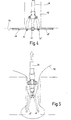
- the different working positions and swivel positions of the Wing plates 48, 48 'are to be based on the image sequence below 2 to 5 are described, the image sequence of 6 to 9 corresponding perspective views of the Pivotal position of the wing plates 48, 48 'shows.
- the surgeon now grips the suturing device 10, pushes two fingers in the finger eyelets 18, 18 ', for example the index finger and middle finger.
- the locking mechanism can now be used with the thumb 20 are solved so that the suturing device 10th with its distal end first into a mini laparotomy 112, For example, in an abdominal wall 110, can be inserted, such as which is shown in Fig. 2.
- the finger eyelet 30 needs this not be taken.
- the diameter of the mini laparotomy 112 is significantly smaller than the radial extension of the unfolded wing plates 48, 48 ', so that they are folded up proximally and assume a V-shaped position as in 2 and 6 is shown.
- the rod 28 is against the force of the spring 34 in the shaft 12 is shifted distally, the finger eyelet 30 thus moves towards the handle 16. This can either be supported by the surgeon, this process but is also from the walls of the mini laparotomy 112 accomplished without injury or injury
- the mini-laparotomy 112 is expanded. The surgeon can, for example, the thumb from the finger eyelet 30 in this Remove the process.
- the locking mechanism 20 After threading 116, the locking mechanism 20 unlocked again and the rod 28 is over the finger eyelet 30, into which the thumb is inserted, pulled proximally.
- the thread 116 can then be knotted and thus the Mini laparotomy can be closed.
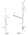
- FIG. 11 Guide rail 60 provided.
- the guide rail 60 has a guide groove 62 to which the suturing aid 10 is attached as shown in FIG. 12 can be.
- the guide rail 60 has an angled one Handle 64 so that both devices, i.e. guide rail 60th and suture aid device 10 held by different hands can be without interfering with each other.
- a scale 68 is provided, on the the insertion depth can be read.
- This cross-sectional profile is designed so that the guide rail 16 along a trocar, as shown in Fig. 13 by the Contour line 66 is indicated, inserted into the body can be.
- the Insertion depth can be checked via the scale 68, the trocar is removed. Then that will Seam aid device 10 attached to the guide groove 62, as in 12 and 14 is shown and in the body or passed through the mini laparotomy 112. This Additional device facilitates handling, especially that atraumatic insertion and insertion of the suture aid device 10.
- the previously described seam aid device 10 is completely off Made of metal and thus as a reusable Instrument designed that is autoclavable.
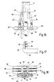
- 15 to 18 is a further embodiment of a Seam aid according to the invention shown that in its Entire is provided with the reference number 70.
- the seam aid device 70 is basically the same as the seam aid device 10 formed, but completely made of plastic, especially made of injection molded plastic parts, thus Manufacture more cost-effectively and if necessary use it as a disposable device
- the seam aid device 70 accordingly has a shaft 72 on, which is designed as a tube 74.
- the pipe is proximal 74 provided with a handle 76, the two finger eyelets 78, 78 ' having.
- an actuator 80 in the form of a longitudinally displaceable Rod 82 added, the proximal with a Finger eyelet 84 is provided.
- the rod 82 has an angled end 86 (see in particular Fig. 17), on the side over flexible plastic bridges 88, 88 'the wing plates 89, 89' molded in one piece are.
- the flexible plastic bridges 88, 88 ' thus form film hinges.
- Two operating levers 90, 90 ' are connected via plastic bridges 92, 92 '(see in particular Fig. 16) hinged to the distal end of tube 74.
- the tube 74 has a corresponding inner contour, like that can be seen from the sectional view of Fig. 18, thus the rod 82 is rotatably received in the tube 94.
- a radial projecting pin 108 is provided, which in a appropriate groove can be used in a guide rail can, to a defined insertion of the suture aid device 70th to reach.
Landscapes
- Health & Medical Sciences (AREA)
- Life Sciences & Earth Sciences (AREA)
- Surgery (AREA)
- Heart & Thoracic Surgery (AREA)
- Engineering & Computer Science (AREA)
- Biomedical Technology (AREA)
- Nuclear Medicine, Radiotherapy & Molecular Imaging (AREA)
- Medical Informatics (AREA)
- Molecular Biology (AREA)
- Animal Behavior & Ethology (AREA)
- General Health & Medical Sciences (AREA)
- Public Health (AREA)
- Veterinary Medicine (AREA)
- Surgical Instruments (AREA)
Description
In einer weiteren Ausgestaltung der Erfindung sind die Aussparungen mit Rampen versehen, die ein erkennbares Einrasten verursachen.
Diese Maßnahme hat den Vorteil, daß das Halten der Führungsschiene bei gleichzeitig angelegtem Nahthilfegerät einfach möglich ist.
- Fig. 1
- eine perspektivische Ansicht eines ersten Ausführungsbeispieles eines Nahthilfegerätes,
- Fig. 2
- eine teilweise schematisierte Ansicht des distalen Endbereiches des Nahthilfegerätes in einer proximal hochgeklappten Arbeitsposition der Auflage beim Durchschieben durch eine Minilaparotomie,
- Fig. 3
- eine der Fig. 2 vergleichbare Darstellung in einer schon seitlich ausgeklappten Zwischenposition der Auflage,
- Fig. 4
- eine den Darstellungen von Fig. 2 und 3 vergleichbare Darstellung in der seitlich vollständig ausgeklappten Arbeitsposition der Auflage,
- Fig. 5
- eine den Darstellungen von Fig. 2 bis 4 vergleichbare Ansicht mit einer nach distal abgeklappten Arbeitsposition der Auflage während des Abziehens aus einer Minilaparotomie,
- Fig. 6
- eine perspektivische Ansicht von proximal nach distal des distalen Endbereiches des Nahthilfegerätes in einer Stellung entsprechend der Stellung von Fig. 2,
- Fig. 7
- eine der Darstellung von Fig. 3 entsprechende perspektivische Darstellung,
- Fig. 8
- eine der Darstellung von Fig. 4 entsprechende perspektivische Darstellung,
- Fig. 9
- eine der Darstellung von Fig. 5 entsprechende perspektivische Darstellung,
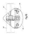
- Fig. 10
- eine Draufsicht von proximal nach distal auf eine Minilaparotomie mit bereits eingesetztem Nahthilfegerät in der Spreizstellung von Fig. 4,
- Fig. 11
- eine Seitenansicht einer Führungsschiene zum Einführen des Nahthilfegerätes in die Minilaparotomie,
- Fig. 12
- eine um 90° verdrehte Seitenansicht der Führungsschiene von Fig. 6 mit angesetztem Nahthilfegerät von Fig. 1,
- Fig. 13
- ein stark vergrößerter Querschnitt der Führungsnut der Führungsschiene von Fig. 11, wobei diese an einen Trokar angelegt ist,
- Fig. 14
- eine der Schnittdarstellung von Fig. 13 vergleichbare Schnittdarstellung mit angelegtem Nahthilfegerät,
- Fig. 15
- eine Seitenansicht eines weiteren Ausführungsbeispiels eines Nahthilfegerätes in Kunststoffversion,
- Fig. 16
- eine vergrößerte Darstellung des Nahthilfegerätes von Fig. 15 im distalen Bereich,
- Fig. 17
- einen Schnitt längs der Linie XVII-XVII in Fig. 16 und
- Fig. 18
- eine der Schnittdarstellung von Fig. 10 vergleichbare Darstellung des Nahthilfegerätes in seitlich ausgeklapptem Zustand.
Claims (17)
- Nahthilfegerät für das Verschließen von Minilaparotomien (112) aus minimal-invasiven chirurgischen Eingriffen, gekennzeichnet durch einen Schaft (12, 72), an dessen distalem Ende zumindest eine seitlich ausschwenkbare flächige Auflage (46) angeordnet ist, mit einem Betätigungselement (26, 80) zum Verschwenken der Auflage (46), wobei die Auflage (46) zwischen einer nach proximal hochgeklappten Arbeitsposition, einer seitlich ausgeklappten Arbeitsposition und einer nach distal abgeklappten Arbeitsposition steuerbar ist.
- Nahthilfegerät nach Anspruch 1, dadurch gekennzeichnet, daß die Auflage (46) zwei diametral gegenüberliegende Flügelplatten (48, 48'; 89, 89') aufweist.
- Nahthilfegerät nach Anspruch 1 oder 2, dadurch gekennzeichnet, daß das Betätigungselement (26, 80) als längs des Schaftes (12, 72) verschiebbarer Stab (28, 82) ausgebildet ist, der distal gelenkig mit der Auflage (46) verbunden ist, wobei die Gelenkachse (45) die Schwenkachse der Auflage (46) darstellt.
- Nahthilfegerät nach einem der Ansprüche 1 bis 3, dadurch gekennzeichnet, daß die Auflage (46) im Abstand zu ihrer Schwenkachse (45) gelenkig mit einem Ende eines Betätigungshebels (50, 50'; 90, 90') verbunden ist, dessen anderes Ende gelenkig mit dem Schaft (12, 72) verbunden ist.
- Nahthilfegerät nach Anspruch 4, dadurch gekennzeichnet, daß der Abstand zwischen der Schwenkachse (45) der Auflage (46) und der Anlenkung des Betätigungshebels (50, 50'; 90, 90') etwa einem Drittel der Gesamtlänge der Auflage (46) entspricht.
- Nahthilfegerät nach einem der Ansprüche 1 bis 5, dadurch gekennzeichnet, daß auf der dem proximalen Ende des Nahthilfegerätes (10, 70) zugewandten Seite der Auflage (46) zumindest eine Führung (49, 49'; 96, 96', 97, 97') für ein Nahtwerkzeug vorgesehen ist.
- Nahthilfegerät nach einem der Ansprüche 1 bis 6, dadurch gekennzeichnet, daß das Betätigungselement (26, 80) verdrehsicher im Schaft (12, 72) aufgenommen ist.
- Nahthilfegerät nach einem der Ansprüche 1 bis 7, dadurch gekennzeichnet, daß das Betätigungselement (26) durch die Kraft einer Feder (34) derart beaufschlagt ist, daß die Auflage (46) aus der nach proximal hochgeklappten Arbeitsposition selbständig in Richtung der seitlich ausgeklappten Arbeitsposition bewegt wird.
- Nahthilfegerät nach Anspruch 8, dadurch gekennzeichnet, daß die Kraft der Feder (34) derart eingestellt ist, daß die Arbeitsauflage (46) nur bis in eine Zwischenposition seitlich ausgeklappt wird, wobei die Zwischenposition etwas vor der vollständig seitlich ausgeklappten Arbeitsposition liegt.
- Nahthilfegerät nach einem der Ansprüche 1 bis 9, dadurch gekennzeichnet, daß am Schaft (12, 72) und/oder am Betätigungselement (26, 80) Orientierungsmerkmale (104, 105, 106) vorgesehen sind, die die jeweilige Schwenkstellung der Auflage anzeigen.
- Nahthilfegerät nach einem der Ansprüche 1 bis 10, dadurch gekennzeichnet, daß ein Feststellmechanismus (20) vorgesehen ist, über den die Auflage (46) in bestimmten Schwenkstellungen feststellbar ist.
- Nahthilfegerät nach Anspruch 11, dadurch gekennzeichnet, daß der Feststellmechanismus (20) als ein am Schaft (12, 72) schwenkbar gelagerter Federhebel (22) ausgebildet ist, der ein Rastelement (24, 102) aufweist, das in entsprechende Aussparungen (36, 40; 104, 105, 106) am Betätigungselement (26, 80) eingreift.
- Nahthilfegerät nach Anspruch 12, dadurch gekennzeichnet, daß die Aussparung (36, 40; 104, 105, 106) mit Rampen (38) versehen sind, die ein erkennbares Einrasten verursachen.
- Nahthilfegerät nach einem der Ansprüche 1 bis 13, dadurch gekennzeichnet, daß zu seiner Einführung in eine Minilaparotomie eine spezielle Führungsschiene (60) vorgesehen ist.
- Nahthilfegerät nach Anspruch 14, dadurch gekennzeichnet, daß die Führungsschiene (60) einen abgewinkelten Griff (64) aufweist.
- Nahthilfegerät nach Anspruch 14 oder 15, dadurch gekennzeichnet, daß die Führungsschiene eine Führungsnut für einen Führungszapfen (108) am distalen Ende des Betätigungselementes aufweist, der eine spürbare Führung und Steuerung der Eindringtiefe des Nahthilfegerätes, bezogen auf die Eindringtiefe der Führungsschiene, erlaubt.
- Nahthilfegerät nach einem der Ansprüche 14 bis 16, dadurch gekennzeichnet, daß die Führungsschiene mit einer Skala (68) versehen ist.
Applications Claiming Priority (5)
| Application Number | Priority Date | Filing Date | Title |
|---|---|---|---|
| DE19618885 | 1996-05-10 | ||
| DE19618885 | 1996-05-10 | ||
| DE19635354A DE19635354A1 (de) | 1996-05-10 | 1996-08-31 | Nahthilfegerät für minimal invasive chirurgische Eingriffe |
| DE19635354 | 1996-08-31 | ||
| PCT/EP1997/002365 WO1997042880A1 (de) | 1996-05-10 | 1997-05-08 | Nahthilfegerät |
Publications (2)
| Publication Number | Publication Date |
|---|---|
| EP0902649A1 EP0902649A1 (de) | 1999-03-24 |
| EP0902649B1 true EP0902649B1 (de) | 2001-09-05 |
Family
ID=26025591
Family Applications (1)
| Application Number | Title | Priority Date | Filing Date |
|---|---|---|---|
| EP97923027A Expired - Lifetime EP0902649B1 (de) | 1996-05-10 | 1997-05-08 | Nahthilfegerät |
Country Status (4)
| Country | Link |
|---|---|
| US (1) | US6296648B1 (de) |
| EP (1) | EP0902649B1 (de) |
| JP (1) | JP3912620B2 (de) |
| WO (1) | WO1997042880A1 (de) |
Families Citing this family (19)
| Publication number | Priority date | Publication date | Assignee | Title |
|---|---|---|---|---|
| US6626914B2 (en) * | 1996-05-17 | 2003-09-30 | Jomed N.V. | Graft connector, an introducer therefor and a method of making a branch connection |
| US6814421B2 (en) * | 2002-10-24 | 2004-11-09 | Hewlett-Packard Development Company, L.P. | Printing device and method |
| EP1749479A1 (de) * | 2005-08-02 | 2007-02-07 | Marco Gandini | Retraktor |
| US20110082475A1 (en) * | 2009-10-01 | 2011-04-07 | Tyco Healthcare Group Lp | Wound closure device including ferrule ejector system |
| US8906042B2 (en) | 2010-07-29 | 2014-12-09 | Covidien Lp | Wound closure device including mesh barrier |
| US9327160B2 (en) | 2011-03-22 | 2016-05-03 | Jake Samuel Tauriainen | Modular self-spotting safety device for weightlifting |
| JP5963559B2 (ja) | 2012-06-18 | 2016-08-03 | 日本コヴィディエン株式会社 | 医療用縫合具 |
| US10426472B2 (en) | 2013-08-02 | 2019-10-01 | Covidien Lp | Devices, systems, and methods for wound closure |
| US10070851B2 (en) | 2013-08-02 | 2018-09-11 | Covidien Lp | Devices, systems, and methods for wound closure |
| JP6393142B2 (ja) * | 2014-10-02 | 2018-09-19 | 株式会社九研 | 縫合手術用起子 |
| CN106308883A (zh) * | 2015-06-30 | 2017-01-11 | 李楠 | 一种开腹手术用下腔静脉根部血管解剖分离钳 |
| CN106551709A (zh) * | 2015-09-30 | 2017-04-05 | 爱微捷成都医疗科技有限公司 | 腹壁缝合器 |
| US10188381B2 (en) | 2015-11-20 | 2019-01-29 | Dura Tap Llc | Suture repair device |
| CN108289659B (zh) | 2015-11-25 | 2022-06-28 | 爪医疗有限公司 | 组织接合装置、系统和方法 |
| CN107625539B (zh) * | 2017-10-12 | 2020-04-17 | 高密市卫生学校 | 一种口腔扩张器 |
| US11213288B2 (en) | 2018-05-02 | 2022-01-04 | Covidien Lp | Port site closure instrument |
| US11234690B2 (en) | 2018-05-02 | 2022-02-01 | Covidien Lp | Method and device for closing a port site incision |
| CN111096769B (zh) * | 2019-12-31 | 2024-12-10 | 清华大学 | 用于空腔脏器的辅助缝合装置 |
| CN111588485B (zh) * | 2020-06-04 | 2021-11-09 | 王冬 | 一种胸腹腔小切口缝合辅助器 |
Family Cites Families (13)
| Publication number | Priority date | Publication date | Assignee | Title |
|---|---|---|---|---|
| DE640126C (de) * | 1934-07-29 | 1936-12-24 | Bruno Loewel Dr | Trokar |
| US4836205A (en) | 1988-03-21 | 1989-06-06 | Barrett Gene R | Grasper-stitcher device for arthroscopic anterior cruciate ligament repair |
| DE4021153A1 (de) | 1990-07-03 | 1992-01-16 | Wolf Gmbh Richard | Organmanipulator |
| US5176128A (en) | 1991-01-24 | 1993-01-05 | Andrese Craig A | Organ retractor |
| DE4210724C1 (en) | 1992-04-01 | 1993-07-22 | Rema-Medizintechnik Gmbh, 7201 Duerbheim, De | Surgical instrument with expander in shaft portion - has expanding member mounting eccentrical on pinion meshing with central gear on shaft passing through stem |
| US5351679A (en) | 1992-08-17 | 1994-10-04 | Ilya Mayzels | Surgical endoscopic retractor instrument |
| US5364408A (en) * | 1992-09-04 | 1994-11-15 | Laurus Medical Corporation | Endoscopic suture system |
| US5507755A (en) * | 1993-08-03 | 1996-04-16 | Origin Medsystems, Inc. | Apparatus and method for closing puncture wounds |
| US5391182A (en) | 1993-08-03 | 1995-02-21 | Origin Medsystems, Inc. | Apparatus and method for closing puncture wounds |
| US5474568A (en) | 1993-10-08 | 1995-12-12 | United States Surgical Corporation | Instrument for closing trocar puncture wounds |
| DE4415521C2 (de) | 1994-05-04 | 2003-01-30 | Storz Reling Sybill Gesamthand | Instrument zum Einsatz bei endoskopischen Eingriffen |
| US5573495A (en) * | 1994-08-19 | 1996-11-12 | Flexbar Machine Corp. | Abdominal wall elevator device employing rotatable arms |
| DE19635354A1 (de) | 1996-05-10 | 1997-11-20 | Storz Karl Gmbh & Co | Nahthilfegerät für minimal invasive chirurgische Eingriffe |
-
1997
- 1997-05-08 EP EP97923027A patent/EP0902649B1/de not_active Expired - Lifetime
- 1997-05-08 WO PCT/EP1997/002365 patent/WO1997042880A1/de not_active Ceased
- 1997-05-08 US US09/180,634 patent/US6296648B1/en not_active Expired - Fee Related
- 1997-05-08 JP JP54049197A patent/JP3912620B2/ja not_active Expired - Fee Related
Also Published As
| Publication number | Publication date |
|---|---|
| WO1997042880A1 (de) | 1997-11-20 |
| JP2000510015A (ja) | 2000-08-08 |
| JP3912620B2 (ja) | 2007-05-09 |
| US6296648B1 (en) | 2001-10-02 |
| EP0902649A1 (de) | 1999-03-24 |
Similar Documents
| Publication | Publication Date | Title |
|---|---|---|
| EP0902649B1 (de) | Nahthilfegerät | |
| DE69622969T2 (de) | Wundverschlussvorrichtung | |
| DE69309509T2 (de) | Einrichtung zur Durchführung endoskopischer Chirurgie | |
| DE69632547T2 (de) | Trokaranordnung | |
| DE60225619T2 (de) | Subkutane Nähvorrichtung zum Schliessen einer Öffnung der Bauchdecke eines Patienten | |
| DE69416477T2 (de) | Applikator für blattförmiges chirurgisches Material | |
| DE69930104T2 (de) | Endoskopisches nähsystem | |
| DE69735501T2 (de) | Systeme und instrumente zur minimal invasiven chirurgie | |
| DE60304007T2 (de) | Chirurgischer Klammer und Befestigungsgerät dafür | |
| DE19848958B4 (de) | Vorrichtung zum Manipulieren von Nahtmaterial während endoskopischer chirurgischer Prozeduren | |
| DE69314140T2 (de) | Endoskopisches, chirurgisches Instrument | |
| DE69314255T2 (de) | Gerät zur Entfaltung eines chirurgischen Elementes | |
| DE19906260C2 (de) | Dissektionsretraktor für die Gefäßentnahme | |
| DE4306277C2 (de) | Operationsmarkierungswerkzeug | |
| DE69636839T2 (de) | Endochirurgisches instrument mit einem radialbeweglichem griff | |
| EP0742695B1 (de) | Mikrochirurgisches instrument | |
| DE102012221109B4 (de) | Chirurgisches Instrument und Griff für ein chirurgisches Instrument | |
| EP0684012A2 (de) | Faden zum Anlegen einer chirurgischen Naht, Übergabehalter und chirurgisches Nähinstrument | |
| DE29909688U1 (de) | Instrument zur chirurgischen Ligation | |
| DE9290082U1 (de) | Instrumentenplaziervorrichtung | |
| EP1083834B1 (de) | Vorrichtung zum schaffen eines transkutanen zuganges zu einem körperinneren hohlorgan | |
| WO1999049794A1 (de) | Chirurgisches instrument mit einem durchgehenden hohlkanal für ein weiteres instrument | |
| EP1601293B1 (de) | Medizinisches instrumentarium zum schaffen eines operativen arbeitsraumes bei kieferoperationen | |
| WO2014067840A1 (de) | Atrium-retraktor | |
| DE19707374C2 (de) | Medizinischer Dissektionsspatel mit spreizbaren Spatelmaulteilen |
Legal Events
| Date | Code | Title | Description |
|---|---|---|---|
| PUAI | Public reference made under article 153(3) epc to a published international application that has entered the european phase |
Free format text: ORIGINAL CODE: 0009012 |
|
| 17P | Request for examination filed |
Effective date: 19981125 |
|
| AK | Designated contracting states |
Kind code of ref document: A1 Designated state(s): DE FR GB IT |
|
| RAP1 | Party data changed (applicant data changed or rights of an application transferred) |
Owner name: KARL STORZ GMBH & CO. KG |
|
| GRAG | Despatch of communication of intention to grant |
Free format text: ORIGINAL CODE: EPIDOS AGRA |
|
| GRAG | Despatch of communication of intention to grant |
Free format text: ORIGINAL CODE: EPIDOS AGRA |
|
| GRAH | Despatch of communication of intention to grant a patent |
Free format text: ORIGINAL CODE: EPIDOS IGRA |
|
| 17Q | First examination report despatched |
Effective date: 20001103 |
|
| GRAH | Despatch of communication of intention to grant a patent |
Free format text: ORIGINAL CODE: EPIDOS IGRA |
|
| GRAA | (expected) grant |
Free format text: ORIGINAL CODE: 0009210 |
|
| AK | Designated contracting states |
Kind code of ref document: B1 Designated state(s): DE FR GB IT |
|
| REF | Corresponds to: |
Ref document number: 59704540 Country of ref document: DE Date of ref document: 20011011 |
|
| REG | Reference to a national code |
Ref country code: GB Ref legal event code: IF02 |
|
| GBT | Gb: translation of ep patent filed (gb section 77(6)(a)/1977) |
Effective date: 20011212 |
|
| ET | Fr: translation filed | ||
| PLBE | No opposition filed within time limit |
Free format text: ORIGINAL CODE: 0009261 |
|
| STAA | Information on the status of an ep patent application or granted ep patent |
Free format text: STATUS: NO OPPOSITION FILED WITHIN TIME LIMIT |
|
| 26N | No opposition filed | ||
| PGFP | Annual fee paid to national office [announced via postgrant information from national office to epo] |
Ref country code: GB Payment date: 20120423 Year of fee payment: 16 Ref country code: FR Payment date: 20120625 Year of fee payment: 16 |
|
| PGFP | Annual fee paid to national office [announced via postgrant information from national office to epo] |
Ref country code: IT Payment date: 20120421 Year of fee payment: 16 |
|
| GBPC | Gb: european patent ceased through non-payment of renewal fee |
Effective date: 20130508 |
|
| PG25 | Lapsed in a contracting state [announced via postgrant information from national office to epo] |
Ref country code: IT Free format text: LAPSE BECAUSE OF NON-PAYMENT OF DUE FEES Effective date: 20130508 |
|
| REG | Reference to a national code |
Ref country code: FR Ref legal event code: ST Effective date: 20140131 |
|
| PG25 | Lapsed in a contracting state [announced via postgrant information from national office to epo] |
Ref country code: GB Free format text: LAPSE BECAUSE OF NON-PAYMENT OF DUE FEES Effective date: 20130508 |
|
| PG25 | Lapsed in a contracting state [announced via postgrant information from national office to epo] |
Ref country code: FR Free format text: LAPSE BECAUSE OF NON-PAYMENT OF DUE FEES Effective date: 20130531 |
|
| PGFP | Annual fee paid to national office [announced via postgrant information from national office to epo] |
Ref country code: DE Payment date: 20140424 Year of fee payment: 18 |
|
| REG | Reference to a national code |
Ref country code: DE Ref legal event code: R119 Ref document number: 59704540 Country of ref document: DE |
|
| PG25 | Lapsed in a contracting state [announced via postgrant information from national office to epo] |
Ref country code: DE Free format text: LAPSE BECAUSE OF NON-PAYMENT OF DUE FEES Effective date: 20151201 |