EP0902649B1 - Suturing aid - Google Patents
Suturing aid Download PDFInfo
- Publication number
- EP0902649B1 EP0902649B1 EP97923027A EP97923027A EP0902649B1 EP 0902649 B1 EP0902649 B1 EP 0902649B1 EP 97923027 A EP97923027 A EP 97923027A EP 97923027 A EP97923027 A EP 97923027A EP 0902649 B1 EP0902649 B1 EP 0902649B1
- Authority
- EP
- European Patent Office
- Prior art keywords
- support
- aid according
- suturing
- suturing aid
- shaft
- Prior art date
- Legal status (The legal status is an assumption and is not a legal conclusion. Google has not performed a legal analysis and makes no representation as to the accuracy of the status listed.)
- Expired - Lifetime
Links
- 230000007246 mechanism Effects 0.000 claims description 13
- 230000035515 penetration Effects 0.000 claims description 4
- 230000000694 effects Effects 0.000 claims description 2
- 210000003815 abdominal wall Anatomy 0.000 description 25
- 238000002350 laparotomy Methods 0.000 description 24
- 208000027418 Wounds and injury Diseases 0.000 description 22
- 206010052428 Wound Diseases 0.000 description 17
- 230000008901 benefit Effects 0.000 description 17
- 210000003811 finger Anatomy 0.000 description 16
- 238000003780 insertion Methods 0.000 description 12
- 230000037431 insertion Effects 0.000 description 12
- 210000000056 organ Anatomy 0.000 description 9
- 230000000007 visual effect Effects 0.000 description 6
- 230000006378 damage Effects 0.000 description 5
- 208000014674 injury Diseases 0.000 description 5
- 238000009958 sewing Methods 0.000 description 5
- 210000001519 tissue Anatomy 0.000 description 5
- 238000000034 method Methods 0.000 description 4
- 230000008569 process Effects 0.000 description 4
- 229920003023 plastic Polymers 0.000 description 3
- 239000004033 plastic Substances 0.000 description 3
- 238000001356 surgical procedure Methods 0.000 description 3
- 210000003813 thumb Anatomy 0.000 description 3
- 230000007704 transition Effects 0.000 description 3
- 210000001835 viscera Anatomy 0.000 description 3
- 241000270923 Hesperostipa comata Species 0.000 description 2
- 210000001015 abdomen Anatomy 0.000 description 2
- 238000010276 construction Methods 0.000 description 2
- 238000006073 displacement reaction Methods 0.000 description 2
- 239000004744 fabric Substances 0.000 description 2
- 229920002457 flexible plastic Polymers 0.000 description 2
- 210000000936 intestine Anatomy 0.000 description 2
- 210000003205 muscle Anatomy 0.000 description 2
- 230000007480 spreading Effects 0.000 description 2
- 238000003892 spreading Methods 0.000 description 2
- 210000000689 upper leg Anatomy 0.000 description 2
- 208000009344 Penetrating Wounds Diseases 0.000 description 1
- 210000000683 abdominal cavity Anatomy 0.000 description 1
- 230000003187 abdominal effect Effects 0.000 description 1
- 230000004323 axial length Effects 0.000 description 1
- 238000004140 cleaning Methods 0.000 description 1
- 230000006735 deficit Effects 0.000 description 1
- 230000003670 easy-to-clean Effects 0.000 description 1
- 238000011010 flushing procedure Methods 0.000 description 1
- 210000004247 hand Anatomy 0.000 description 1
- 238000002347 injection Methods 0.000 description 1
- 239000007924 injection Substances 0.000 description 1
- 230000002452 interceptive effect Effects 0.000 description 1
- 210000002414 leg Anatomy 0.000 description 1
- 238000004519 manufacturing process Methods 0.000 description 1
- 239000002184 metal Substances 0.000 description 1
- 238000002324 minimally invasive surgery Methods 0.000 description 1
- 239000002991 molded plastic Substances 0.000 description 1
- 206010033675 panniculitis Diseases 0.000 description 1
- 210000004303 peritoneum Anatomy 0.000 description 1
- 231100000241 scar Toxicity 0.000 description 1
- 210000004304 subcutaneous tissue Anatomy 0.000 description 1
- 238000011477 surgical intervention Methods 0.000 description 1
Images


Classifications
-
- A—HUMAN NECESSITIES
- A61—MEDICAL OR VETERINARY SCIENCE; HYGIENE
- A61B—DIAGNOSIS; SURGERY; IDENTIFICATION
- A61B17/00—Surgical instruments, devices or methods
- A61B17/04—Surgical instruments, devices or methods for suturing wounds; Holders or packages for needles or suture materials
- A61B17/0469—Suturing instruments for use in minimally invasive surgery, e.g. endoscopic surgery
-
- A—HUMAN NECESSITIES
- A61—MEDICAL OR VETERINARY SCIENCE; HYGIENE
- A61B—DIAGNOSIS; SURGERY; IDENTIFICATION
- A61B17/00—Surgical instruments, devices or methods
- A61B17/02—Surgical instruments, devices or methods for holding wounds open, e.g. retractors; Tractors
- A61B17/0281—Abdominal wall lifters
-
- A—HUMAN NECESSITIES
- A61—MEDICAL OR VETERINARY SCIENCE; HYGIENE
- A61B—DIAGNOSIS; SURGERY; IDENTIFICATION
- A61B17/00—Surgical instruments, devices or methods
- A61B17/04—Surgical instruments, devices or methods for suturing wounds; Holders or packages for needles or suture materials
- A61B17/0482—Needle or suture guides
-
- A—HUMAN NECESSITIES
- A61—MEDICAL OR VETERINARY SCIENCE; HYGIENE
- A61B—DIAGNOSIS; SURGERY; IDENTIFICATION
- A61B17/00—Surgical instruments, devices or methods
- A61B17/28—Surgical forceps
- A61B17/29—Forceps for use in minimally invasive surgery
- A61B17/2909—Handles
- A61B2017/2911—Handles rings
-
- A—HUMAN NECESSITIES
- A61—MEDICAL OR VETERINARY SCIENCE; HYGIENE
- A61B—DIAGNOSIS; SURGERY; IDENTIFICATION
- A61B17/00—Surgical instruments, devices or methods
- A61B17/34—Trocars; Puncturing needles
- A61B2017/348—Means for supporting the trocar against the body or retaining the trocar inside the body
- A61B2017/3482—Means for supporting the trocar against the body or retaining the trocar inside the body inside
- A61B2017/3484—Anchoring means, e.g. spreading-out umbrella-like structure
-
- A—HUMAN NECESSITIES
- A61—MEDICAL OR VETERINARY SCIENCE; HYGIENE
- A61B—DIAGNOSIS; SURGERY; IDENTIFICATION
- A61B90/00—Instruments, implements or accessories specially adapted for surgery or diagnosis and not covered by any of the groups A61B1/00 - A61B50/00, e.g. for luxation treatment or for protecting wound edges
- A61B90/06—Measuring instruments not otherwise provided for
- A61B2090/062—Measuring instruments not otherwise provided for penetration depth
Definitions
- the invention relates to a seam aid device for closing of mini laparotomies from minimally invasive surgical Interventions.
- Trocar sleeves in which a pointed mandrel, a so-called Trocar thorn is picked up, for example, through the abdominal wall introduced into the abdomen.
- the trocar mandrel can then through the sleeve endoscopes and surgical instruments be brought into the operating area.
- sleeve endoscopes can then through the sleeve endoscopes and surgical instruments be brought into the operating area.
- Under visual control can, therefore, only be opened with small stitches Abdominal cavity, to be operated on.
- the instruments are used and finally the trocar sleeve removed. Remaining residual small, but the entire abdominal wall, i.e. the skin that Subcutaneous tissue, the muscle skin, the muscles and the peritoneum penetrating wounds, so-called mini laparotomies.
- mini-laparotomies were originally used in this surgical technique not closed, which leads to breakage, possibly with entrapping of the intestine or parts of the intestine, led, comparable to a inguinal, umbilical or scar fracture. Therefore instruments were developed with With the help of which mini laparotomies can be closed.
- This instrument has a long shaft on which proximal end a scissor-like handle is arranged. In the area of the distal end, provided approximately semicircular bent needles Wear thread.
- the long thin shaft is cut through the trocar wound pushed through, the needles are swung in and do not protrude radially beyond the contour of the shaft. After insertion the needles are extended laterally into the body and penetrate from the bottom of the abdominal wall, pull the thread along until the tip of the curved needle again reaches the shaft body and clicks into place. At the The actual bent needle body loosens back of the snapped-in tip and the one held by it Thread. The device is then removed and the Thread knotted.
- This instrument works as an actual suturing device.
- the disadvantage is that the surgeon cannot determine when the shaft or its distal area just the has penetrated the entire abdominal wall, but not yet in other organs under the abdominal wall have penetrated is.
- DE-C-4 210 724 describes a surgical actuation device known, which has an elongated shaft part, from the expansion parts in one plane, perpendicular to the Shaft axis, can be extended laterally. Moving the in a radial plane expandable parts is made by Rotating a shaft passing through the shaft part. In one version is provided at the outer tips of the Spreading parts to provide upstanding needles that cover the abdominal wall can pierce. This device also works as Seam device and involves the risk of radial Extending surrounding organs damaged in a radial plane can hurt.
- an organ manipulator which an expansion body from a multi-joint lever system has articulated arms pivotally connected to one another, from a stretched position for insertion into the Body cavity can be moved into a spread position, whereby the articulated arms can be converted into a triangular flat structure are.
- This organ manipulator is used exclusively to expose organs in a body cavity.
- DE-A-640 126 describes a trocar with a shaft, at its distal end two laterally swiveling ones Legs are arranged.
- An actuating element is used for pivoting the thigh, the thigh between one side unfolded working position and a proximally folded up position Working position are controllable.
- US-A-5 573 495 discloses a device for lifting the abdominal wall described that a shaft with two laterally swiveling flat supports and an actuating element for pivoting which has requirements. The requirements are between one folded down distally and one unfolded laterally Controllable working position.
- the object of the present invention is therefore an auxiliary device to close mini-laparotomies to create the Surgeon making the suture easier and injuries prevented when closing the mini laparotomies.
- a sewing aid device that has a shaft, at least at its distal end a laterally swiveling flat support is arranged is, as well as with an actuating element for pivoting the pad, the pad between one proximally folded up working position, one folded out to the side Working position and one folded down distally Working position is controllable.
- any flat structure is understood to be it is plate-like, plate-like or also rusty or lattice-like Constructions that ultimately, for example, to the Underside of an abdominal wall can be created.
- laterally swing out in the sense of the present Invention means that the support from the longitudinal axis of the shaft are moved sideways or folded out can.
- proximally folded up working position is understood to be a position in which, from distal to proximal seen along the shaft axis, the free outer end of the Rest closer to the proximal end than its pivot axis.
- laterally unfolded working position is understood a position of the edition, in the Area with respect to the shaft axis at an angle of approximately Is 90 °.
- distal folded working position is used understood a swivel position in which the support opposite the first mentioned proximally raised working position has been pivoted by more than 90 °, i.e. outer end, seen from distal to proximal, under their Swivel axis comes to rest.
- the seam aid can in this Position are moved somewhat away from the body, causing the Then rest flat on the underside of the abdominal wall or of the tissue section through which the wound channel extends.
- This lifting can then be used to sew the fabric layer of underlying body organs, for example a stitching of an abdominal wall, lifted from the bowels become.
- a needle and thread from the outside can be inserted along the shaft, until it reaches this meet the edition.
- Dechamps hook worked which is a corkscrew-like structure is, it can pass through the wound channel along the Shaft of the suture aid device can be wound until its Top meets the edition.
- the hook since it also carries the thread, so from the bottom through the abdominal wall be driven that at the desired location Seam is put. Without visual control, it is ensured that the Dechamps hook or other needle hook is not penetrate too deeply inside the body and accidentally Sew internal organs to the underside of the abdominal wall.
- the seam aid device itself does not work as a seam device but helps or supports known seam devices, such as. the creation of a seam with a Dechamps hook.
- the suture aid can be removed, whereby the support is folded distally, i.e. towards the inside of the body becomes.
- This folding has the significant advantage that not one "Folding back" into the superscript position is done there is a risk that between the fold-up edition and shaft tissue parts or possibly the thread or other is pinched, but from the bottom of the to sewing tissue is pivoted away directed.
- the lifting or the withdrawal of the shaft and the distally directed Swiveling movement can take place synchronously, so that immediately at the start of pulling off the seam aid device Section, i.e. the section of the support in the area of the articulation point to the shaft into which the wound channel is drawn, thus only a relatively small area of the edition Underside of the abdominal wall moved away towards the inside of the body the risk of injury is excluded is. Body parts near the pad are covered by this Swiveling movement from the underside of the fabric layer to be sewn moved away, thus eliminating the risk that parts are accidentally drawn into the wound channel.
- This Process enables the surgeon without precise visual control at an exact location and without impairment to suture surrounding organs.
- This Process does not require the high attention of an experienced Operators, but can also be less experienced or trained persons.
- the actuating element designed as a rod that can be moved along the shaft, which is articulated distally to the support, wherein the hinge axis represents the pivot axis of the support.
- this measure has the constructive advantage that with a few simple, and therefore easy to clean Components that ultimately come in one extremely slim design of the seam aid device results.
- This measure has the advantage that the lever arrangement the axial displacement of the actuator along the Shaft in the desired swivel movement of the Edition is implemented.
- the Distance between the pivot axis of the support and the linkage of the lever in about a third of the total length of the Edition.
- This lever geometry enables functionally reliable implementation the displacement movement of the actuating element in the pivoting movement the edition without much effort.
- the proximal end of the suture aid facing side of the Support provided at least one guide for a seam tool.
- This measure has the advantage that the seam tool, if there is has reached the contact surface, moved back and forth a little until it is in the guide, e.g. a guide groove, entry. The surgeon senses this and then knows that the seam tool at a certain point on the support located. This allows him to align the seam tool the place to be sewn and without visual control place the thread exactly at the tip of the seam tool.
- the actuating element non-rotatably attached in the shaft.
- This measure has the advantage that the actuator in a very specific defined rotational position to the shaft remains, so the surgeon knows in which position or in what extent the edition is, itself when it is pushed into the body and by the surgeon is no longer visible.
- the actuating element acted upon by the force of a spring that the support from the proximally folded up working position independently in the direction of the laterally unfolded Working position is moved.
- This most preferred embodiment has the considerable one Advantage that the pad after going through the wound canal was pushed through, swings out sideways independently, whereby the actuator is also moved. This can the surgeon recognize from the outside, so that he knows exactly that he has now pushed the pad through the wound canal. This ensures that the Seam aid is not accidentally driven too far.
- the force the spring adjusted so that the work rest only up is folded out laterally into an intermediate position, the Intermediate position slightly in front of the fully extended one Working position.
- This measure has the advantage that the surgeon, after he has recognized that the folded-up pad is the wound channel has passed through, now by a slight withdrawal of the suture aid device in the desired, mostly around can bring exactly 90 ° laterally unfolded working position, in which this can then be determined.
- a locking mechanism provided over which the work pad in certain pivot positions can be determined.
- This measure has the advantage that the locking mechanism the edition, especially in its laterally swung out Working position, is noticeable, so that then the further manipulations, such as the setting and laying of the Thread with a Dechamps hook, can be carried out without the relative position between the support and the shaft changes.
- the locking mechanism is as a pivotally mounted on the shaft Spring lever formed which has a latching element which in engages corresponding recesses on the actuator.
- the locking mechanism is easy to operate, that is to say it can be closed or released, but that it can also be recognized which position is currently being determined.
- the cutouts are provided with ramps, which cause a noticeable snap-in.
- a special guide rail is provided.
- This measure has the advantage that the seam aid device is targeted inserted or carried out along the guide in the wound channel can be.
- the guide rail has an angled handle. This measure has the advantage that it is easily possible to hold the guide rail with a sewing aid device applied at the same time.
- the guide rail has a guide groove for a guide pin on distal end of the actuator, which is a noticeable Management and control of the penetration depth of the seam aid device permitted in relation to the depth of penetration of the guide rail.
- This measure has the advantage that a very defined leadership and control possible when inserting the seam aid device is.
- the Guide rail on a scale.
- This measure has the advantage that the insertion depth is on the scale the guide rail can be checked.
- the Insertion depth of the trocar can be recognized and recorded and then insert the guide rail accordingly. This depends on the body type of the patient. This ensures that the insertion no organs are injured on the guide rail.
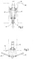
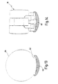
- a first exemplary embodiment shown in perspective in FIG. 1 of a suture aid device is in its entirety provided with the reference number 10.
- the suture aid device 10 has an elongated shaft 12 in the form of a tube 14.
- a handle 16 is provided at the proximal end of the tube 14, the two diametrically opposed, approximately ring-shaped, has finger eyelets 18, 18 'extending in one plane.
- a locking mechanism 20 is provided on the handle 16 has a spring lever 22.
- the spring lever 22 is about a fixed pivot axis on the handle 16 23 pivotally attached and has one at one end Pin 24, which, as will be described later, in corresponding Recesses engages recesses or grooves.
- the spring lever 22 is acted upon by a spring 25 which presses it into the locking or locking position.
- a spring 25 On the end opposite the pin 24 is the spring lever 22 provided with a key, which is not described here in greater detail, which can be operated by a fingertip.
- an actuator 26 in Form of a rod 28 added longitudinally.
- the rod 28 is proximal to the handle 16 End provided with a finger eyelet 30, which is in the same Level as the finger eyelets 18, 18 'extends.
- the flattening 32 shown in FIG. 1 is diametrical opposite flattening also serves as a sliding surface for the pin 24 of the spring lever 22, as the following described in more detail in connection with the mode of operation becomes.
- Incised annular groove 36 At a distance from the flat 32 there is a first proximal to it Incised annular groove 36, the flanks of which are designed as ramps 38 are.
- the relatively narrow groove 36 is proximally followed by a relative one wide groove 40 on, the flanks also as ramps are trained.
- the pin 24 is designed so that it both in the groove 36th and can also snap into the wide groove 40.
- the rod 28 has an angled end 42 on the hinge-shaped joints 44 of a support 46 are included.
- the support 46 consists of two diametrically opposite, approximately rectangular wing plates 48, 48 ', thus pivotally mounted about the angled end 42 of the rod 28 are.
- the central longitudinal axis of the angled end 42 provides thus the hinge axis 45 or the corresponding pivot axis of the wing plates 48, 48 '.
- On the proximal end the side of the suture aid device 10 are the wing plates 48, 48 'centered with one along the longitudinal axis extending guide groove 49 and 49 'provided.
- the wing plates 48, 48 ' are via actuating levers 50, 50' articulated with a flange 51 at the distal end of the shaft 12 connected.
- the operating lever 50 is, like that in particular also in connection with FIGS. 4 and 8 can be seen is, on the one hand articulated with a hinge pin 52 Flange 51 and on the other hand articulated via a hinge pin 54 connected to a side edge of the wing plate 48.
- the distance between hinge axis 45 and hinge pin 54 about a third of the axial length of the wing plate 48 then applies to the articulated connection of the Wing plate 48 'with the operating lever 50'.
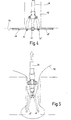
- the different working positions and swivel positions of the Wing plates 48, 48 'are to be based on the image sequence below 2 to 5 are described, the image sequence of 6 to 9 corresponding perspective views of the Pivotal position of the wing plates 48, 48 'shows.
- the surgeon now grips the suturing device 10, pushes two fingers in the finger eyelets 18, 18 ', for example the index finger and middle finger.
- the locking mechanism can now be used with the thumb 20 are solved so that the suturing device 10th with its distal end first into a mini laparotomy 112, For example, in an abdominal wall 110, can be inserted, such as which is shown in Fig. 2.
- the finger eyelet 30 needs this not be taken.
- the diameter of the mini laparotomy 112 is significantly smaller than the radial extension of the unfolded wing plates 48, 48 ', so that they are folded up proximally and assume a V-shaped position as in 2 and 6 is shown.
- the rod 28 is against the force of the spring 34 in the shaft 12 is shifted distally, the finger eyelet 30 thus moves towards the handle 16. This can either be supported by the surgeon, this process but is also from the walls of the mini laparotomy 112 accomplished without injury or injury
- the mini-laparotomy 112 is expanded. The surgeon can, for example, the thumb from the finger eyelet 30 in this Remove the process.
- the locking mechanism 20 After threading 116, the locking mechanism 20 unlocked again and the rod 28 is over the finger eyelet 30, into which the thumb is inserted, pulled proximally.
- the thread 116 can then be knotted and thus the Mini laparotomy can be closed.
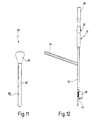
- FIG. 11 Guide rail 60 provided.
- the guide rail 60 has a guide groove 62 to which the suturing aid 10 is attached as shown in FIG. 12 can be.
- the guide rail 60 has an angled one Handle 64 so that both devices, i.e. guide rail 60th and suture aid device 10 held by different hands can be without interfering with each other.
- a scale 68 is provided, on the the insertion depth can be read.
- This cross-sectional profile is designed so that the guide rail 16 along a trocar, as shown in Fig. 13 by the Contour line 66 is indicated, inserted into the body can be.
- the Insertion depth can be checked via the scale 68, the trocar is removed. Then that will Seam aid device 10 attached to the guide groove 62, as in 12 and 14 is shown and in the body or passed through the mini laparotomy 112. This Additional device facilitates handling, especially that atraumatic insertion and insertion of the suture aid device 10.
- the previously described seam aid device 10 is completely off Made of metal and thus as a reusable Instrument designed that is autoclavable.
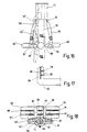
- 15 to 18 is a further embodiment of a Seam aid according to the invention shown that in its Entire is provided with the reference number 70.
- the seam aid device 70 is basically the same as the seam aid device 10 formed, but completely made of plastic, especially made of injection molded plastic parts, thus Manufacture more cost-effectively and if necessary use it as a disposable device
- the seam aid device 70 accordingly has a shaft 72 on, which is designed as a tube 74.
- the pipe is proximal 74 provided with a handle 76, the two finger eyelets 78, 78 ' having.
- an actuator 80 in the form of a longitudinally displaceable Rod 82 added, the proximal with a Finger eyelet 84 is provided.
- the rod 82 has an angled end 86 (see in particular Fig. 17), on the side over flexible plastic bridges 88, 88 'the wing plates 89, 89' molded in one piece are.
- the flexible plastic bridges 88, 88 ' thus form film hinges.
- Two operating levers 90, 90 ' are connected via plastic bridges 92, 92 '(see in particular Fig. 16) hinged to the distal end of tube 74.
- the tube 74 has a corresponding inner contour, like that can be seen from the sectional view of Fig. 18, thus the rod 82 is rotatably received in the tube 94.
- a radial projecting pin 108 is provided, which in a appropriate groove can be used in a guide rail can, to a defined insertion of the suture aid device 70th to reach.
Landscapes
- Health & Medical Sciences (AREA)
- Life Sciences & Earth Sciences (AREA)
- Surgery (AREA)
- Heart & Thoracic Surgery (AREA)
- Engineering & Computer Science (AREA)
- Biomedical Technology (AREA)
- Nuclear Medicine, Radiotherapy & Molecular Imaging (AREA)
- Medical Informatics (AREA)
- Molecular Biology (AREA)
- Animal Behavior & Ethology (AREA)
- General Health & Medical Sciences (AREA)
- Public Health (AREA)
- Veterinary Medicine (AREA)
- Surgical Instruments (AREA)
Description
Die Erfindung betrifft ein Nahthilfegerät für das Verschließen von Minilaparotomien aus minimal-invasiven chirurgischen Eingriffen.The invention relates to a seam aid device for closing of mini laparotomies from minimally invasive surgical Interventions.
In der vergangenen Zeit hat die minimal-invasise Chirurgie eine weite Verbreitung gefunden. Insbesondere laparoskopische Operationen werden aufgrund der überragenden Vorteile für Patient und Chirurg nahezu ausschließlich mit der minimal-invasiven Chirurgietechnik durchgeführt.In the past, minimally invasive surgery found widespread. Especially laparoscopic Operations are due to the superior benefits for Patient and surgeon almost exclusively with the minimally invasive Surgical technique performed.
Bei dieser Operationstechnik werden Führungshülsen, sogenannte Trokarhülsen, in denen ein angespitzter Dorn, ein sogenannter Trokardorn, aufgenommen ist, bspw. durch die Bauchdecke in den Bauchraum eingebracht. Nach Abziehen des Trokardorns können dann durch die Hülse Endoskope und Operationsinstrumente in das Operationsgebiet eingebracht werden. Bei komplizierten Operationen können mehrere Trokare an verschiedenen Stellen eingeführt werden. Unter visueller Kontrolle kann somit, im nur über kleine Stiche geöffneten Bauchraum, operiert werden. In this surgical technique, guide sleeves, so-called Trocar sleeves, in which a pointed mandrel, a so-called Trocar thorn is picked up, for example, through the abdominal wall introduced into the abdomen. After removing the trocar mandrel can then through the sleeve endoscopes and surgical instruments be brought into the operating area. At complicated operations can involve multiple trocars on different Jobs are introduced. Under visual control can, therefore, only be opened with small stitches Abdominal cavity, to be operated on.
Nach Beendigung der Operation werden die Instrumente und abschließend die Trokarhülse entfernt. Residual verbleiben kleine, jedoch die gesamte Bauchdecke, d.h. die Haut, die Unterhaut, die Muskelhaut, die Muskeln und das Bauchfell penetrierende Wunden, sogenannte Minilaparotomien.After the end of the operation, the instruments are used and finally the trocar sleeve removed. Remaining residual small, but the entire abdominal wall, i.e. the skin that Subcutaneous tissue, the muscle skin, the muscles and the peritoneum penetrating wounds, so-called mini laparotomies.
Ursprünglich wurden bei dieser Operationstechnik die Minilaparotomien nicht verschlossen, was jedoch zur Bruchbildung, unter Umständen mit Einklemmung von Eingeweiden oder Eingeweidenteilen, führte, vergleichbar mit einem Leisten-, Nabel- oder Narbenbruch. Daher wurden Instrumente entwickelt, mit Hilfe derer Minilaparotomien verschlossen werden können.The mini-laparotomies were originally used in this surgical technique not closed, which leads to breakage, possibly with entrapping of the intestine or parts of the intestine, led, comparable to a inguinal, umbilical or scar fracture. Therefore instruments were developed with With the help of which mini laparotomies can be closed.
Aus der US-A-5,474,568 ist ein Instrument zum Verschließen von Trokarwunden bekannt.From US-A-5,474,568 is an instrument for closing known from trocar wounds.
Dieses Instrument weist einen langen Schaft auf, an dessem proximalem Ende ein scherenartiger Handgriff angeordnet ist. Im Bereich des distalen Endes sind seitlich ausschwenkbare, etwa halbkreisförmig gebogene Nadeln vorgesehen, die einen Faden tragen. Der lange dünne Schaft wird durch die Trokarwunde hindurchgeschoben, dabei sind die Nadeln eingeschwenkt und überragen radial die Kontur des Schaftes nicht. Nach Einführen in den Körper werden die Nadeln seitlich ausgefahren und dringen von der Unterseite der Bauchdecke in diese ein, ziehen den Faden mit, bis die Spitze der gebogenen Nadel wieder den Schaftkörper erreicht und dort einrastet. Beim Zurückschwenken löst sich der eigentliche gebogene Nadelkörper von der eingerasteten Spitze nebst dem von dieser gehaltenen Faden. Das Gerät wird anschließend abgezogen und der Faden verknotet. This instrument has a long shaft on which proximal end a scissor-like handle is arranged. In the area of the distal end, provided approximately semicircular bent needles Wear thread. The long thin shaft is cut through the trocar wound pushed through, the needles are swung in and do not protrude radially beyond the contour of the shaft. After insertion the needles are extended laterally into the body and penetrate from the bottom of the abdominal wall, pull the thread along until the tip of the curved needle again reaches the shaft body and clicks into place. At the The actual bent needle body loosens back of the snapped-in tip and the one held by it Thread. The device is then removed and the Thread knotted.
Dieses Instrument arbeitet somit als eigentliches Nahtgerät.This instrument works as an actual suturing device.
Nachteilig ist, daß der Operateur nicht feststellen kann, wann der Schaft bzw. dessen distaler Bereich gerade die gesamte Bauchdecke durchstoßen hat, jedoch noch nicht in andere, unter der Bauchdecke liegende Organe eingedrungen ist.The disadvantage is that the surgeon cannot determine when the shaft or its distal area just the has penetrated the entire abdominal wall, but not yet in other organs under the abdominal wall have penetrated is.
Es ist zu berücksichtigen, daß nach Abziehen der Trokarhülse keine Möglichkeit mehr besteht, visuell im Körper den Nahtvorgang zu beobachten und zu kontrollieren.It should be noted that after removing the trocar sleeve there is no longer any possibility of visually seeing the seam in the body to watch and control.
Ein ähnliches Nahtgerät mit seitlich ausschwenkbaren gebogenen Nadeln bzw. Nadelhaltern ist aus der US-A-5,364,408 bekannt.A similar suturing device with curved side swings Needles or needle holders are known from US-A-5,364,408.
Aus der DE-C-4 210 724 ist eine chirurgische Betätigungsvorrichtung bekannt, die ein langerstrecktes Schaftteil aufweist, aus dem Spreizteile in einer Ebene, senkrecht zur Schaftachse, seitlich ausfahrbar sind. Das Bewegen der in einer Radialebene spreizbaren Spreizteile erfolgt durch Drehen einer durch das Schaftteil hindurchgehenden Welle. In einer Ausführung ist vorgesehen, an den äußeren Spitzen der Spreizteile hochstehende Nadeln vorzusehen, die die Bauchdecke durchstoßen können. Auch dieses Gerät arbeitet als Nahtvorrichtung und beinhaltet die Gefahr, daß durch das radiale Ausfahren in einer Radialebene umliegende Organe beschädigt verletzt können.DE-C-4 210 724 describes a surgical actuation device known, which has an elongated shaft part, from the expansion parts in one plane, perpendicular to the Shaft axis, can be extended laterally. Moving the in a radial plane expandable parts is made by Rotating a shaft passing through the shaft part. In one version is provided at the outer tips of the Spreading parts to provide upstanding needles that cover the abdominal wall can pierce. This device also works as Seam device and involves the risk of radial Extending surrounding organs damaged in a radial plane can hurt.
Aus der DE-A-4 021 153 ist ein Organmanipulator bekannt, der einen Spreizkörper aus einem Mehrgelenk-Hebelsystem aus schwenkbeweglich miteinander verbundenen Gelenkarmen aufweist, die aus einer gestreckten Lage zum Einführen in die Körperhöhle in eine gespreizte Lage überführbar sind, wobei die Gelenkarme in ein dreieckförmiges Flächengebilde überführbar sind. Dieser Organmanipulator dient ausschließlich dazu, Organe in einer Körperhöhle freizulegen. From DE-A-4 021 153 an organ manipulator is known which an expansion body from a multi-joint lever system has articulated arms pivotally connected to one another, from a stretched position for insertion into the Body cavity can be moved into a spread position, whereby the articulated arms can be converted into a triangular flat structure are. This organ manipulator is used exclusively to expose organs in a body cavity.
Aus der DE-A-640 126 ist ein Trokar mit einem Schaft beschrieben, an dessen distalem Ende zwei seitlich ausschwenkbare Schenkel angeordnet sind. Ein Betätigungselement dient zum Verschwenken der Schenkel, wobei die Schenkel zwischen einer seitlich ausgeklappten Arbeitsposition und einer proximal hochgeklappten Arbeitsposition steuerbar sind.DE-A-640 126 describes a trocar with a shaft, at its distal end two laterally swiveling ones Legs are arranged. An actuating element is used for pivoting the thigh, the thigh between one side unfolded working position and a proximally folded up position Working position are controllable.
In der US-A-5 573 495 wird ein Gerät zum Anheben der Bauchwand beschrieben, das einen Schaft mit zwei seitlich ausschwenkbaren flächigen Auflagen und ein Betätigungselement zum Verschwenken der Auflagen aufweist. Die Auflagen sind dabei zwischen einer nach distal abgeklappten und einer seitlich ausgeklappten Arbeitsposition steuerbar. US-A-5 573 495 discloses a device for lifting the abdominal wall described that a shaft with two laterally swiveling flat supports and an actuating element for pivoting which has requirements. The requirements are between one folded down distally and one unfolded laterally Controllable working position.
Der Verschluß von Minilaparotomien ist somit bis zum gegenwärtigen Zeitpunkt technisch nicht zufriedenstellend gelöst.The closure of mini laparotomies is thus up to the present Technically unsatisfactory timing.
Aufgrund des kleinen Hautschnittes, der in einem Durchmesserbereich von etwa 10 bis 15 mm liegt und der im Bereich von mehreren Zentimetern liegenden Dicken von Bauchdecken ist die Übersicht über alle Schichten der Bauchdecke, die verschlossen werden müssen, sehr schlecht. Der Verschluß von Bauchdeckenschichten ohne Sicht mit Nadel und Faden oder speziellen Klammern ist wegen bestehender Verletzungsgefahr von Baucheingeweiden risikoreich und nicht zu verantworten.Because of the small skin incision that is in a diameter range of about 10 to 15 mm and that in the range of The thickness of the abdominal wall is several centimeters Overview of all layers of the abdominal wall that are closed have to be very bad. The closure of abdominal wall layers without sight with needle and thread or special Brackets is due to the risk of injury Abdominal viscera risky and irresponsible.
Aufgabe der vorliegenden Erfindung ist daher, ein Hilfsgerät zum Verschließen von Minilaparotomien zu schaffen, das dem Operateur das Anlegen der Naht erleichtert und Verletzungen beim Verschluß der Minilaparotomien verhindert.The object of the present invention is therefore an auxiliary device to close mini-laparotomies to create the Surgeon making the suture easier and injuries prevented when closing the mini laparotomies.
Erfindungsgemäß wird die Aufgabe durch ein Nahthilfegerät gelöst, das einen Schaft aufweist, an dessen distalem Ende zumindest eine seitlich ausschwenkbare flächige Auflage angeordnet ist, sowie mit einem Betätigungselement zum Verschwenken der Auflage, wobei die Auflage zwischen einer nach proximal hochgeklappten Arbeitsposition, einer seitlich ausgeklappten Arbeitsposition und einer nach distal abgeklappten Arbeitsposition steuerbar ist.According to the invention, the object is achieved by a sewing aid device, that has a shaft, at least at its distal end a laterally swiveling flat support is arranged is, as well as with an actuating element for pivoting the pad, the pad between one proximally folded up working position, one folded out to the side Working position and one folded down distally Working position is controllable.
Unter einer "flächigen Auflage" im Sinne der vorliegenden Erfindung wird ein jegliches flächiges Gebilde verstanden, sei es plattenartig, plattenförmig oder auch rost- oder gitterartige Konstruktionen, die letztendlich flächig bspw. an die Unterseite einer Bauchdecke angelegt werden können.Under a "flat edition" in the sense of the present invention any flat structure is understood to be it is plate-like, plate-like or also rusty or lattice-like Constructions that ultimately, for example, to the Underside of an abdominal wall can be created.
Der Begriff "Auflage" bedeutet nicht nur, daß auf dieser etwas aufgelegt werden kann, z.B. ein eigentliches Nahtgerät, sondern daß die Auflage auch an ein Körperteil angelegt werden kann.The term "edition" doesn't just mean that on this something can be put on, e.g. an actual suturing device, but that the pad is also applied to a body part can be.
Der Begriff "seitlich ausschwenkbar" im Sinne der vorliegenden Erfindung bedeutet, daß die Auflage aus der Längsachse des Schaftes seitlich herausbewegt bzw. herausgeklappt werden kann.The term "laterally swing out" in the sense of the present Invention means that the support from the longitudinal axis of the shaft are moved sideways or folded out can.
Unter dem Begriff "proximal hochgeklappte Arbeitsposition" wird eine Position verstanden, in der, von distal nach proximal längs der Schaftachse gesehen, das freie äußere Ende der Auflage näher am proximalen Ende liegt als deren Schwenkachse.Under the term "proximally folded up working position" is understood to be a position in which, from distal to proximal seen along the shaft axis, the free outer end of the Rest closer to the proximal end than its pivot axis.
Unter dem Begriff "seitlich ausgeklappte Arbeitsposition" wird eine Stellung der Auflage verstanden, in der deren Fläche gegenüber der Schaftachse unter einem Winkel von etwa 90° steht.Under the term "laterally unfolded working position" is understood a position of the edition, in the Area with respect to the shaft axis at an angle of approximately Is 90 °.
Unter dem Begriff "distal abgeklappte Arbeitsposition" wird eine Schwenkstellung verstanden, bei der die Auflage gegenüber der zuerst genannten proximal hochgeklappten Arbeitsposition um mehr als 90° verschwenkt wurde, also deren äußeres Ende, von distal nach proximal gesehen, unter deren Schwenkachse zum Liegen kommt. The term "distally folded working position" is used understood a swivel position in which the support opposite the first mentioned proximally raised working position has been pivoted by more than 90 °, i.e. outer end, seen from distal to proximal, under their Swivel axis comes to rest.
Durch diese Anordnung ist es nun möglich, die Auflage in eine eng an den Schaft angeschmiegte Position hochzuklappen, so daß der Zusammenbau aus Schaft und Auflage wie eine Art Pfeilspitze durch die Minilaparotomie eingeführt werden kann. Solange sich die Auflage noch in dem Wundkanal durch die Bauchdecke befindet, kann diese nicht seitlich ausgeschwenkt werden, was von dem Operateur einfach dadurch festgestellt werden kann, daß das Betätigungselement, das die Auflage verschwenkt, nicht bewegt werden kann.With this arrangement it is now possible to convert the edition into one to fold up tightly against the shaft, so that the assembly of the shaft and support like a kind Arrowhead can be inserted through the mini laparotomy. As long as the pad is still in the wound channel through the Abdominal wall, it cannot be swung out to the side be what the operator found out simply by doing so can be that the actuator that pivots the pad cannot be moved.
Hat die Auflage z.B. die Bauchdecke durchstoßen, verläßt das oberste hochgeklappte Ende der Auflage als letztes Bauelement der Auflage den Wundkanal. Ab dieser Stellung kann die Auflage, von der Unterseite der Bauchdecke weg in Richtung Körperinnerem, relativ zum Schaft verschwenkt werden. Dadurch ist zum einen ausgeschlossen, daß zwischen der Unterseite der Bauchdecke und der Klappe Körperteile eingeklemmt werden, es ist sogar der gegenteilige Effekt zu erzielen, nämlich, daß durch diese von der Unterseite der Bauchdecke weg gerichteten Schwenkbewegung in Richtung Körperinnerem Organe von der Unterseite der Bauchdecke, die vernäht werden soll, weg bewegt werden. Dies ist atraumatisch durchzuführen. Der Operateur spürt diese Leichtgängigkeit sofort nachdem das oberste hochgeklappte Ende der Auflage den Wundkanal verlassen hat, weil er nämlich nunmehr das Betätigungselement zum Betätigen bzw. Ausschwenken der Auflage leicht betätigen kann. Ohne visuelle Beobachtung ist also für den Operateur einfach festzustellen, wann die Nahthilfe ausreichend tief durch den Wundkanal hindurchgeschoben ist.Does the edition e.g. piercing the abdominal wall leaves that top end of the support folded up as the last component the wound channel. From this position, the edition, away from the bottom of the abdominal wall towards Inside the body, pivoted relative to the shaft. Thereby is on the one hand excluded that between the bottom of the Abdominal wall and the flap body parts are pinched there even the opposite effect can be achieved, namely that by facing away from the underside of the abdominal wall Swiveling movement towards the internal organs of the body Underside of the abdominal wall to be sutured moved away become. This is to be done atraumatically. The surgeon feel this smoothness immediately after the top one folded up end of the dressing has left the wound channel, because it is now the actuating element for actuation or swiveling out the pad easily. Without visual So observation is easy for the surgeon to determine when the suture aid is sufficiently deep through the wound channel is pushed through.
Wurde nun die Auflage in die seitlich ausgeklappte definierte Arbeitsposition gebracht, kann das Nahthilfegerät in dieser Stellung etwas vom Körper weg bewegt werden, wodurch sich die Auflage dann flächig an die Unterseite der Bauchdecke bzw. des Gewebeabschnittes legt, durch den der Wundkanal hindurchreicht. Durch dieses Anheben kann dann die zu vernähende Gewebeschicht von darunterliegenden Körperorganen, bspw. bei einem Vernähen einer Bauchdecke, von den Eingeweiden abgehoben werden. Nun ist es möglich, von außen her Nadel und Faden längs des Schaftes einzuführen, und zwar soweit bis diese auf die Auflage treffen. Wird z.B. mit einem sogenannten Dechamps-Haken gearbeitet, der ein korkenzieherähnliches Gebilde ist, so kann dieser durch den Wundkanal längs des Schaftes des Nahthilfegerätes gewunden werden, bis dessen Spitze auf die Auflage trifft. Nunmehr kann der Haken, da er auch den Faden trägt, so von der Unterseite durch die Bauchdecke getrieben werden, daß an der gewünschten Stelle die Naht gelegt wird. Ohne visuelle Kontrolle ist also sichergestellt, daß der Dechamps-Haken oder andere Nadelhaken nicht zu tief in das Körperinnere eindringen und versehentlich innere Organe mit an die Unterseite der Bauchdecke annähen. Das Nahthilfegerät arbeitet also selbst nicht als Nahtgerät sondern hilft bzw. unterstützt an sich bekannte Nahtgeräte, wie z.B. das Anlegen einer Naht mit einem Dechamps-Haken.Now the edition was defined in the laterally unfolded Positioned in the working position, the seam aid can in this Position are moved somewhat away from the body, causing the Then rest flat on the underside of the abdominal wall or of the tissue section through which the wound channel extends. This lifting can then be used to sew the fabric layer of underlying body organs, for example a stitching of an abdominal wall, lifted from the bowels become. Now it is possible to use a needle and thread from the outside to be inserted along the shaft, until it reaches this meet the edition. E.g. with a so-called Dechamps hook worked, which is a corkscrew-like structure is, it can pass through the wound channel along the Shaft of the suture aid device can be wound until its Top meets the edition. Now the hook, since it also carries the thread, so from the bottom through the abdominal wall be driven that at the desired location Seam is put. Without visual control, it is ensured that the Dechamps hook or other needle hook is not penetrate too deeply inside the body and accidentally Sew internal organs to the underside of the abdominal wall. The seam aid device itself does not work as a seam device but helps or supports known seam devices, such as. the creation of a seam with a Dechamps hook.
Nach Legen des Fadens und Abziehen der Nadel bzw. des Dechamps-Hakens kann das Nahthilfegerät abgezogen werden, wobei die Auflage nach distal, also in Richtung Körperinnerem abgeklappt wird.After threading and removing the needle or the Dechamps hook the suture aid can be removed, whereby the support is folded distally, i.e. towards the inside of the body becomes.
Dieses Abklappen hat den erheblichen Vorteil, daß nicht ein "Zurückklappen" in die hochgestellte Position erfolgt, wodurch die Gefahr besteht, daß zwischen hochklappender Auflage und Schaft Gewebeteile oder möglicherweise der Faden oder anderes eingeklemmt wird, sondern von der Unterseite des zu vernähenden Gewebes weg gerichtet verschwenkt wird. Das Anheben bzw. das Abziehen des Schaftes und die nach distal gerichtete Verschwenkbewegung kann synchron erfolgen, so daß unmittelbar zu Beginn des Abziehens des Nahthilfegerätes ein Abschnitt, also der Abschnitt der Auflage im Bereich der Anlenkstelle an den Schaft, in den Wundkanal eingezogen wird, somit nur ein relativ geringer Bereich der Auflage von der Unterseite der Bauchdecke weg in Richtung Körperinnerem bewegt wird, somit die Gefahr von Verletzungen ausgeschlossen ist. Körperteile in der Nähe der Auflage werden durch diese Schwenkbewegung von der Unterseite der zu vernähenden Gewebeschicht weg bewegt, somit wird die Gefahr ausgeschlossen, daß versehentlich Teile in den Wundkanal mit eingezogen werden.This folding has the significant advantage that not one "Folding back" into the superscript position is done there is a risk that between the fold-up edition and shaft tissue parts or possibly the thread or other is pinched, but from the bottom of the to sewing tissue is pivoted away directed. The lifting or the withdrawal of the shaft and the distally directed Swiveling movement can take place synchronously, so that immediately at the start of pulling off the seam aid device Section, i.e. the section of the support in the area of the articulation point to the shaft into which the wound channel is drawn, thus only a relatively small area of the edition Underside of the abdominal wall moved away towards the inside of the body the risk of injury is excluded is. Body parts near the pad are covered by this Swiveling movement from the underside of the fabric layer to be sewn moved away, thus eliminating the risk that parts are accidentally drawn into the wound channel.
Dadurch wird insgesamt gesehen dem Operateur ermöglicht, ohne genaue visuelle Kontrolle an exakter Stelle und ohne Beeinträchtigung umliegender Organe eine Naht zu legen. Dieser Vorgang bedarf nicht der hohen Aufmerksamkeit eines erfahrenen Operateurs, sondern kann auch von weniger erfahrenen oder geschulten Personen durchgeführt werden.Overall, this enables the surgeon without precise visual control at an exact location and without impairment to suture surrounding organs. This Process does not require the high attention of an experienced Operators, but can also be less experienced or trained persons.
Das zuvor beschriebene Anheben des Nahthilfegerätes bei seitlich ausgeklappter Auflage ermöglicht nicht nur ein Abheben der zu vernähenden Schicht, bspw. der Bauchdecke von inneren Organen, sondern führt auch zu einem leichten Spreizen des Wundkanals, so daß Teile der Fläche der Auflage von außen ersichtlich sind, wodurch besonders leicht bspw. ein Dechamps-Haken eingesetzt werden kann.The previously described lifting of the suture aid device at the side unfolded pad not only allows lifting the layer to be sewn, e.g. the abdominal wall from the inside Organs, but also leads to a slight spreading of the Wound channel so that parts of the surface of the pad can be seen from the outside are, which makes a Dechamps hook particularly easy can be used.
Somit wird die Aufgabe vollkommen gelöst.The task is thus completely solved.
In einer besondere Ausgestaltung der Erfindung weist die Auflage zwei diametral gegenüberliegende Flügelplatten auf. In a special embodiment of the invention, the edition two diametrically opposed wing plates.
Diese Maßnahme hat nun den Vorteil, daß durch die zwei Flügelplatten beidseits des Schaftes flächige Auflagen geschaffen werden, so daß bspw. links und rechts des Schaftes jeweils eine Naht gesetzt werden kann, was schon ausreichend ist, um Minilaparotomien zu verschließen. Die beiden Flügelklappen bilden beim Einschieben ein pfeilspitzenartiges "V", das beim Abziehen entsprechend dann nach unten geöffnet ist. Dieses nach unten offene V beim Abziehen stellt sicher, daß keine Gewebeteile eingeklemmt und mit abgezogen werden können.This measure now has the advantage that the two Wing plates created flat supports on both sides of the shaft be so that, for example, left and right of the shaft one seam can be set, which is sufficient is to occlude mini laparotomies. The two wing flaps form an arrowhead-like "V" when inserted, which is then opened downwards when you pull it off. This downward open V when pulling ensures that no tissue parts are pinched and pulled off can.
In einer weiteren Ausgestaltung der Erfindung ist das Betätigungselement als längs des Schaftes verschiebbarer Stab ausgebildet, der distal gelenkig mit der Auflage verbunden ist, wobei die Gelenkachse die Schwenkachse der Auflage darstellt.In a further embodiment of the invention, the actuating element designed as a rod that can be moved along the shaft, which is articulated distally to the support, wherein the hinge axis represents the pivot axis of the support.
Diese Maßnahme hat zum einen den konstruktiven Vorteil, daß mit wenigen einfachen, und somit auch einfach zu reinigenden Bauelementen ausgekommen wird, die letztendlich in einer äußerst schlanken Bauweise des Nahthilfegerätes resultiert.On the one hand, this measure has the constructive advantage that with a few simple, and therefore easy to clean Components that ultimately come in one extremely slim design of the seam aid device results.
In einer weiteren Ausgestaltung der Erfindung ist die Auflage im Abstand zu ihrer Schwenkachse gelenkig mit einem Ende eines Betätigungshebels verbunden, dessen anderes Ende gelenkig mit dem Schaft verbunden ist.In a further embodiment of the invention, the edition articulated with one end at a distance from its pivot axis connected to an operating lever, the other end of which is articulated is connected to the shaft.
Diese Maßnahme hat den Vorteil, daß durch die Hebelanordnung die axiale Verschiebung des Betätigungselementes längs des Schaftes zielsicher in die gewünschte Schwenkbewegung der Auflage umgesetzt wird.This measure has the advantage that the lever arrangement the axial displacement of the actuator along the Shaft in the desired swivel movement of the Edition is implemented.
In einer weiteren Ausgestaltung der Erfindung entspricht der Abstand zwischen der Schwenkachse der Auflage und der Anlenkung des Hebels in etwa einem Drittel der Gesamtlänge der Auflage.In a further embodiment of the invention, the Distance between the pivot axis of the support and the linkage of the lever in about a third of the total length of the Edition.
Diese Hebelgeometrie erlaubt ein funktionssicheres Umsetzen der Verschiebebewegung des Betätigungselementes in die Verschwenkbewegung der Auflage ohne großen Kraftaufwand.This lever geometry enables functionally reliable implementation the displacement movement of the actuating element in the pivoting movement the edition without much effort.
In einer weiteren Ausgestaltung der Erfindung ist auf der dem proximalen Ende des Nahthilfegerätes zugewandten Seite der Auflage zumindest eine Führung für ein Nahtwerkzeug vorgesehen.In a further embodiment of the invention, the proximal end of the suture aid facing side of the Support provided at least one guide for a seam tool.
Diese Maßnahme hat den Vorteil, daß das Nahtwerkzeug, wenn es die Auflagefläche erreicht hat, etwas hin- und hergeschoben werden kann, bis es in die Führung, bspw. eine Führungsnut, eintritt. Dies spürt der Operateur und weiß dann, daß sich das Nahtwerkzeug an einer bestimmten Stelle auf der Auflage befindet. Er kann dadurch das Nahtwerkzeug ausgerichtet an der zu nähenden Stelle ansetzen und ohne visuelle Kontrolle der Spitze des Nahtwerkzeuges exakt den Faden legen.This measure has the advantage that the seam tool, if there is has reached the contact surface, moved back and forth a little until it is in the guide, e.g. a guide groove, entry. The surgeon senses this and then knows that the seam tool at a certain point on the support located. This allows him to align the seam tool the place to be sewn and without visual control place the thread exactly at the tip of the seam tool.
In einer weiteren Ausgestaltung der Erfindung ist das Betätigungselement verdrehsicher im Schaft angebracht.In a further embodiment of the invention, the actuating element non-rotatably attached in the shaft.
Diese Maßnahme hat den Vorteil, daß das Betätigungselement in einer ganz bestimmten definierten Drehstellung zum Schaft verbleibt, somit der Operateur weiß, in welcher Stellung bzw. in welcher Erstreckung sich die Auflage befindet, selbst dann, wenn diese in den Körper eingeschoben ist und vom Operateur nicht mehr ersichtlich ist.This measure has the advantage that the actuator in a very specific defined rotational position to the shaft remains, so the surgeon knows in which position or in what extent the edition is, itself when it is pushed into the body and by the surgeon is no longer visible.
In einer weiteren Ausgestaltung der Erfindung ist das Betätigungselement durch die Kraft einer Feder derart beaufschlagt, daß die Auflage aus der nach proximal hochgeklappten Arbeitsposition selbständig in Richtung der seitlich ausgeklappten Arbeitsposition bewegt wird.In a further embodiment of the invention, the actuating element acted upon by the force of a spring that the support from the proximally folded up working position independently in the direction of the laterally unfolded Working position is moved.
Diese höchst bevorzugte Ausgestaltung hat den erheblichen Vorteil, daß die Auflage, nachdem sie durch den Wundkanal hindurchgeschoben wurde, selbständig seitlich ausschwenkt, wodurch auch das Betätigungselement bewegt wird. Dies kann der Operateur von außen erkennen, so daß er genau weiß, daß er nun die Auflage durch den Wundkanal hindurchgeschoben hat. Damit wird besonders einfach sichergestellt, daß das Nahthilfegerät nicht versehentlich zu weit eingetrieben wird.This most preferred embodiment has the considerable one Advantage that the pad after going through the wound canal was pushed through, swings out sideways independently, whereby the actuator is also moved. This can the surgeon recognize from the outside, so that he knows exactly that he has now pushed the pad through the wound canal. This ensures that the Seam aid is not accidentally driven too far.
In einer weiteren Ausgestaltung der Erfindung ist die Kraft der Feder derart eingestellt, daß die Arbeitsauflage nur bis in eine Zwischenposition seitlich ausgeklappt wird, wobei die Zwischenposition etwas vor der vollständig seitlich ausgeklappten Arbeitsposition liegt.In a further embodiment of the invention, the force the spring adjusted so that the work rest only up is folded out laterally into an intermediate position, the Intermediate position slightly in front of the fully extended one Working position.
Diese Maßnahme hat den Vorteil, daß der Operateur, nachdem er erkannt hat, daß die hochgeklappte Auflage den Wundkanal durchschritten hat, nunmehr durch geringfügiges Zurückziehen des Nahthilfegerätes die Auflage in die gewünschte, meist um exakt 90° seitlich ausgeklappte Arbeitsposition bringen kann, in der diese dann festgestellt werden kann.This measure has the advantage that the surgeon, after he has recognized that the folded-up pad is the wound channel has passed through, now by a slight withdrawal of the suture aid device in the desired, mostly around can bring exactly 90 ° laterally unfolded working position, in which this can then be determined.
In einer weiteren Ausgestaltung der Erfindung sind am Schaft und/oder am Betätigungselement Orientierungsmerkmale vorgesehen, die die jeweilige Schwenkstellung der Arbeitsauflage anzeigen.In a further embodiment of the invention are on the shaft and / or orientation features are provided on the actuating element, the respective swivel position of the work surface Show.
Diese Maßnahme hat nun den Vorteil, daß der Operateur durch die Relativstellung zwischen Schaft und längs diesem beweglichen Betätigungselement zu jedem Zeitpunkt erkennen kann, auch ohne visuellen Kontakt mit der Auflage, in welcher Schwenkstellung diese sich befindet. Dies trägt erheblich zur Sicherheit der Handhabung des Nahthilfegerätes bei.This measure now has the advantage that the surgeon the relative position between the shaft and along this movable Can recognize the actuator at any time even without visual contact with the edition in which Swivel position this is. This contributes significantly Safety of handling the seam aid device.
In einer weiteren Ausgestaltung der Erfindung ist ein Feststellmechanismus vorgesehen, über den die Arbeitsauflage in bestimmten Schwenkstellungen feststellbar ist.In a further embodiment of the invention is a locking mechanism provided over which the work pad in certain pivot positions can be determined.
Diese Maßnahme hat den Vorteil, daß über den Feststellmechanismus die Auflage, insbesondere in ihrer seitlich ausgeschwenkten Arbeitsposition, feststellbar ist, so daß dann die weiteren Manipulationen, wie das Setzen und Legen des Fadens mit einem Dechamps-Haken, durchgeführt werden können, ohne daß sich die Relativstellung zwischen Auflage und Schaft ändert.This measure has the advantage that the locking mechanism the edition, especially in its laterally swung out Working position, is noticeable, so that then the further manipulations, such as the setting and laying of the Thread with a Dechamps hook, can be carried out without the relative position between the support and the shaft changes.
In einer weiteren Ausgestaltung der Erfindung ist der Feststellmechanismus als ein am Schaft schwenkbar gelagerter Federhebel ausgebildet, der ein Rastelement aufweist, das in entsprechende Aussparungen am Betätigungselement eingreift.In a further embodiment of the invention, the locking mechanism is as a pivotally mounted on the shaft Spring lever formed which has a latching element which in engages corresponding recesses on the actuator.
Diese Maßnahme hat nicht nur den Vorteil, daß der Feststellmechanismus
einfach zu betätigen, also zu schließen oder zu
lösen ist, sondern daß zugleich auch erkannt werden kann,
welche Stellung gerade festgestellt wird.
In einer weiteren Ausgestaltung der Erfindung sind die Aussparungen
mit Rampen versehen, die ein erkennbares Einrasten
verursachen.This measure not only has the advantage that the locking mechanism is easy to operate, that is to say it can be closed or released, but that it can also be recognized which position is currently being determined.
In a further embodiment of the invention, the cutouts are provided with ramps, which cause a noticeable snap-in.
Diese Maßnahme hat nun den erheblichen handhabungsmäßigen Vorteil, daß der Operateur entweder durch ein hörbares Klicken oder ersichtliches Bewegen des Feststellmechanismus erkennt, ob die Auflage festgestellt ist oder nicht.This measure now has considerable handling Advantage that the surgeon either through an audible Click or move the locking mechanism recognizes whether the edition is determined or not.
In einer weiteren Ausgestaltung der Erfindung ist vorgesehen, daß zur Einführung des Nahthilfegerätes in den Wundbereich eine spezielle Führungsschiene vorgesehen ist.In a further embodiment of the invention, that for the introduction of the suturing device in the wound area a special guide rail is provided.
Diese Maßnahme hat den Vorteil, daß das Nahthilfegerät gezielt längs der Führung in den Wundkanal ein- bzw. durchgeführt werden kann.This measure has the advantage that the seam aid device is targeted inserted or carried out along the guide in the wound channel can be.
In einer weiteren Ausgestaltung der Erfindung weist die Führungsschiene
einen abgewinkelten Griff auf.
Diese Maßnahme hat den Vorteil, daß das Halten der Führungsschiene
bei gleichzeitig angelegtem Nahthilfegerät einfach
möglich ist.In a further embodiment of the invention, the guide rail has an angled handle.
This measure has the advantage that it is easily possible to hold the guide rail with a sewing aid device applied at the same time.
In einer weiteren Ausgestaltung der Erfindung weist die Führungsschiene eine Führungsnut für einen Führungszapfen am distalen Ende des Betätigungselementes auf, der eine spürbare Führung und Steuerung der Eindringtiefe des Nahthilfegerätes bezogen auf die Eindringtiefe der Führungsschiene erlaubt.In a further embodiment of the invention, the guide rail has a guide groove for a guide pin on distal end of the actuator, which is a noticeable Management and control of the penetration depth of the seam aid device permitted in relation to the depth of penetration of the guide rail.
Diese Maßnahme hat den Vorteil, daß eine ganz definierte Führung und Steuerung beim Einschieben des Nahthilfegerätes möglich ist.This measure has the advantage that a very defined leadership and control possible when inserting the seam aid device is.
In einer weiteren Ausgestaltung der Erfindung weist die Führungsschiene eine Skala auf.In a further embodiment of the invention, the Guide rail on a scale.
Diese Maßnahme hat den Vorteil, daß über die Skala die Einschubtiefe der Führungsschiene kontrolliert werden kann. Die Einschubtiefe des Trokars kann man erkennen und erfassen und dann dementsprechend tief die Führungsschiene einschieben. Diese ist abhängig von der jeweiligen Körperbeschaffenheit des Patienten. Dadurch ist sichergestellt, daß das Einbringen der Führungsschiene keine Organe verletzt.This measure has the advantage that the insertion depth is on the scale the guide rail can be checked. The Insertion depth of the trocar can be recognized and recorded and then insert the guide rail accordingly. This depends on the body type of the patient. This ensures that the insertion no organs are injured on the guide rail.
Es versteht sich, daß die vorstehend genannten und die nachstehend noch zu erläuternden Merkmale nicht nur in ihren angegebenen Kombinationen sondern auch in anderen Kombinationen oder in Alleinstellung einsetzbar sind, ohne den Rahmen der vorliegenden Erfindung zu verlassen.It is understood that the above and those below features to be explained not only in their specified Combinations but also in other combinations or can be used alone, without the scope of the to leave the present invention.
Die Erfindung wird nachfolgend anhand einiger ausgewählter Ausführungsbeispiele in Zusammenhang mit den beiliegenden Zeichnungen näher beschrieben und erläutert.The invention is selected below on the basis of a few Embodiments in connection with the accompanying Drawings described and explained in more detail.
Es zeigen:
- Fig. 1
- eine perspektivische Ansicht eines ersten Ausführungsbeispieles eines Nahthilfegerätes,
- Fig. 2
- eine teilweise schematisierte Ansicht des distalen Endbereiches des Nahthilfegerätes in einer proximal hochgeklappten Arbeitsposition der Auflage beim Durchschieben durch eine Minilaparotomie,
- Fig. 3
- eine der Fig. 2 vergleichbare Darstellung in einer schon seitlich ausgeklappten Zwischenposition der Auflage,
- Fig. 4
- eine den Darstellungen von Fig. 2 und 3 vergleichbare Darstellung in der seitlich vollständig ausgeklappten Arbeitsposition der Auflage,
- Fig. 5
- eine den Darstellungen von Fig. 2 bis 4 vergleichbare Ansicht mit einer nach distal abgeklappten Arbeitsposition der Auflage während des Abziehens aus einer Minilaparotomie,
- Fig. 6
- eine perspektivische Ansicht von proximal nach distal des distalen Endbereiches des Nahthilfegerätes in einer Stellung entsprechend der Stellung von Fig. 2,
- Fig. 7
- eine der Darstellung von Fig. 3 entsprechende perspektivische Darstellung,
- Fig. 8
- eine der Darstellung von Fig. 4 entsprechende perspektivische Darstellung,
- Fig. 9
- eine der Darstellung von Fig. 5 entsprechende perspektivische Darstellung,
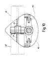
- Fig. 10
- eine Draufsicht von proximal nach distal auf eine Minilaparotomie mit bereits eingesetztem Nahthilfegerät in der Spreizstellung von Fig. 4,
- Fig. 11
- eine Seitenansicht einer Führungsschiene zum Einführen des Nahthilfegerätes in die Minilaparotomie,
- Fig. 12
- eine um 90° verdrehte Seitenansicht der Führungsschiene von Fig. 6 mit angesetztem Nahthilfegerät von Fig. 1,
- Fig. 13
- ein stark vergrößerter Querschnitt der Führungsnut der Führungsschiene von Fig. 11, wobei diese an einen Trokar angelegt ist,
- Fig. 14
- eine der Schnittdarstellung von Fig. 13 vergleichbare Schnittdarstellung mit angelegtem Nahthilfegerät,
- Fig. 15
- eine Seitenansicht eines weiteren Ausführungsbeispiels eines Nahthilfegerätes in Kunststoffversion,
- Fig. 16
- eine vergrößerte Darstellung des Nahthilfegerätes von Fig. 15 im distalen Bereich,
- Fig. 17
- einen Schnitt längs der Linie XVII-XVII in Fig. 16 und
- Fig. 18
- eine der Schnittdarstellung von Fig. 10 vergleichbare Darstellung des Nahthilfegerätes in seitlich ausgeklapptem Zustand.
- Fig. 1
- 2 shows a perspective view of a first exemplary embodiment of a seam aid device,
- Fig. 2
- 2 shows a partially schematic view of the distal end region of the suturing device in a proximally folded up working position of the support when it is pushed through a mini laparotomy,
- Fig. 3
- 2 shows a representation comparable to FIG. 2 in an intermediate position of the support that is already folded out to the side,
- Fig. 4
- 2 shows a representation comparable to the representations of FIGS. 2 and 3 in the laterally fully unfolded working position of the support,
- Fig. 5
- 2 shows a view comparable to the representations of FIGS. 2 to 4 with a working position of the support folded down distally during the pulling off from a mini laparotomy,
- Fig. 6
- 2 shows a perspective view from proximal to distal of the distal end region of the suturing device in a position corresponding to the position of FIG. 2,
- Fig. 7
- 3 shows a perspective representation corresponding to the representation of FIG. 3,
- Fig. 8
- 4 shows a perspective representation corresponding to the representation of FIG. 4,
- Fig. 9
- 5 shows a perspective representation corresponding to the representation of FIG. 5,
- Fig. 10
- 4 shows a plan view from proximal to distal of a mini laparotomy with the suturing aid already inserted in the spread position of FIG. 4,
- Fig. 11
- 2 shows a side view of a guide rail for inserting the suturing device into the mini laparotomy,
- Fig. 12
- 6 shows a side view of the guide rail from FIG. 6 rotated by 90 ° with the sewing aid device from FIG. 1 attached,
- Fig. 13
- 11 shows a greatly enlarged cross section of the guide groove of the guide rail from FIG. 11, this being applied to a trocar,
- Fig. 14
- 13 shows a sectional view comparable to the sectional view of FIG. 13 with the sewing aid device applied,
- Fig. 15
- 2 shows a side view of a further exemplary embodiment of a seam-aid device in a plastic version,
- Fig. 16
- 15 shows an enlarged illustration of the suture aid device of FIG. 15 in the distal area,
- Fig. 17
- a section along the line XVII-XVII in Fig. 16 and
- Fig. 18
- a comparable representation of the sectional view of FIG. 10 of the suture aid device in the laterally unfolded state.
Ein in Fig. 1 perspektivisch dargestelltes erstes Ausführungsbeispiel
eines Nahthilfegerätes ist in seiner Gesamtheit
mit der Bezugsziffer 10 versehen.A first exemplary embodiment shown in perspective in FIG. 1
of a suture aid device is in its entirety
provided with the
Das Nahthilfegerät 10 weist einen langerstreckten Schaft 12
in Form eines Rohres 14 auf.The
Am proximalen Ende des Rohres 14 ist ein Griff 16 vorgesehen,
der zwei sich diametral gegenüberstehende, etwa ringförmige,
sich in einer Ebene erstreckende Fingerösen 18, 18' aufweist.A
Am Griff 16 ist ein Feststellmechanismus 20 vorgesehen, der
einen Federhebel 22 aufweist.A
Der Federhebel 22 ist um eine am Griff 16 ortsfeste Schwenkachse
23 schwenkbar angebracht und weist an einem Ende einen
Zapfen 24 auf, der, wie später beschrieben wird, in entsprechende
Aussparungen bzw. Nuten sperrend eingreift.The
Der Federhebel 22 ist durch eine Feder 25 beaufschlagt, die
diesen in Feststell- bzw. Verriegelungsstellung drückt. An
dem dem Zapfen 24 gegenüberliegenden Ende ist der Federhebel
22 mit einer hier nicht näher bezeichneten Taste versehen,
die von einer Fingerkuppe betätigt werden kann.The
Im Rohr 14 des Schaftes 12 ist ein Betätigungselement 26 in
Form eines Stabes 28 längsverschieblich aufgenommen.In the
Der Stab 28 ist an seinem den Griff 16 proximal überragenden
Ende mit einer Fingeröse 30 versehen, die sich in derselben
Ebene wie die Fingerösen 18, 18' erstreckt.The
In dem in Fig. 1 ersichtlichen Abschnitt des Stabes 28 im Bereich
des Griffes 16 ist dieser mittig mit einer seitlichen
Abflachung 32 versehen, die einerseits dazu dient, daß der
Stab 28 verdrehsicher im Rohr 14 aufgenommen ist, wozu entsprechende
Klemmelemente vorgesehen sind.In the section of the
Die der in Fig. 1 ersichtlichen Abflachung 32 diametral
gegenüberliegenden Abflachung dient gleichzeitig als Gleitfläche
für den Zapfen 24 des Federhebels 22, wie das nachfolgend
noch näher in Zusammenhang mit der Funktionsweise beschrieben
wird.The flattening 32 shown in FIG. 1 is diametrical
opposite flattening also serves as a sliding surface
for the
Im Abstand zur Abflachung 32 ist proximal dazu eine erste
Ringnut 36 eingeschnitten, deren Flanken als Rampen 38 ausgebildet
sind. At a distance from the flat 32 there is a first proximal to it
Incised
An die relativ schmale Nut 36 schließt sich proximal eine relativ
breite Nut 40 an, deren Flanken ebenfalls als Rampen
ausgebildet sind.The relatively
Der Zapfen 24 ist so ausgebildet, daß er sowohl in die Nut 36
als auch in die breite Nut 40 einrasten kann.The
Am distalen Ende weist der Stab 28 ein abgewinkeltes Ende 42
auf, auf dem scharnierförmige Gelenke 44 einer Auflage 46
aufgenommen sind.At the distal end, the
Die Auflage 46 besteht aus zwei diametral gegenüberliegenden,
etwa rechteckförmigen Flügelplatten 48, 48', die somit
schwenkbar um das abgewinkelte Ende 42 des Stabes 28 montiert
sind. Die Mittellängsachse des abgewinkelten Endes 42 stellt
somit die Gelenkachse 45 bzw. die entsprechende Schwenkachse
der Flügelplatten 48, 48' dar. Auf der dem proximalen Ende
des Nahthilfegerätes 10 zugewandten Seite sind die Flügelplatten
48, 48' mittig mit einer sich längs der Längsachse
erstreckenden Führungsnut 49 bzw. 49' versehen.The
Die Flügelplatten 48, 48' sind über Betätigungshebel 50, 50'
gelenkig mit einem Flansch 51 am distalen Ende des Schaftes
12 verbunden. Der Betätigungshebel 50 ist, wie das insbesondere
auch in Zusammenhang mit Fig. 4 und 8 ersichtlich
ist, über einen Gelenkbolzen 52 einerseits gelenkig mit dem
Flansch 51 und andererseits über ein Gelenkbolzen 54 gelenkig
mit einer Seitenkante der Flügelplatte 48 verbunden. Der Abstand
zwischen Gelenkachse 45 und Gelenkbolzen 54 beträgt
etwa ein Drittel der axialen Länge der Flügelplatte 48. Entsprechendes
gilt dann für die gelenkige Verbindung der
Flügelplatte 48' mit dem Betätigungshebel 50'. The
Im Bereich des Griffs 16 ist am Schaft 12 ein radial vorspringender
Stutzen 56 vorgesehen, der zur Reinigung und zur
Spülung des hohlen Schaftes 12 dient.In the area of the
Die verschiedenen Arbeitspositionen und Schwenkstellungen der
Flügelplatten 48, 48' sollen nachfolgend anhand der Bildfolge
von Fig. 2 bis 5 beschrieben werden, wobei die Bildfolge von
Fig. 6 bis 9 entsprechende perspektivische Darstellungen der
Schwenkstellung der Flügelplatten 48, 48' zeigt.The different working positions and swivel positions of the
Die Grundstellung der Flügelplatten 48, 48', also so wie dem
Operateur das Nahthilfegerät 10 gereicht wird, ist die in
Fig. 1 bzw. in Fig. 8 dargestellte Stellung. In dieser Darstellung
sind die Flügelplatten 48, 48' etwa um 90° aus der
Schaftachse verschwenkt und erstrecken sich in ein und derselben
Ebene.The basic position of the
In dieser Stellung ist der Zapfen 24 des Feststellmechanismus
20 in die schmale Nut 36 des Stabes 28 eingerastet, somit
sind die Flügelplatten 48, 48' in dieser Schwenkstellung
unverrückbar.In this position, the
Der Operateur ergreift nunmehr das Nahthilfegerät 10, schiebt
zwei Finger in die Fingerösen 18, 18', bspw. den Zeigefinger
und Mittelfinger. Mit dem Daumen kann nun der Feststellmechanismus
20 gelöst werden, so daß das Nahthilfegerät 10
mit seinem distalen Ende voran in eine Minilaparotomie 112,
bspw. in einer Bauchdecke 110, eingeschoben werden kann, wie
das in Fig. 2 dargestellt ist. Die Fingeröse 30 braucht dazu
nicht ergriffen werden.The surgeon now grips the
Ein Vorgang zum Erleichtern dieses Einführens wird später in Zusammenhang mit den Fig. 11 bis 14 beschrieben. A process to facilitate this introduction is later in Described in connection with FIGS. 11 to 14.
Der Durchmesser der Minilaparotomie 112 ist wesentlich geringer
als die radiale Erstreckung der ausgeklappten Flügelplatten
48, 48', so daß diese nach proximal hochgeklappt werden
und dabei eine V-förmige Position einnehmen, wie sie in
Fig. 2 und 6 dargestellt ist. Dabei wird der Stab 28 gegen
die Kraft der Feder 34 im Schaft 12 nach distal verschoben,
die Fingeröse 30 bewegt sich also auf den Griff 16 zu. Dies
kann entweder vom Operateur unterstützt werden, dieser Vorgang
wird aber auch von den Wänden der Minilaparotomie 112
bewerkstelligt, ohne daß dadurch eine Verletzung oder eine
Aufweitung der Minilaparotomie 112 erfolgt. Der Operateur
kann also bspw. den Daumen aus der Fingeröse 30 bei diesem
Vorgang herausnehmen.The diameter of the
Wurde das distale, in der Zwischenzeit V-förmige Ende der
hochgeklappten Flügelplatten 48, 48' durch die Minilaparotomie
112 hindurchbewegt, wie das aus dem Übergang von Fig. 2
zu Fig. 3 ersichtlich ist, drückt die Kraft der Feder 34 den
Stab 28 im Schaft nach proximal. Über die Betätigungshebel
50, 50' werden die Flügelplatten 48, 48' seitlich ausgeschwenkt,
bis sie etwa die in Fig. 3 ersichtliche Zwischenposition
erreicht haben. In diesem Bereich ist der Zapfen 24
des Federhebels 22 des Feststellmechanismus 20 längs der
breiten Nut 40 gegleitet und ist nun an dessen distaler
Flanke, die als Rampe ausgebildet ist, angeschlagen.Was the distal, meanwhile V-shaped end of the
folded up
Der Übergang aus der Stellung von Fig. 2 zu Fig. 3 erfolgt
durch die Kraft der Feder 22 ruckartig, wobei dies mit einer
ruckartigen Bewegung der Fingeröse 30 verbunden ist, die der
Operateur erkennen kann, ihm also angezeigt ist, daß nunmehr
die Flügelplatten 48, 48' durch die Minilaparotomie 112 in
den freien Bauchraum durchgeschoben worden sind. The transition from the position from FIG. 2 to FIG. 3 takes place
jerky by the force of the
Nunmehr zieht der Operateur das Nahthilfegerät 10 etwas
zurück und legt dabei die Flügelplatten 48, 48' an der Unterseite
114 der Bauchdecke 110 an, wie das in Fig. 4 gezeigt
ist. Bei dem Übergang von der Schwenkstellung von Fig. 3 zu
Fig. 4 überläuft der Zapfen 24 die Flanke bzw. Rampe der Nut
40 und ist wieder in die Nut 36 eingerastet. Dem Operateur
zeigt sich die Minilaparotomie 112 von der Außenseite wie in
Fig. 10 dargestellt. Von der Außenseite her kann nunmehr ein
Haken mit einem Faden, bspw. ein Dechamps-Haken, dessen Ende
korkenzieherartig gedreht ist, eingeschoben werden und Nähte
bzw. ein Faden 116 gelegt werden, wie dies in Fig. 5 angedeutet
ist. Zur Erleichterung der Orientierung des Nahtwerkzeuges
dienen Führungsnuten 49, 49' auf den Flügelplatten 48,
48', die der Übersichtlichkeit halber nur in den Fig. 1 und
10 dargestellt sind. Man kann also den Dechamps-Haken, nachdem
er jeweils auf die Flügelplatte 48 bzw. die Flügelplatte
48' gestoßen ist, etwas verschieben, bis er in die Nut 49
bzw. 49' eintritt. Das Nahtwerkzeug ist nun ausrichtbar und
der Operateur kann beidseits des Schaftes den Faden 116 so
legen wie in Fig. 5 angedeutet.Now the surgeon pulls the
Nach Legen des Fadens 116 wird der Feststellmechanismus 20
erneut entriegelt und der Stab 28 wird über die Fingeröse 30,
in die der Daumen eingeschoben ist, nach proximal gezogen.After threading 116, the
Die Betätigungshebel 50, 50' drücken nunmehr die Flügelplatten
48, 48' in der Darstellung von Fig. 5 nach unten,
diese werden somit distal abgeklappt, und zwar in eine V-förmige
Stellung, wie sie in Fig. 5 dargestellt ist. Ein
weiteres Abklappen ist nicht notwendig und auch nicht
wünschenswert, so daß ausgeschlossen ist, daß zwischen die
abgeklappten Flügelplatten 48, 48' Gewebeteile eingeklemmt
werden können. The actuating levers 50, 50 'now press the
Der Zapfen 24 des Feststellmechanismus gleitet nunmehr längs
der Abflachung 32 des Stabes 28.The
In der in Fig. 5 dargestellten Stellung kann nunmehr problemlos
das Nahthilfegerät 10 von der Minilaparotomie 112 somit
vom Körper abgezogen werden.In the position shown in Fig. 5 can now easily
the
Anschließend kann der Faden 116 verknotet und somit die
Minilaparotomie verschlossen werden.The
Zum Erleichtern des Ansetzens und Einbringens des Nahthilfegerätes
10 in die Minilaparotomie 112 ist die in Fig. 11 ersichtliche
Führungsschiene 60 vorgesehen.To facilitate the attachment and insertion of the
Die Führungsschiene 60 weist eine Führungsnut 62 auf, an die
das Nahthilfegerät 10 wie in Fig. 12 dargestellt angesetzt
werden kann. Die Führungsschiene 60 weist einen abgewinkelten
Griff 64 auf, so daß beide Geräte, also Führungsschiene 60
und Nahthilfegerät 10 von unterschiedlichen Händen gehalten
werden können, ohne sich gegenseitig zu beeinträchtigen. In
der Führungsschiene 60 ist eine Skala 68 vorgesehen, über die
die Einschubtiefe abgelesen werden kann.The
Aus der vergrößerten Schnittdarstellung von Fig. 13 ist zu
erkennen, daß die Führungsnut 62 ein bestimmtes Querschnittsprofil
aufweist.From the enlarged sectional view of Fig. 13 is too
recognize that the
Dieses Querschnittsprofil ist so gestaltet, daß die Führungsschiene
16 längs eines Trokars, wie er in Fig. 13 durch die
Konturlinie 66 angedeutet ist, in den Körper eingeschoben
werden kann. This cross-sectional profile is designed so that the
Nach Einschieben der Führungsschiene 16, wobei die
Einschubtiefe über die Skala 68 kontrolliert werden kann,
wird der Trokar abgezogen. Anschließend wird das
Nahthilfegerät 10 an die Führungsnut 62 angesetzt, wie das in
Fig. 12 und 14 dargestellt ist und in den Körper ein- bzw.
durch die Minilaparotomie 112 durchgeschoben. Dieses
Zusatzgerät erleichtert die Handhabung, insbesondere das
atraumatische Ansetzen und Einführen des Nahthilfegerätes 10.After insertion of the
Das zuvor beschriebene Nahthilfegerät 10 ist vollständig aus
Metall hergestellt und somit als mehrfach verwendbares
Instrument ausgebildet, das autoklavierbar ist.The previously described
In den Fig. 15 bis 18 ist eine weitere Ausgestaltung eines
erfindungsgemäßen Nahthilfegerätes dargestellt, das in seiner
Gesamtheit mit der Bezugsziffer 70 versehen ist.15 to 18 is a further embodiment of a
Seam aid according to the invention shown that in its
Entire is provided with the
Das Nahthilfegerät 70 ist prinzipiell gleich wie das Nahthilfegerät
10 ausgebildet, jedoch vollständig aus Kunststoff,
insbesondere aus Kunststoffspritzteilen, hergestellt, somit
kostengünstiger herzustellen und ggf. als Einweggerät einzusetzen.The
Das Nahthilfegerät 70 weist dementsprechend einen Schaft 72
auf, der als Rohr 74 ausgebildet ist. Proximal ist das Rohr
74 mit einem Griff 76 versehen, der zwei Fingerösen 78, 78'
aufweist.The
Im Rohr 74 ist ein Betätigungselement 80 in Form eines längsverschieblichen
Stabes 82 aufgenommen, der proximal mit einer
Fingeröse 84 versehen ist. In the
Distal weist der Stab 82 ein abgewinkeltes Ende 86 auf (siehe
insbesondere Fig. 17), an dem seitlich über biegsame Kunststoffbrücken
88, 88' die Flügelplatten 89, 89' einstückig angespritzt
sind. Die biegsamen Kunststoffbrücken 88, 88'
bilden somit Filmscharniere. Zwei Betätigungshebel 90, 90'
sind über Kunststoffbrücken 92, 92' (siehe insbesondere Fig.
16) mit dem distalen Ende des Rohrs 74 gelenkig verbunden. Am
gegenüberliegenden Ende sind die Betätigungshebel 90, 90' auf
gelenkbolzenartige Fortsätze 94, 94' an den Seitenkanten der
Flügelplatten 89, 89' aufgeclipst.Distally, the
Wie insbesondere aus der Darstellung von Fig. 18 ersichtlich
ist, sind auf den Flügelplatten 89, 89' zwei längsverlaufende
Führungsnuten 96, 97 bzw. 96', 97' vorgesehen.As can be seen in particular from the illustration in FIG. 18
there are two longitudinal ends on the
An entsprechenden Stellen sind auch am abgewinkelten Ende 86
des Stabes 82 entsprechende Führungsnuten 98 und 99 vorgesehen,
so daß eine durchgehende Führung vorgesehen ist. Längs
der Außenseite des Stabes 82 ist ein Steg 100 in Form eines
Angusses angesetzt.At the appropriate locations there are also 86 at the angled end
corresponding
Das Rohr 74 weist eine entsprechende Innenkontur auf, wie das
aus der Schnittdarstellung von Fig. 18 ersichtlich ist, somit
ist der Stab 82 drehsicher im Rohr 94 aufgenommen.The
Am proximalen Ende, vor der Fingeröse 84, sind im Steg 100
Aussparungen 104, 105, 106 vorgesehen, in die eine entsprechende
Noppe 102 des Griffes 76 elastisch ein- bzw. ausrasten
kann, dazu sind die Aussparungen mit entsprechenden
Ein- bzw. Auslaufschrägen versehen. Die drei Aussparungen
104, 105, 106 zeigen bzw. entsprechen den drei Arbeitsstellungen,
dementsprechend ist die Noppe 102 in der Darstellung
von Fig. 15 in die mittlere Aussparung 105 eingerastet,
somit in der Arbeitsposition, in der die Flügelplatten
89, 89' etwa rechtwinklig seitlich ausgeschwenkt
sind. Da bei dieser Konstruktion keine Feder vorgesehen sein
muß, die den Stab beaufschlagt, werden die Flügelplatten 89,
89' über die Fingeröse 84 in die entsprechenden hochgeklappten
bzw. abgeklappten Stellungen bewegt, wobei dann entsprechend
die Noppe 102 in die Aussparung 104 bzw. 106 einrastet.At the proximal end, in front of the
Am distalen Endbereich des Stabes 82 ist ein radial
vorspringender Zapfen 108 vorgesehen, der in eine
entsprechende Nut in einer Führungsschiene eingesetzt werden
kann, um ein definiertes Einschieben des Nahthilfegerätes 70
zu erreichen.At the distal end region of the
Claims (17)
- Suturing aid for closing minilaparotomies (112) from minimal-invasive surgical operations, characterized by a shaft (12, 72) whose distal end is provided with at least one plane support (46), that can be swung out laterally, and an actuating element (26, 80) for swinging out the support (46), whereby the support (46) can be moved between a working position in which it is folded up toward the proximal end, a working position in which it is folded out laterally, and a working position in which it is folded down toward the distal end.
- Suturing aid according to claim 1, characterized in that said support (46) comprises two diametrically opposite vanes (48, 48'; 89, 89').
- Suturing aid according to claim 1 or Claim 2, characterized in that said actuating element (26, 80) is configured as a rod (28, 82), which is arranged to slide along said shaft (12, 72) and is hinged, on the distal end, on said support (46), with the axis (45) of the hinge forming the pivot axis of said support (46).
- Suturing aid according to one of claims 1 to 3, characterized in that said support (46) is hinged, at a certain distance from its pivot axis (45), on one end of an actuating lever (50, 50'; 90, 90') whose other end is hinged on said shaft (12, 72).
- Suturing aid according to claim 4, characterized in that the distance between said pivot axis (45) of said support (46) and the connection point of said lever (50, 50'; 90, 90') corresponds to approximately one third of the overall length of said support (46).
- Suturing aid according to anyone of claims 1 to 5, characterized in that at least one guide (49, 49'; 96, 96'; 97, 97') for a suturing tool is provided on the side of the support facing the proximal end of said suturing aid (10, 70).
- Suturing aid according to anyone of claims 1 to 6, characterized in that said actuating element (26, 80) is protected against torsion inside said shaft (12, 72).
- Suturing aid according to anyone of claims 1 to 7, characterized in that said actuating element (26) is biased by a spring (34) in such a way that said support (46) is moved automatically from its working position, in which it is folded up toward the proximal end, to its laterally folded-out working position.
- Suturing aid according to claim 8, characterized in that the spring force (34) is adjusted in such a way that said working support (46) will be folded out laterally only to an intermediate position somewhat before the working position in which the support is fully folded out laterally.
- Suturing aid according to anyone of claims 1 to 9, characterized in that orientation marks (104, 105, 106) are provided on said shaft (12, 72) and/or on said actuating element (26, 80) that indicate the angular position which the working support occupies at any time.
- Suturing aid according to anyone of claims 1 to 10, characterized in that a fixing mechanism (20) is provided by means of which said support (46) can be locked in given angular positions.
- Suturing aid according to claim 11, characterized in that said fixing mechanism (20) is configured as a spring lever (22), pivoted on said shaft (12, 72), which comprises a locking element (24, 102) arranged to engage corresponding recesses (36, 40; 104, 105, 106) provided on said actuating element (26, 80).
- Suturing aid according to claim 12, characterized in that said recesses (36, 40; 104, 105, 106) are provided with ramps (38) that provoke a noticeable snap-in effect.
- Suturing aid according to anyone of claims 1 to 13, characterized in that a special guide rail (60) is provided to assist the introduction of the suturing aid into the minilaparotomy.
- Suturing aid according to Claim 14, characterized in that said guide rail (60) comprises a bent-off handle (64).
- Suturing aid according to claim 14 or claim 15, characterized in that said guide rail comprises a guide groove for a guide pin (108) at the distal end of said actuating element, which permits the depth of penetration of the suturing aid, relative to the depth of penetration of the guide rail, to be guided and controlled in a detectable fashion.
- Suturing aid according to anyone of claims 14 to 16, characterized in that the guide rail is provided with a graduation (68).
Applications Claiming Priority (5)
| Application Number | Priority Date | Filing Date | Title |
|---|---|---|---|
| DE19618885 | 1996-05-10 | ||
| DE19618885 | 1996-05-10 | ||
| DE19635354A DE19635354A1 (en) | 1996-05-10 | 1996-08-31 | Suture aid device for minimally invasive surgical procedures |
| DE19635354 | 1996-08-31 | ||
| PCT/EP1997/002365 WO1997042880A1 (en) | 1996-05-10 | 1997-05-08 | Suturing aid |
Publications (2)
| Publication Number | Publication Date |
|---|---|
| EP0902649A1 EP0902649A1 (en) | 1999-03-24 |
| EP0902649B1 true EP0902649B1 (en) | 2001-09-05 |
Family
ID=26025591
Family Applications (1)
| Application Number | Title | Priority Date | Filing Date |
|---|---|---|---|
| EP97923027A Expired - Lifetime EP0902649B1 (en) | 1996-05-10 | 1997-05-08 | Suturing aid |
Country Status (4)
| Country | Link |
|---|---|
| US (1) | US6296648B1 (en) |
| EP (1) | EP0902649B1 (en) |
| JP (1) | JP3912620B2 (en) |
| WO (1) | WO1997042880A1 (en) |
Families Citing this family (19)
| Publication number | Priority date | Publication date | Assignee | Title |
|---|---|---|---|---|
| US6626914B2 (en) * | 1996-05-17 | 2003-09-30 | Jomed N.V. | Graft connector, an introducer therefor and a method of making a branch connection |
| US6814421B2 (en) * | 2002-10-24 | 2004-11-09 | Hewlett-Packard Development Company, L.P. | Printing device and method |
| EP1749479A1 (en) * | 2005-08-02 | 2007-02-07 | Marco Gandini | Retractor instrument |
| US20110082475A1 (en) * | 2009-10-01 | 2011-04-07 | Tyco Healthcare Group Lp | Wound closure device including ferrule ejector system |
| US8906042B2 (en) | 2010-07-29 | 2014-12-09 | Covidien Lp | Wound closure device including mesh barrier |
| US9327160B2 (en) | 2011-03-22 | 2016-05-03 | Jake Samuel Tauriainen | Modular self-spotting safety device for weightlifting |
| JP5963559B2 (en) | 2012-06-18 | 2016-08-03 | 日本コヴィディエン株式会社 | Medical suture tool |
| US10426472B2 (en) | 2013-08-02 | 2019-10-01 | Covidien Lp | Devices, systems, and methods for wound closure |
| US10070851B2 (en) | 2013-08-02 | 2018-09-11 | Covidien Lp | Devices, systems, and methods for wound closure |
| JP6393142B2 (en) * | 2014-10-02 | 2018-09-19 | 株式会社九研 | Surgical surgeons |
| CN106308883A (en) * | 2015-06-30 | 2017-01-11 | 李楠 | Inferior vena cava root blood vessel anatomic separating forceps applied to laparotomy |
| CN106551709A (en) * | 2015-09-30 | 2017-04-05 | 爱微捷成都医疗科技有限公司 | Abdomen wall sewing device |
| US10188381B2 (en) | 2015-11-20 | 2019-01-29 | Dura Tap Llc | Suture repair device |
| CN108289659B (en) | 2015-11-25 | 2022-06-28 | 爪医疗有限公司 | Tissue engaging devices, systems and methods |
| CN107625539B (en) * | 2017-10-12 | 2020-04-17 | 高密市卫生学校 | Oral cavity expander |
| US11213288B2 (en) | 2018-05-02 | 2022-01-04 | Covidien Lp | Port site closure instrument |
| US11234690B2 (en) | 2018-05-02 | 2022-02-01 | Covidien Lp | Method and device for closing a port site incision |
| CN111096769B (en) * | 2019-12-31 | 2024-12-10 | 清华大学 | Auxiliary suturing device for hollow organs |
| CN111588485B (en) * | 2020-06-04 | 2021-11-09 | 王冬 | Auxiliary instrument for small incision suturing of pleuroperitoneal cavity |
Family Cites Families (13)
| Publication number | Priority date | Publication date | Assignee | Title |
|---|---|---|---|---|
| DE640126C (en) * | 1934-07-29 | 1936-12-24 | Bruno Loewel Dr | Trocar |
| US4836205A (en) | 1988-03-21 | 1989-06-06 | Barrett Gene R | Grasper-stitcher device for arthroscopic anterior cruciate ligament repair |
| DE4021153A1 (en) | 1990-07-03 | 1992-01-16 | Wolf Gmbh Richard | ORGAN MANIPULATOR |
| US5176128A (en) | 1991-01-24 | 1993-01-05 | Andrese Craig A | Organ retractor |
| DE4210724C1 (en) | 1992-04-01 | 1993-07-22 | Rema-Medizintechnik Gmbh, 7201 Duerbheim, De | Surgical instrument with expander in shaft portion - has expanding member mounting eccentrical on pinion meshing with central gear on shaft passing through stem |
| US5351679A (en) | 1992-08-17 | 1994-10-04 | Ilya Mayzels | Surgical endoscopic retractor instrument |
| US5364408A (en) * | 1992-09-04 | 1994-11-15 | Laurus Medical Corporation | Endoscopic suture system |
| US5507755A (en) * | 1993-08-03 | 1996-04-16 | Origin Medsystems, Inc. | Apparatus and method for closing puncture wounds |
| US5391182A (en) * | 1993-08-03 | 1995-02-21 | Origin Medsystems, Inc. | Apparatus and method for closing puncture wounds |
| US5474568A (en) | 1993-10-08 | 1995-12-12 | United States Surgical Corporation | Instrument for closing trocar puncture wounds |
| DE4415521C2 (en) | 1994-05-04 | 2003-01-30 | Storz Reling Sybill Gesamthand | Instrument for use in endoscopic procedures |
| US5573495A (en) * | 1994-08-19 | 1996-11-12 | Flexbar Machine Corp. | Abdominal wall elevator device employing rotatable arms |
| DE19635354A1 (en) | 1996-05-10 | 1997-11-20 | Storz Karl Gmbh & Co | Suture aid device for minimally invasive surgical procedures |
-
1997
- 1997-05-08 US US09/180,634 patent/US6296648B1/en not_active Expired - Fee Related
- 1997-05-08 WO PCT/EP1997/002365 patent/WO1997042880A1/en not_active Ceased
- 1997-05-08 EP EP97923027A patent/EP0902649B1/en not_active Expired - Lifetime
- 1997-05-08 JP JP54049197A patent/JP3912620B2/en not_active Expired - Fee Related
Also Published As
| Publication number | Publication date |
|---|---|
| JP3912620B2 (en) | 2007-05-09 |
| WO1997042880A1 (en) | 1997-11-20 |
| EP0902649A1 (en) | 1999-03-24 |
| US6296648B1 (en) | 2001-10-02 |
| JP2000510015A (en) | 2000-08-08 |
Similar Documents
| Publication | Publication Date | Title |
|---|---|---|
| EP0902649B1 (en) | Suturing aid | |
| DE69622969T2 (en) | WOUND CLOSURE DEVICE | |
| DE69309509T2 (en) | Endoscopic surgery facility | |
| DE69632547T2 (en) | trocar | |
| DE60225619T2 (en) | Subcutaneous suturing device for closing an opening of the abdominal wall of a patient | |
| DE69416477T2 (en) | Sheet-shaped surgical material applicator | |
| DE69930104T2 (en) | ENDOSCOPIC SEWING SYSTEM | |
| DE69735501T2 (en) | SYSTEMS AND INSTRUMENTS FOR MINIMALLY INVASIVE SURGERY | |
| DE60304007T2 (en) | Surgical clamp and fixation device for it | |
| DE19848958B4 (en) | Device for manipulating sutures during endoscopic surgical procedures | |
| DE69314140T2 (en) | Endoscopic surgical instrument | |
| DE69314255T2 (en) | Device for deploying a surgical element | |
| DE19906260C2 (en) | Dissection retractor for vascular removal | |
| DE4306277C2 (en) | Operation marking tool | |
| DE69636839T2 (en) | END-OF-SURGICAL INSTRUMENT WITH A RADIAL MOVABLE HANDLE | |
| EP0742695B1 (en) | Microsurgery instrument | |
| DE102012221109B4 (en) | Surgical instrument and handle for a surgical instrument | |
| EP0684012A2 (en) | Thread for applying a surgical suture, transfer holder and surgical suturing instrument | |
| DE29909688U1 (en) | Surgical ligation instrument | |
| DE9290082U1 (en) | Instrument walker | |
| EP1083834B1 (en) | Device for producing a transcutaneous access to a hollow viscus in the interior of the body | |
| WO1999049794A1 (en) | Surgical instrument with a continuous hollow channel for another instrument | |
| EP1601293B1 (en) | Medical equipment for creating a surgical space for oral surgery | |
| WO2014067840A1 (en) | Atrium retractor | |
| EP2361040B1 (en) | Instrument for laparoscopic surgery |
Legal Events
| Date | Code | Title | Description |
|---|---|---|---|
| PUAI | Public reference made under article 153(3) epc to a published international application that has entered the european phase |
Free format text: ORIGINAL CODE: 0009012 |
|
| 17P | Request for examination filed |
Effective date: 19981125 |
|
| AK | Designated contracting states |
Kind code of ref document: A1 Designated state(s): DE FR GB IT |
|
| RAP1 | Party data changed (applicant data changed or rights of an application transferred) |
Owner name: KARL STORZ GMBH & CO. KG |
|
| GRAG | Despatch of communication of intention to grant |
Free format text: ORIGINAL CODE: EPIDOS AGRA |
|
| GRAG | Despatch of communication of intention to grant |
Free format text: ORIGINAL CODE: EPIDOS AGRA |
|
| GRAH | Despatch of communication of intention to grant a patent |
Free format text: ORIGINAL CODE: EPIDOS IGRA |
|
| 17Q | First examination report despatched |
Effective date: 20001103 |
|
| GRAH | Despatch of communication of intention to grant a patent |
Free format text: ORIGINAL CODE: EPIDOS IGRA |
|
| GRAA | (expected) grant |
Free format text: ORIGINAL CODE: 0009210 |
|
| AK | Designated contracting states |
Kind code of ref document: B1 Designated state(s): DE FR GB IT |
|
| REF | Corresponds to: |
Ref document number: 59704540 Country of ref document: DE Date of ref document: 20011011 |
|
| REG | Reference to a national code |
Ref country code: GB Ref legal event code: IF02 |
|
| GBT | Gb: translation of ep patent filed (gb section 77(6)(a)/1977) |
Effective date: 20011212 |
|
| ET | Fr: translation filed | ||
| PLBE | No opposition filed within time limit |
Free format text: ORIGINAL CODE: 0009261 |
|
| STAA | Information on the status of an ep patent application or granted ep patent |
Free format text: STATUS: NO OPPOSITION FILED WITHIN TIME LIMIT |
|
| 26N | No opposition filed | ||
| PGFP | Annual fee paid to national office [announced via postgrant information from national office to epo] |
Ref country code: GB Payment date: 20120423 Year of fee payment: 16 Ref country code: FR Payment date: 20120625 Year of fee payment: 16 |
|
| PGFP | Annual fee paid to national office [announced via postgrant information from national office to epo] |
Ref country code: IT Payment date: 20120421 Year of fee payment: 16 |
|
| GBPC | Gb: european patent ceased through non-payment of renewal fee |
Effective date: 20130508 |
|
| PG25 | Lapsed in a contracting state [announced via postgrant information from national office to epo] |
Ref country code: IT Free format text: LAPSE BECAUSE OF NON-PAYMENT OF DUE FEES Effective date: 20130508 |
|
| REG | Reference to a national code |
Ref country code: FR Ref legal event code: ST Effective date: 20140131 |
|
| PG25 | Lapsed in a contracting state [announced via postgrant information from national office to epo] |
Ref country code: GB Free format text: LAPSE BECAUSE OF NON-PAYMENT OF DUE FEES Effective date: 20130508 |
|
| PG25 | Lapsed in a contracting state [announced via postgrant information from national office to epo] |
Ref country code: FR Free format text: LAPSE BECAUSE OF NON-PAYMENT OF DUE FEES Effective date: 20130531 |
|
| PGFP | Annual fee paid to national office [announced via postgrant information from national office to epo] |
Ref country code: DE Payment date: 20140424 Year of fee payment: 18 |
|
| REG | Reference to a national code |
Ref country code: DE Ref legal event code: R119 Ref document number: 59704540 Country of ref document: DE |
|
| PG25 | Lapsed in a contracting state [announced via postgrant information from national office to epo] |
Ref country code: DE Free format text: LAPSE BECAUSE OF NON-PAYMENT OF DUE FEES Effective date: 20151201 |