EP0901838A1 - Racleur pour la surface de collection de l'excédent pulvérisé d'une installation de revêtement par pulvérisation - Google Patents
Racleur pour la surface de collection de l'excédent pulvérisé d'une installation de revêtement par pulvérisation Download PDFInfo
- Publication number
- EP0901838A1 EP0901838A1 EP98116926A EP98116926A EP0901838A1 EP 0901838 A1 EP0901838 A1 EP 0901838A1 EP 98116926 A EP98116926 A EP 98116926A EP 98116926 A EP98116926 A EP 98116926A EP 0901838 A1 EP0901838 A1 EP 0901838A1
- Authority
- EP
- European Patent Office
- Prior art keywords
- precipitation
- holder
- spar
- scraper
- area
- Prior art date
- Legal status (The legal status is an assumption and is not a legal conclusion. Google has not performed a legal analysis and makes no representation as to the accuracy of the status listed.)
- Withdrawn
Links
Images

Classifications
-
- B—PERFORMING OPERATIONS; TRANSPORTING
- B05—SPRAYING OR ATOMISING IN GENERAL; APPLYING FLUENT MATERIALS TO SURFACES, IN GENERAL
- B05B—SPRAYING APPARATUS; ATOMISING APPARATUS; NOZZLES
- B05B14/00—Arrangements for collecting, re-using or eliminating excess spraying material
- B05B14/40—Arrangements for collecting, re-using or eliminating excess spraying material for use in spray booths
- B05B14/41—Arrangements for collecting, re-using or eliminating excess spraying material for use in spray booths by cleaning the walls of the booth
Definitions
- the invention relates to a device for systems for spraying and Spray coating objects with at least one essentially upright precipitation area for what passes past the objects Spray or spray medium and at least one over the precipitation area movable scraper for stripping the precipitation from the precipitation surface and a drip pan located below the precipitation area, the scraper spreads across the precipitation area extending spar has at least one wiper lip and this spar at both ends with one arranged to the side of the precipitation surface Guide and / or drive device is connected.
- Comparable devices of this type are in various embodiments became known: DE 28 23 958 A1; DE 29 30 080 A1; DE 31 47 809 A1; DE 32 02 481 A1; DE 43 38 450 A1; DE 93 20 654 U1; GB 2 227 991 A.
- the device of this type according to EP 065 656 B1 should be mentioned in particular here.
- the one provided here which extends across the width of the precipitation area
- the scraper is connected at the end with circumferential chains that are on the side of Rain area are arranged.
- the scraper is turned around by this chain the precipitation area led around, the existing consisting of holder and sealing lip Scraper represents a uniform, rigid structure.
- This stripper is spaced along using the carrying and conveyor chains of the precipitation area led downwards, with that on the precipitation area the excess wiping lip adhering to this surface Spray or spray pushes down, which then on the lower Edge of the precipitation area falls into a collecting trough underneath, from where it is removed in a known manner.
- the chain drives that over Deflection rollers are guided, then guide the scraper on the back of the precipitation area back up to the starting position.
- the present invention represents an immediate further development of this known device and aims to train the scraper so that the precipitation surface can be optimally cleaned with its help.
- the invention is characterized in that on the spar at least one by one Swiveling holder parallel to the longitudinal axis of the spar is provided, on the lower edge of the wiper lip positive and / or non-positive is held.
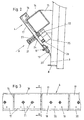
- a precipitation surface 3 suspended and slidable along this guide.
- This rainfall area 3 has an essentially known structure.
- electrically conductive wires can be integrated to cover the precipitation surface over these wires 3 to apply to an electrostatic potential, which is known per se is.
- On the lower edge of the precipitation surface 3 is an elastic scraper 8 arranged opposite this precipitation surface 3 to the front protrudes.
- This elastic squeegee 8 can on the lower edge of the precipitation surface 3 be arranged fixed. But it is also possible to do this Scraper 8 adjustable to store: The adjustment range is chosen so that the squeegee 8, as shown in FIG. 2, opposite the precipitation surface 3 protrudes or is completely set back with respect to this, so that its front edge flush with the level of the precipitation surface 3 or even behind it lies.
- a scraper 4 is arranged in front of this precipitation surface 3, which in FIG its two end positions is shown, with its upper starting position with full lines are reproduced, but its lower end position with dashed lines.
- This scraper 4 is at the front of the precipitation area up and down (arrow 5).
- the Precipitation area 3 threaded spindles, not shown here, provided in the level of this precipitation area and parallel to the lateral Border edges of the rectangularly shaped precipitation area run. Conveniently these two threaded spindles can be driven independently of one another.
- the ends of the scraper 4 are fitted with nuts on them Lead screws run. These nuts are hinged to the ends of the Scraper 4 connected, the axes of these hinges are at right angles to the level of the precipitation surface 3.
- other management and drive elements can also be provided.
- Below a collecting trough 6 is arranged on the underside of the precipitation surface 3.
- a spray device 7 Fixed on the guide device 2 and parallel to the precipitation area 3, a spray device 7 is provided. This consists of a pipe with outlet nozzles. The tube can be rotated around its longitudinal axis to change the spray direction of the outlet nozzles relative to the precipitation surface 3. The central pipe of this spray device is connected to a water supply connected.
- Air channels 9 are provided in the ceiling area of room 1. Below the Exhaust air ducts 11 are arranged in the rust-like bottom 10. On one ceiling arranged guide rail 12 are the workpieces 13 to be coated hung and are by means of this guide rail 12 to the precipitation surface 3 approached and led away from this.
- the scraper 4 is in FIGS. 2 and 3 in detail and in one with respect to these Figures shown enlarged scale.
- This stripper 4 consists of a Spar 14, which extends across the width of the precipitation area.
- the end arranged boom 15 are arranged with the side of the precipitation surface 3 and drivable and above-mentioned threaded spindles.
- On this spar 14 are a number of juxtaposed over a pivot axis 16 Holder 17 arranged. 3, which shows a view of this arrangement, the individual in the row of successive holders are somewhat apart distanced, for the sake of illustration.
- these holders are close together or the wiper lips 20 are designed so that the successive in the row Touch the wiper lips.
- FIG. 2 illustrates the position of the wiper lip 20 when the wiper 4 along the precipitation surface 3 is driven from the top to the bottom to the depressed To strip off spray or spray material.
- the wiper lip pushes the excess material in front of it and the scraper 4 becomes as far behind moved down until the wiper lip is the elastically deformable, opposite the precipitation surface 3 protruding squeegee 8 on the lower edge of the precipitation area 3 has run over.
- the excess material stripped off falls into the sump 6, from where it can be reused in the usual way is forwarded.
- the squeegee 8 is mounted so that it is opposite the precipitation surface 3 can be reset by a suitable program control causes the squeegee when moving down the wiper lip 20 is set back so that the excess material that is in the Rain area 3 is located, can more easily run down or fall off. Before the wiper lip 20 returns to its upper starting position introduced by the program control mentioned the squeegee, so that it cleans the back of the wiper lip 20 when it is raised.
- the elasticity of the Squeegee 8 can be in a wide range, it can be deformed relatively easily or be relatively stiff.
- the scraper 4 can if the serving as guide and drive elements laterally arranged threaded spindles are driven synchronously, in horizontal Can be moved downwards or upwards. It is also possible to drive the threaded spindles at different speeds or switch on the drives with a time delay. In this case, the Scraper at an angle to the precipitation surface 3. Thanks to the hinge-like connection between the nuts running on the threaded rods and the ends of the spar 14 this inclination is possible.
- the precipitation surface 3 will be arranged close to the wall, like this 1 can be seen. So that the precipitation area is also accessible from behind it is horizontally displaceable on the guide device 2 mentioned at the beginning stored so that it can be moved away from the wall and is then accessible from behind.
- the precipitation surface 3 can be made of a suitable plastic or consist of a plastic-coated metal plate. To the viscosity of the To maintain coating material, the precipitation area 3 is about the spray device 7 sprayed with water. An additional or different possibility to moisten the precipitation area 3 consists in the precipitation area To integrate 3 pipes, which are flowed through by a cool medium become. The resulting cooling of the precipitation surface caused condensation due to the usually existing air humidity this precipitation area 3.
- the adjusting screw 21 passes through Coil springs 23 and 24. These coil springs or at least one of them can also be replaced by a rubber-elastic sleeve.
- the embodiment is the spar 14 through a box profile with a square Cross section formed. Other cross-sectional shapes can also be used for this spar be used.
- the guide and drive device for the scraper 4 is in the drawings not shown, but their constructive structure results from the above Description.
- the pivotable holder for the wiper lip 20 and the longitudinal division of this wiper lip ensures optimal cleaning the precipitation area 3 achieved.
Landscapes
- Spray Control Apparatus (AREA)
Applications Claiming Priority (2)
| Application Number | Priority Date | Filing Date | Title |
|---|---|---|---|
| AT1532/97 | 1997-09-11 | ||
| AT153297 | 1997-09-11 |
Publications (1)
| Publication Number | Publication Date |
|---|---|
| EP0901838A1 true EP0901838A1 (fr) | 1999-03-17 |
Family
ID=3515555
Family Applications (1)
| Application Number | Title | Priority Date | Filing Date |
|---|---|---|---|
| EP98116926A Withdrawn EP0901838A1 (fr) | 1997-09-11 | 1998-09-08 | Racleur pour la surface de collection de l'excédent pulvérisé d'une installation de revêtement par pulvérisation |
Country Status (1)
| Country | Link |
|---|---|
| EP (1) | EP0901838A1 (fr) |
Cited By (1)
| Publication number | Priority date | Publication date | Assignee | Title |
|---|---|---|---|---|
| AT14720U1 (de) * | 2013-07-26 | 2016-04-15 | Schuko Heinz Schulte Südhoff Gmbh & Co Kg | Farbnebelabsaugwand und Lackieranlage |
Citations (5)
| Publication number | Priority date | Publication date | Assignee | Title |
|---|---|---|---|---|
| EP0065656A2 (fr) * | 1981-05-23 | 1982-12-01 | Fritz Schäfer Gesellschaft mit beschränkter Haftung | Appareil pour le traitement à pulvérisation, particulièrement pour la pulvérisation de peinture |
| GB2125357A (en) * | 1982-08-06 | 1984-03-07 | Neville Reuben Thomas Stockton | Conveyor belt scraper mounting |
| EP0377071A1 (fr) * | 1988-12-23 | 1990-07-11 | Müller GmbH Herne | Racleur pour bandes transporteuses |
| DE9419181U1 (de) * | 1994-11-30 | 1995-01-26 | Hymmen Theodor Gmbh | Abstreifvorrichtung für endlose, um Umlenkwalzen geführte Bänder |
| WO1997014635A1 (fr) * | 1995-10-13 | 1997-04-24 | Ghislain Justin Marie Mat | Racloirs pour bande transporteuse |
-
1998
- 1998-09-08 EP EP98116926A patent/EP0901838A1/fr not_active Withdrawn
Patent Citations (5)
| Publication number | Priority date | Publication date | Assignee | Title |
|---|---|---|---|---|
| EP0065656A2 (fr) * | 1981-05-23 | 1982-12-01 | Fritz Schäfer Gesellschaft mit beschränkter Haftung | Appareil pour le traitement à pulvérisation, particulièrement pour la pulvérisation de peinture |
| GB2125357A (en) * | 1982-08-06 | 1984-03-07 | Neville Reuben Thomas Stockton | Conveyor belt scraper mounting |
| EP0377071A1 (fr) * | 1988-12-23 | 1990-07-11 | Müller GmbH Herne | Racleur pour bandes transporteuses |
| DE9419181U1 (de) * | 1994-11-30 | 1995-01-26 | Hymmen Theodor Gmbh | Abstreifvorrichtung für endlose, um Umlenkwalzen geführte Bänder |
| WO1997014635A1 (fr) * | 1995-10-13 | 1997-04-24 | Ghislain Justin Marie Mat | Racloirs pour bande transporteuse |
Cited By (1)
| Publication number | Priority date | Publication date | Assignee | Title |
|---|---|---|---|---|
| AT14720U1 (de) * | 2013-07-26 | 2016-04-15 | Schuko Heinz Schulte Südhoff Gmbh & Co Kg | Farbnebelabsaugwand und Lackieranlage |
Similar Documents
| Publication | Publication Date | Title |
|---|---|---|
| DE19718773B4 (de) | Lackierkopf | |
| EP0065656B1 (fr) | Appareil pour le traitement à pulvérisation, particulièrement pour la pulvérisation de peinture | |
| EP2476512A1 (fr) | Dispositif de soufflage pour bandes | |
| DE3135581C2 (fr) | ||
| DE3246574C2 (de) | Vorrichtung zur elektrostatischen Spritzlackierung | |
| EP0901838A1 (fr) | Racleur pour la surface de collection de l'excédent pulvérisé d'une installation de revêtement par pulvérisation | |
| DE3210679A1 (de) | Automatisches elektrostatisches zentrifugalzerstaeubersystem | |
| DE60306362T2 (de) | Düsen für eine reinigungsanlage einer druckmaschine | |
| EP0623393A1 (fr) | Installation de projection de peinture | |
| EP2738310B1 (fr) | Procédé et dispositif de production de marquages à partir de matériaux de marquage haute viscosité sur une surface de marquage | |
| DE3712474C2 (fr) | ||
| DE4103171C1 (fr) | ||
| DE3150946A1 (de) | "vorrichtung zum entzundern eines stahlstrangs" | |
| EP1818450B1 (fr) | Dispositif de revêtement par rideau | |
| EP3613643B1 (fr) | Installation de lavage de véhicules | |
| DE102009032907B3 (de) | Vorrichtung zum Entfernen von Rückständen von der Oberfläche eines bewegten Bandes sowie Bandbearbeitungsanlage | |
| DE4409269C2 (de) | Sprühbeschichtungsanlage | |
| DE2140383B2 (de) | Vorrichtung zur Änderung der Luftströme zum Abstreifen von Überzugsmaterial auf einem sich aufwärts bewegenden Streifen | |
| DE2145131B2 (de) | Vorrichtung zum gleichmäßigen und stufenlos veränderbaren Einölen von kontinuierlich bewegtem Walzgut, insbesondere von Blechbändern oder -tafeln | |
| DE3024130A1 (de) | Langgestreckte spruehkabine zum pulverbeschichten von werkstuecken | |
| DE19726078A1 (de) | Maschine zum Lackieren oder Einfärben von Werkstücken | |
| DE19744546A1 (de) | Vorrichtung zur Herstellung von flächigem Glas | |
| DE102017009877B4 (de) | Umlaufender Dichtungsvorhang zur Ölnebelabscheidung | |
| DE19511900C2 (de) | Vorrichtung zum Elektro-Tauchlackieren | |
| DE1949039C3 (de) | Vorrichtung zum Anstreichen von Brettern |
Legal Events
| Date | Code | Title | Description |
|---|---|---|---|
| PUAI | Public reference made under article 153(3) epc to a published international application that has entered the european phase |
Free format text: ORIGINAL CODE: 0009012 |
|
| AK | Designated contracting states |
Kind code of ref document: A1 Designated state(s): AT CH DE FR IT LI NL |
|
| AX | Request for extension of the european patent |
Free format text: AL;LT;LV;MK;RO;SI |
|
| 17P | Request for examination filed |
Effective date: 19990826 |
|
| AKX | Designation fees paid |
Free format text: AT CH DE FR IT LI NL |
|
| STAA | Information on the status of an ep patent application or granted ep patent |
Free format text: STATUS: THE APPLICATION IS DEEMED TO BE WITHDRAWN |
|
| 18D | Application deemed to be withdrawn |
Effective date: 20020403 |