EP0901774A1 - Appareil pour aider à la parturition des bestiaux - Google Patents
Appareil pour aider à la parturition des bestiaux Download PDFInfo
- Publication number
- EP0901774A1 EP0901774A1 EP98112114A EP98112114A EP0901774A1 EP 0901774 A1 EP0901774 A1 EP 0901774A1 EP 98112114 A EP98112114 A EP 98112114A EP 98112114 A EP98112114 A EP 98112114A EP 0901774 A1 EP0901774 A1 EP 0901774A1
- Authority
- EP
- European Patent Office
- Prior art keywords
- sleeve
- lever
- shaped part
- clamping
- clamping ring
- Prior art date
- Legal status (The legal status is an assumption and is not a legal conclusion. Google has not performed a legal analysis and makes no representation as to the accuracy of the status listed.)
- Granted
Links
- 241001465754 Metazoa Species 0.000 title claims description 14
- 230000032696 parturition Effects 0.000 title 1
- 241000283690 Bos taurus Species 0.000 claims abstract description 10
- 244000309466 calf Species 0.000 abstract 1
- 210000002414 leg Anatomy 0.000 description 29
- 230000015572 biosynthetic process Effects 0.000 description 1
- 230000000903 blocking effect Effects 0.000 description 1
- 230000006835 compression Effects 0.000 description 1
- 238000007906 compression Methods 0.000 description 1
- 238000011109 contamination Methods 0.000 description 1
- 230000001419 dependent effect Effects 0.000 description 1
- 230000000881 depressing effect Effects 0.000 description 1
- 230000000994 depressogenic effect Effects 0.000 description 1
- 230000000694 effects Effects 0.000 description 1
- 230000008774 maternal effect Effects 0.000 description 1
- 210000000689 upper leg Anatomy 0.000 description 1
Images

Classifications
-
- A—HUMAN NECESSITIES
- A61—MEDICAL OR VETERINARY SCIENCE; HYGIENE
- A61D—VETERINARY INSTRUMENTS, IMPLEMENTS, TOOLS, OR METHODS
- A61D1/00—Surgical instruments for veterinary use
- A61D1/08—Veterinary obstetrical instruments or devices
Definitions
- the invention relates to a device for cattle obstetrics, with a neck support that can be supported against the body of a mother animal, which picks up a pole with two arranged on the pole, alternately displaceable and lockable sleeve-shaped Split, with each sleeve-shaped part one off the bar enforced clamping ring, which means spring force in the sense one defining the sleeve-shaped part and the rod Is clamped, with at least two holding devices, on at least one of the two sleeve-shaped Parts are attached and in the direction of tension with the holding devices connectable leg slings for the Allow young animals, as well as in one of the sleeve-shaped parts a clamping lever is pivotally mounted at a distance from an intermediate link pivotally receives its pivot axis and the intermediate link also in the other sleeve-shaped part is pivotally mounted, with a device for releasing the fixed sleeve-shaped parts, one in one of the sleeve-
- Such a device for cattle obstetrics is from DE 44 41 795 C1 known.
- the clamping ring prevents the one sleeve-shaped Part in its clamping position that the clamping lever in its fully swiveled-in position can be transferred, because the approach of the clamping lever the end face of this clamping ring contacted.
- one sleeve-shaped part is one by hand plunger that can be actuated against spring force, the end face in contact with the clamping ring of a sleeve-shaped Part can be brought and this from its clamped position moves, the clamping ring also from the path of movement of the Approach lever attached approach so that this in his fully pivoted position can be transferred and so that the other approach of the pivot lever also take effect can of the clamping ring of the other sleeve-shaped part moved to its clamped position. So that the two are sleeve-shaped Parts released with respect to the rod and can be moved in the direction of Neck support or the mother animal slip, so that the tension the leg loops for the young animal are reduced.
- the trigger element designed as a plunger be operated in the immediate vicinity of the tensioning lever.
- the formation of the trigger element as a plunger also makes it required to exert significant triggering forces when the in the holding devices are attached to the leg slings.
- the device has a sleeve-shaped one Part assigned clamping ring the function of the stop for the Approach on the tension lever. For example, as a result of Contamination the provision of this clamping disc under Spring force is not perfect, so is the stop function this clamping ring for the attachment to the clamping lever is not guaranteed.
- EP 0 608 790 A1 describes a device for cattle obstetrics known in which a device for solving the two set sleeve-shaped parts is provided as a trigger element a pivotally mounted in a sleeve-shaped part Has release lever.
- a device for solving the two set sleeve-shaped parts is provided as a trigger element a pivotally mounted in a sleeve-shaped part Has release lever.
- the task is solved with a device for cattle obstetrics type mentioned in that the trigger element as Trigger lever pivotally mounted in a sleeve-shaped part is formed, the trigger lever having a shoulder, the in a first position of the release lever in the swivel path one end of the tension lever protrudes and a complete one Swiveling of the tensioning lever prevented, as well as the release lever when transferring to a second position in which he has the clamping ring one of the sleeve-shaped parts moved out of the clamping position, from the swivel path of the approach of the tensioning lever to it is completely swung in.
- the trigger element as Trigger lever pivotally mounted in a sleeve-shaped part is formed, the trigger lever having a shoulder, the in a first position of the release lever in the swivel path one end of the tension lever protrudes and a complete one Swiveling of the tensioning lever prevented, as well as the release lever when transferring to a second position in which
- the Approach of the release lever in its inactive position Block the tension lever by the approach of the release lever protrudes into the swivel path of the approach of the tensioning lever. Of the Clamping lever or its approach therefore contacts with this Condition of the clamping ring is not.
- the limitation of the swivel path the clamping lever depends only on the position of the release element or its approach. The clamping is released the clamping ring assigned to the trigger element immediately through the release element.
- the approach of the trigger element is pivoted out of the path of movement of the clamping lever, with what this now when moving the released sleeve-shaped Part fully swiveled on the rod and this the other approach of the tensioning lever the other's clamping ring sleeve-shaped part transferred to the unclamped position.
- the triggering element is not actuated in one rectilinear movement, but by means of a swivel movement.
- a special design provides that the release lever as Angle lever is formed, the trigger lever in the angular range its leg pivotable in the tension lever facing Area of a sleeve-shaped part is mounted.
- the leg that serves to contact the clamping ring in stored in its immediate vicinity, essentially parallel to this.
- the approach of the release lever is preferred in the area the pivot axis of the release lever.
- each Leg part is arranged on the side of the rod.
- the forces can be symmetrical to the central longitudinal axis of the rod to release the clamping of the clamping ring in the sleeve-shaped Part, which has the trigger element, are applied.
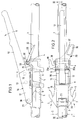
- FIGS. 1 and 2 points the device shown for the areas essential to the invention for cattle obstetrics a hollow tube designed as smooth on the outside Bar 1 on.
- the dash-dotted line 2 illustrates the Position of a not shown, against the body of the Maternal supportable neck support, in which the rod with one end is insertable. The end facing away from the mother animal the rod is also not clearly illustrated and is useful a handle on. Between the neck support and the with the other end of the rod connected handle are on the Rod 1 two alternately slidable and lockable, sleeve-shaped parts 3 and 4 arranged.
- the mother animal facing sleeve-shaped part 3 is arranged with two diametrically Holding devices 5 and 6 and the other sleeve-shaped Part 4 provided with a holding device 38, which as on the open hooks are formed on the side facing away from the mother animal.
- a holding device 38 which as on the open hooks are formed on the side facing away from the mother animal.
- the attack directions of the in the holding devices 5 and 6 are attached leg slings in the representation of Figure 2 with dash-dotted lines illustrated.
- the sleeve-shaped parts 3 and 4 are in means to be described in more detail below Clamping rings 8 and 9 can be fixed, which is penetrated by the rod 1 become.
- each Clamping ring 8 or 9 is slightly larger than the outer diameter the rod 1, so that the sleeve-shaped parts 3 and 4, with clamping rings 8 and 9 oriented perpendicular to the rod 1, free and largely free of play on the rod 1 in its Can slide in the longitudinal direction, however, an inclined position Clamping rings 8 and 9 from this shown in Figures 1 and 2 Position for fixing the sleeve-shaped parts 3 and 4 relative leads to rod 1.
- the sleeve-shaped part 4 a clamping lever 12 pivotally connected, a bearing axis 13 in two bearing legs 14 and 15 of the sleeve-shaped part 4 is held and a through hole interspersed in the clamping lever 12.
- the tension lever 12 is an intermediate member 16 with the tension lever 12 connected, the intermediate member 16 also two Bearing legs 17 and 18.
- a bearing axis 19 in the two bearing legs 17th and 18 held and penetrated a through hole in Clamping lever 12.
- In the area of the sleeve-shaped part 3 is one Bearing axis 20 arranged in the two bearing legs 17th and 18 of the intermediate member 16 is held and a through hole an approach 21 of the sleeve-shaped part 3 penetrates.
- each sleeve-shaped part 3 or 4 has on the mother animal facing away from a blind hole 22 for sliding Inclusion of a plunger element 23 or 24.
- the respective Tappet element 23 or 24 is by a tappet plate 25 and the pushrod 26 passing through the blind bore 24.
- a Compression coil spring 27 surrounds the respective push rod 26 and is supported on the respective plunger plate 25 and the bottom of the bore the blind bore 22, whereby the respective spring-loaded Tappet element 23 or 24 on the clamping ring 8 or 9 contacted its side facing away from the pocket bottom 28 and thus the clamping ring 8 or 9 in the direction of its clamping position preloaded.
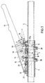
- Figure 3 illustrates that the sleeve-shaped part 4 in Region of its end facing the handle for rod 1, thus on the side of the pocket facing away from the tappet element 24 11 has a trigger element designed as a lever 29.
- the Release lever 29 is pivotally mounted in the sleeve-shaped part 4. It has a shoulder 31 in the region of its pivot axis 30 on and starting from the pivot axis 30 two essentially Legs 32 and 35 arranged at right angles to one another thigh to be loaded by hand runs approximately parallel to the longitudinal axis of the rod 1 between this and is with a Handle recess 36 provided.
- the other leg 35 is in two parts formed, each leg portion 35a and 35b laterally of the Rod 1 is arranged inside the pocket 11.
- Figure 3 illustrates the cattle obstacle device according to the invention with maximum tension lever pulled through.
- the tensioning lever 12 would have to starting from the position shown in this figure be pivoted clockwise by a little more than 90 °, first the clamping of the sleeve-shaped parts 3 and 4 the rod is achieved.
- the clamping rings 8 and 9 in transferred a position in which the rod 1 this with play enforced and thus no clamping between rod 1 and sleeve-shaped parts 3 and 4 by means of the clamping rings 8 and 9 is brought about.
- the plunger elements 23 are in this position and 24 largely inserted into the sleeve-shaped parts 3 and 4.
- the leg 32 of the release lever 29 is located in his hand - depressed position, in which the Leg parts 35a and 35b of the release lever 29 the clamping ring 9 contact on the side facing away from the tappet element 24.
- FIG. 7 illustrates that not yet fully pulled clamping lever 12, the clamping rings 8 and 9 in their clamped position.
- the tension lever 12 is only between the, not shown, forward position in the direction of the mother animal and the Moved position shown in Figure 7, the latter End position due to the attachment of the neck 32 of the clamping lever 12 is specified on the approach 31 of the trigger lever 29.
- the clamping lever 12 is released and it presses the Operator with their normally operating the clamping lever Hand the leg 32 of the release lever 29, the leg parts 35a and 35b the clamping ring 9 from the position shown in swivel the position perpendicular to the longitudinal axis of the rod 1. During the pivoting of the lever 29, it also arrives Approach 31 from the path of movement of the approach 33 of the clamping lever 12.
Landscapes
- Health & Medical Sciences (AREA)
- Life Sciences & Earth Sciences (AREA)
- Veterinary Medicine (AREA)
- Surgery (AREA)
- Engineering & Computer Science (AREA)
- Wood Science & Technology (AREA)
- Zoology (AREA)
- Animal Behavior & Ethology (AREA)
- General Health & Medical Sciences (AREA)
- Public Health (AREA)
- Accommodation For Nursing Or Treatment Tables (AREA)
Applications Claiming Priority (2)
| Application Number | Priority Date | Filing Date | Title |
|---|---|---|---|
| DE19734956A DE19734956C1 (de) | 1997-08-13 | 1997-08-13 | Gerät zur Viehgeburtshilfe |
| DE19734956 | 1997-08-13 |
Publications (2)
| Publication Number | Publication Date |
|---|---|
| EP0901774A1 true EP0901774A1 (fr) | 1999-03-17 |
| EP0901774B1 EP0901774B1 (fr) | 2001-09-12 |
Family
ID=7838772
Family Applications (1)
| Application Number | Title | Priority Date | Filing Date |
|---|---|---|---|
| EP98112114A Expired - Lifetime EP0901774B1 (fr) | 1997-08-13 | 1998-07-01 | Appareil pour aider à la parturition des bestiaux |
Country Status (2)
| Country | Link |
|---|---|
| EP (1) | EP0901774B1 (fr) |
| DE (2) | DE19734956C1 (fr) |
Families Citing this family (4)
| Publication number | Priority date | Publication date | Assignee | Title |
|---|---|---|---|---|
| BRPI0613126A2 (pt) | 2005-06-30 | 2012-12-04 | Kelsey Hayes Co | cilindro mestre, sistema de frenagem para aplicar fluido de freio hidráulico pressurizado |
| CN101896382A (zh) | 2007-10-29 | 2010-11-24 | 凯尔西-海耶斯公司 | 具有受控增压的液压制动系统 |
| US8661812B2 (en) | 2010-02-03 | 2014-03-04 | Kelsey-Hayes Company | Hydraulic brake system with controlled boost |
| WO2012058330A2 (fr) | 2010-10-26 | 2012-05-03 | Kelsey-Hayes Company | Système de freinage hydraulique à suralimentation régulée |
Citations (2)
| Publication number | Priority date | Publication date | Assignee | Title |
|---|---|---|---|---|
| EP0608790A2 (fr) | 1993-01-25 | 1994-08-03 | Rheintechnik Weiland & Kaspar KG Maschinenfabrik. | Appareil pour faciliter le vêlement |
| DE4441795C1 (de) | 1994-11-24 | 1996-06-20 | Rheintechnik Weiland & Kaspar | Gerät zur Viehgeburtshilfe |
-
1997
- 1997-08-13 DE DE19734956A patent/DE19734956C1/de not_active Expired - Lifetime
-
1998
- 1998-07-01 EP EP98112114A patent/EP0901774B1/fr not_active Expired - Lifetime
- 1998-07-01 DE DE59801433T patent/DE59801433D1/de not_active Expired - Lifetime
Patent Citations (2)
| Publication number | Priority date | Publication date | Assignee | Title |
|---|---|---|---|---|
| EP0608790A2 (fr) | 1993-01-25 | 1994-08-03 | Rheintechnik Weiland & Kaspar KG Maschinenfabrik. | Appareil pour faciliter le vêlement |
| DE4441795C1 (de) | 1994-11-24 | 1996-06-20 | Rheintechnik Weiland & Kaspar | Gerät zur Viehgeburtshilfe |
Also Published As
| Publication number | Publication date |
|---|---|
| EP0901774B1 (fr) | 2001-09-12 |
| DE19734956C1 (de) | 1998-08-20 |
| DE59801433D1 (de) | 2001-10-18 |
Similar Documents
| Publication | Publication Date | Title |
|---|---|---|
| DE69903094T2 (de) | Klemmvorrichtung | |
| EP0594946B1 (fr) | Instrument endoscopique de coupe et/ou pince endoscopique | |
| DE69013153T2 (de) | Pinzetten zum herausziehen von zecken. | |
| DE2328230C3 (de) | Insbesondere zum Schalten eines Wechselgetriebes bestimmtes Übertragungsgestänge für Fahrzeuge, insbesondere Nutzfahrzeuge, mit kippbaren Fahrerhäusern | |
| DE19521257A1 (de) | Chirurgische Zange | |
| DE3044186A1 (de) | Klammerhaltegeraet zum abklemmen von blutgefaessen | |
| DE1553692A1 (de) | Baumschere | |
| DE1919472A1 (de) | Werkzeug zum Spannen eines einem Gegenstand umgelegten Bandes und zum Verbinden und Abschneiden der Bandenden | |
| DE4010144A1 (de) | Geraet zum ausreissen von pflanzen | |
| DE10014063A1 (de) | Medizinischer oder dentalmedizinischer Behandlungsstuhl oder eine Kopfstütze für einen solchen Behandlungsstuhl | |
| DE3523058C2 (de) | Laengsverstellbare sicherheits-skibindung | |
| DE2732575C2 (de) | Verriegelungsvorrichtung | |
| EP0901774B1 (fr) | Appareil pour aider à la parturition des bestiaux | |
| DE2365921B2 (de) | Vorrichtung zum Festlegen von unter einem Flugzeug mitzufahrenden Lasten | |
| DE3739254A1 (de) | Medizinisches, insbesondere chirurgisches instrument | |
| DE4309569C1 (de) | Griff für ein chirurgisches Rohrschaftinstrument | |
| DE69201889T2 (de) | Sicherheitsskibindung. | |
| DE4441795C1 (de) | Gerät zur Viehgeburtshilfe | |
| DE19747043C2 (de) | Endoskopisches Instrument | |
| DE4301857C1 (de) | Gerät zur Viehgeburtshilfe | |
| DE3716764A1 (de) | Medizinisches, insbesondere chirurgisches instrument mit einem saugrohr | |
| EP0548302B1 (fr) | Dispositif de blocage pour outils similaires a une pince | |
| DE10113307A1 (de) | Greif- und Hebevorrichtung | |
| AT378684B (de) | Mit einer skibremse kombinierter fersenhalter | |
| DE2838925C3 (de) | Clip zum Unterbrechen von Leitungsbahnen in einem menschlichen oder tierischen Organismus und Zange zur Verwendung in Verbindung mit diesem Clip |
Legal Events
| Date | Code | Title | Description |
|---|---|---|---|
| PUAI | Public reference made under article 153(3) epc to a published international application that has entered the european phase |
Free format text: ORIGINAL CODE: 0009012 |
|
| 17P | Request for examination filed |
Effective date: 19981229 |
|
| AK | Designated contracting states |
Kind code of ref document: A1 Designated state(s): DE ES FR GB IE IT NL PT |
|
| AX | Request for extension of the european patent |
Free format text: AL;LT;LV;MK;RO;SI |
|
| RIN1 | Information on inventor provided before grant (corrected) |
Inventor name: ANDRETZKI, RAINER Inventor name: FANNEI, JOSEF |
|
| AKX | Designation fees paid |
Free format text: DE ES FR GB IE IT NL PT |
|
| RAP1 | Party data changed (applicant data changed or rights of an application transferred) |
Owner name: RHEINTECHNIK WEILAND & KASPAR GMBH & CO. KG |
|
| GRAG | Despatch of communication of intention to grant |
Free format text: ORIGINAL CODE: EPIDOS AGRA |
|
| 17Q | First examination report despatched |
Effective date: 20001127 |
|
| GRAG | Despatch of communication of intention to grant |
Free format text: ORIGINAL CODE: EPIDOS AGRA |
|
| GRAH | Despatch of communication of intention to grant a patent |
Free format text: ORIGINAL CODE: EPIDOS IGRA |
|
| GRAH | Despatch of communication of intention to grant a patent |
Free format text: ORIGINAL CODE: EPIDOS IGRA |
|
| GRAA | (expected) grant |
Free format text: ORIGINAL CODE: 0009210 |
|
| AK | Designated contracting states |
Kind code of ref document: B1 Designated state(s): DE ES FR GB IE IT NL PT |
|
| PG25 | Lapsed in a contracting state [announced via postgrant information from national office to epo] |
Ref country code: GB Free format text: LAPSE BECAUSE OF FAILURE TO SUBMIT A TRANSLATION OF THE DESCRIPTION OR TO PAY THE FEE WITHIN THE PRESCRIBED TIME-LIMIT Effective date: 20010912 |
|
| REG | Reference to a national code |
Ref country code: IE Ref legal event code: FG4D Free format text: GERMAN |
|
| REF | Corresponds to: |
Ref document number: 59801433 Country of ref document: DE Date of ref document: 20011018 |
|
| PG25 | Lapsed in a contracting state [announced via postgrant information from national office to epo] |
Ref country code: PT Free format text: LAPSE BECAUSE OF FAILURE TO SUBMIT A TRANSLATION OF THE DESCRIPTION OR TO PAY THE FEE WITHIN THE PRESCRIBED TIME-LIMIT Effective date: 20011212 |
|
| ET | Fr: translation filed | ||
| GBV | Gb: ep patent (uk) treated as always having been void in accordance with gb section 77(7)/1977 [no translation filed] |
Effective date: 20010912 |
|
| PG25 | Lapsed in a contracting state [announced via postgrant information from national office to epo] |
Ref country code: ES Free format text: LAPSE BECAUSE OF FAILURE TO SUBMIT A TRANSLATION OF THE DESCRIPTION OR TO PAY THE FEE WITHIN THE PRESCRIBED TIME-LIMIT Effective date: 20020326 |
|
| PLBE | No opposition filed within time limit |
Free format text: ORIGINAL CODE: 0009261 |
|
| STAA | Information on the status of an ep patent application or granted ep patent |
Free format text: STATUS: NO OPPOSITION FILED WITHIN TIME LIMIT |
|
| 26N | No opposition filed | ||
| REG | Reference to a national code |
Ref country code: NL Ref legal event code: SD Effective date: 20110124 |
|
| REG | Reference to a national code |
Ref country code: FR Ref legal event code: TP |
|
| REG | Reference to a national code |
Ref country code: DE Ref legal event code: R081 Ref document number: 59801433 Country of ref document: DE Owner name: RHEINTECHNIK BECKER ELEKTRONIK GMBH & CO. KG, DE Free format text: FORMER OWNER: RHEINTECHNIK WEILAND & KASPAR GMBH & CO. KG MASCHINENFABRIK HERSTELLUNG UND VERTRIEB VON ELEKTRONISCHEN, MEDIZINISCHEN UND TIERMEDIZINISCHEN ARTIKELN, 56566 NEUWIED, DE Effective date: 20110406 |
|
| PGFP | Annual fee paid to national office [announced via postgrant information from national office to epo] |
Ref country code: IE Payment date: 20140723 Year of fee payment: 17 |
|
| PGFP | Annual fee paid to national office [announced via postgrant information from national office to epo] |
Ref country code: FR Payment date: 20140721 Year of fee payment: 17 |
|
| PGFP | Annual fee paid to national office [announced via postgrant information from national office to epo] |
Ref country code: IT Payment date: 20140730 Year of fee payment: 17 |
|
| REG | Reference to a national code |
Ref country code: IE Ref legal event code: MM4A |
|
| PG25 | Lapsed in a contracting state [announced via postgrant information from national office to epo] |
Ref country code: IT Free format text: LAPSE BECAUSE OF NON-PAYMENT OF DUE FEES Effective date: 20150701 |
|
| REG | Reference to a national code |
Ref country code: FR Ref legal event code: ST Effective date: 20160331 |
|
| PG25 | Lapsed in a contracting state [announced via postgrant information from national office to epo] |
Ref country code: FR Free format text: LAPSE BECAUSE OF NON-PAYMENT OF DUE FEES Effective date: 20150731 |
|
| PG25 | Lapsed in a contracting state [announced via postgrant information from national office to epo] |
Ref country code: IE Free format text: LAPSE BECAUSE OF NON-PAYMENT OF DUE FEES Effective date: 20150701 |
|
| PGFP | Annual fee paid to national office [announced via postgrant information from national office to epo] |
Ref country code: NL Payment date: 20160720 Year of fee payment: 19 |
|
| PGFP | Annual fee paid to national office [announced via postgrant information from national office to epo] |
Ref country code: DE Payment date: 20160922 Year of fee payment: 19 |
|
| REG | Reference to a national code |
Ref country code: DE Ref legal event code: R119 Ref document number: 59801433 Country of ref document: DE |
|
| REG | Reference to a national code |
Ref country code: NL Ref legal event code: MM Effective date: 20170801 |
|
| PG25 | Lapsed in a contracting state [announced via postgrant information from national office to epo] |
Ref country code: NL Free format text: LAPSE BECAUSE OF NON-PAYMENT OF DUE FEES Effective date: 20170801 Ref country code: DE Free format text: LAPSE BECAUSE OF NON-PAYMENT OF DUE FEES Effective date: 20180201 |