EP0900953A2 - Spindeltrieb mit Abstreiferbaugruppe - Google Patents
Spindeltrieb mit Abstreiferbaugruppe Download PDFInfo
- Publication number
- EP0900953A2 EP0900953A2 EP98116855A EP98116855A EP0900953A2 EP 0900953 A2 EP0900953 A2 EP 0900953A2 EP 98116855 A EP98116855 A EP 98116855A EP 98116855 A EP98116855 A EP 98116855A EP 0900953 A2 EP0900953 A2 EP 0900953A2
- Authority
- EP
- European Patent Office
- Prior art keywords
- adapter
- spindle
- drive according
- spindle drive
- nut
- Prior art date
- Legal status (The legal status is an assumption and is not a legal conclusion. Google has not performed a legal analysis and makes no representation as to the accuracy of the status listed.)
- Granted
Links
Images


Classifications
-
- F—MECHANICAL ENGINEERING; LIGHTING; HEATING; WEAPONS; BLASTING
- F16—ENGINEERING ELEMENTS AND UNITS; GENERAL MEASURES FOR PRODUCING AND MAINTAINING EFFECTIVE FUNCTIONING OF MACHINES OR INSTALLATIONS; THERMAL INSULATION IN GENERAL
- F16H—GEARING
- F16H25/00—Gearings comprising primarily only cams, cam-followers and screw-and-nut mechanisms
- F16H25/18—Gearings comprising primarily only cams, cam-followers and screw-and-nut mechanisms for conveying or interconverting oscillating or reciprocating motions
- F16H25/20—Screw mechanisms
- F16H25/24—Elements essential to such mechanisms, e.g. screws, nuts
- F16H25/2418—Screw seals, wipers, scrapers or the like
-
- F—MECHANICAL ENGINEERING; LIGHTING; HEATING; WEAPONS; BLASTING
- F16—ENGINEERING ELEMENTS AND UNITS; GENERAL MEASURES FOR PRODUCING AND MAINTAINING EFFECTIVE FUNCTIONING OF MACHINES OR INSTALLATIONS; THERMAL INSULATION IN GENERAL
- F16H—GEARING
- F16H25/00—Gearings comprising primarily only cams, cam-followers and screw-and-nut mechanisms
- F16H25/18—Gearings comprising primarily only cams, cam-followers and screw-and-nut mechanisms for conveying or interconverting oscillating or reciprocating motions
- F16H25/20—Screw mechanisms
- F16H25/22—Screw mechanisms with balls, rollers, or similar members between the co-operating parts; Elements essential to the use of such members
- F16H25/2204—Screw mechanisms with balls, rollers, or similar members between the co-operating parts; Elements essential to the use of such members with balls
-
- Y—GENERAL TAGGING OF NEW TECHNOLOGICAL DEVELOPMENTS; GENERAL TAGGING OF CROSS-SECTIONAL TECHNOLOGIES SPANNING OVER SEVERAL SECTIONS OF THE IPC; TECHNICAL SUBJECTS COVERED BY FORMER USPC CROSS-REFERENCE ART COLLECTIONS [XRACs] AND DIGESTS
- Y10—TECHNICAL SUBJECTS COVERED BY FORMER USPC
- Y10T—TECHNICAL SUBJECTS COVERED BY FORMER US CLASSIFICATION
- Y10T74/00—Machine element or mechanism
- Y10T74/18—Mechanical movements
- Y10T74/18568—Reciprocating or oscillating to or from alternating rotary
- Y10T74/18576—Reciprocating or oscillating to or from alternating rotary including screw and nut
Definitions
- the invention relates to a spindle drive, comprising a spindle with a Spindle axis and an outer peripheral surface, one the spindle enclosing nut which is in screw engagement with this at least one in an axial end region of the nut detachably on the latter attached wiper assembly with at least one in wiping engagement with the outer circumferential surface of the scraper component.
- the wiper assembly includes an on the inner circumference a sleeve attached sealing ring, which on the back of a thread External thread of the spindle is sealing.
- the sealing ring is with the Riveted rivet.
- the one from the sealing ring and the sleeve existing scraper assembly is with the nut mounted on the spindle attachable to this.
- an axially protruding from the nut Welded pipe socket On this pipe approach the The sealing ring bearing sleeve of the wiper assembly is pushed on.
- the known solution requires adaptation work on the mother to the To be able to assemble the wiper assembly. It must be the mother Welding process to be subjected to the pipe attachment to it fasten. Should be a conventional nut available as a series component are used, so it is often not possible from the outside to weld a pipe neck to this. Often the material of the Mother or / and components connected to it, welding one Not at all due to the high heat sensitivity, severe risk of deformation or poor welding properties. this applies especially for precision spindle drives, such as those in Machine tools or measuring devices are used.
- the Welding also represents a comparatively complex and difficult process, since the tube attachment in the radial direction exactly must be positioned to be uniform over the entire circumference System conditions of the sealing ring on the back of the thread Ensure spindle thread. Also common on conventional nuts for constructional or space reasons no suitable position for Finding a pipe neck welded on. Finally, the pipe neck after welding can no longer be removed from the mother, so that the Mother is committed to a specific purpose and no longer for other uses can be used, in which an axial of The scraper assembly attached to the outside may no longer be at all is needed. The welded pipe socket would then only be annoying and would take up unnecessary space.
- Another spindle drive is from the German patent specification DT 20 01 558 with a spindle and one in screw engagement with the spindle Mother known, in the assembled state of the mother Sealing ring can be attached to this from the outside axially.
- the Sealing ring engages in a thread groove in the outer peripheral surface of the Spindle and is screwed onto the spindle from one end of the spindle.
- In an axial end face of the nut are distributed over the circumference several axially directed pin receiving holes are provided. Similar Pin receiving holes are also provided in the sealing ring.
- the pin receiving holes in the Sealing ring and the nut are covered and then with pegs occupied, which hold the sealing ring against rotation on the nut.
- the prestressing element supported on the nut becomes the sealing ring axially away from the nut against the threads of the spindle thread biased.
- the invention is therefore based on the technical problem with one Generic spindle drive an easy assembly of the Scraper assembly on the nut with the greatest possible avoidance to enable special adaptation measures on the mother.
- the invention provides that the Scraper assembly for fastening to the nut, however, non-rotatably is releasably connectable with an adapter, which in turn is axially fixed and is non-rotatable, but releasably connectable to the nut.
- the adapter which is free of stripping tasks, forms an interface between the mother and the wiper assembly. He is one of the mother and one the wiper assembly physically separate component - or a unit. On the one hand, this component or unit can be optimal to those on the mother, especially on a conventional mother, existing mounting options can be adjusted. This means that the adapter can be designed so that it can be attached to the nut without having to edit the mother specifically, for example to have to provide a welded pipe socket or holes to have to attach. The mother can then also be used for such purposes continue to be used, in which the wiper assembly with the Adapter is not desired or not necessary. On the other hand, the Adapters also optimally match those on the wiper assembly Fastening options can be adjusted.
- the wiper component in an assembled state of the nut, in which it is mounted on the spindle is mountable on and removable from the nut.
- the spindle then does not have to be removed from their spindle bearings to the Wiper component with the adapter on the nut to be able to attach. It is recommended that the adapter in the Mounting state of the mother mountable on this and from this is removable.
- the assembly of the spindle drive is further simplified if at least a part of the wiper assembly comprising the wiper component and the adapter can be pre-assembled into a structural unit and as a structural unit on the Mother can be attached.
- the pre-assembled, comprising the wiper component and the adapter Unit in an assembled state of the mother, in which this on the Spindle is mounted can be mounted on and removed from this.
- first axial stop means are provided, which the axial position of the Set the adapter relative to the mother.
- Wiper component can be connected axially fixed to the adapter. Your assembly on the adapter is then facilitated by the fact that Wiper assembly and second interacting on the adapter Axial stop means are provided, which the axial position of the Specify the wiper component relative to the adapter.
- the wiper assembly comprises a wiper component which is in a threaded groove engages the outer surface of the spindle
- the Scraper assembly for their assembly usually not axially on the Spindle are pushed on, but rather must be on the spindle be turned up.
- a simple assembly of the spindle drive without Adjustment effort is then ensured in that the attachment of the Adapters are provided on the mother fasteners, which a independent of the rotational position of the adapter relative to the nut Allow attachment of the adapter.
- the wiper assembly can physically separate at least two trained wiper components include. At least part of the Wiper components can be wiped axially one behind the other stand with the outer peripheral surface of the spindle.
- the wiper components can take on different functions, so that a highly effective scraper assembly can be realized, the mother seals perfectly to the outside. So it is conceivable that two axially successively in wiping engagement with the outer peripheral surface of the spindle standing wiper components with regard to their wiping effect differentiate.
- the sealing of the mother can be provided that in the axial end region of the nut at least one additional, from the Scraper assembly separate scraper element attached to the nut or is attachable.
- This is expediently additional Wiper element closer to an axial than the wiper assembly Central area of the mother attached to this or be attachable.
- the additional wiper element can be added to the nut Wiper element receiving groove be formed.
- Such a wiper element receiving groove is often in the form of nuts formed an annular groove into which an additional wiper element Sealing ring can be used. The user of the Spindle drive the possibility open, in addition to the wiper assembly to mount an additional sealing ring on the nut or this omit.
- the adapter an axially directed away from the mother mounting surface for attaching the Wiper assembly. Then several can be in the mounting surface in relation to the spindle axis - distributed in the circumferential direction, axial mounting holes for mounting mounting bolts be formed, the attachment of the wiper assembly to the Mounting surface of the adapter. At least part of the Fastening holes can be designed as blind holes. Alternatively or additionally, at least part of the Mounting holes go axially through the adapter, which it is allowed fastening bolts in axially from both sides of the adapter use these mounting holes.
- a fixation of the adapter on the nut in the radial direction can thereby achieved that the adapter at least one essentially in Axial direction of the spindle pointing towards the nut having.
- the bracket attachment serves to center the adapter on the Mother. If desired, such a mounting approach can also be used Fixation of the adapter can be provided in the circumferential direction.
- the Bracket approach can be designed as a ring rib or ring rib segment be.
- the mother is expedient to have at least one Bracket mount designed to accommodate the bracket attachment. This bracket mount can be from an inner peripheral surface of the nut be radially limited.
- the adapter preferably encompasses the spindle essentially completely, where it can be expediently designed as a ring part.
- a this makes it easy and quick to mount the adapter on the nut allows the adapter to circumferentially through a slit is separated, the slot width by slot width influencing means can be influenced, and that the adapter by influencing the slot width the slot can be clamped to the nut. Modifications to the mother in the form of a subsequent processing of these are the Assembly itself is not necessary, since by appropriate design of the Adapters this on essentially any existing surface of the Nut can be clamped.
- the slot width influencer can be designed as slot narrowing means, the adapter can then be clamped against an outer peripheral surface of the nut. It is also possible that the slot width influencing means as Slot expansion means are formed and the adapter against one Inner circumferential surface of the nut can be clamped.
- One for clamping suitable outer or inner circumferential surface is at conventional nuts are usually available.
- the Slot width influencing means a slot width influencing screw, which can be inserted into a hole in the adapter, which in a slot boundary surface of the slot opens. Since it's under Shelters can be difficult to thread into the hole cut, for example because the wall thickness around the hole is too small, it is preferably provided that a physical in the slit Separately trained threaded nut is held with the slot width influencing screw can be brought into thread engagement. The right one Positioning the threaded nut, it is recommended that this in a Recess arranged in a slot boundary surface of the slot is.
- the adapter by means of a hook arrangement on the mother is hooked.
- the hook arrangement preferably comprises at least two - based on the spindle axis - distributed in the circumferential direction arranged fastening hooks. These are useful for Intervention in a hooking recess of the mother is formed.
- the interlocking recess can advantageously have a circumferential groove in an inner peripheral surface or in an outer peripheral surface of the nut be educated. Such a circumferential groove is common in conventional nuts available and can be used without additional processing measures Interlocking of the adapter can be used.
- the fastening hooks are as Toggle hooks formed between a release position and a Hook position are tiltably mounted on the adapter.
- a tilting arrangement can be provided on the adapter, each on a rocking end opposite each hook end of each of the rocker arms acts.
- a space-saving and protected accommodation of the fastening hooks can be that the fastening hooks in one Hook receiving slot of the adapter are included and with a Stick the end of the hook out of its hook slot.
- the adapter is used for reasons of strength and for easy workability preferably made of metal, with a particularly light weight of the Adapters is guaranteed by the use of aluminum. It however, it goes without saying that the adapter can also be made of plastic can, for example as an injection molded part.
- any existing leaks between the adapter and the Mothers can be eliminated by having one on the mother certain contact surface of the adapter at least partially with one Material covering is provided.
- the material covering can vulcanized rubber or sprayed plastic and preferably has a certain elasticity so that it leaks between the adapter and the nut.
- the adapter is designed with a slot, it is recommended that too this slitting at least partially with particularly deformable Sealing material is filled in to prevent the ingress of contaminants to prevent the slitting.
- the Scraper assembly as a scraper component a scraper ring comprises, which essentially over its entire inner circumference in Sealing engagement with the outer peripheral surface of the spindle is.
- a good Sealing effect can be achieved if the wiper ring is preloaded is installed, which in the radial direction against the outer peripheral surface the spindle is preloaded.
- a structurally simple type of radial Preloading the scraper ring is that the scraper ring in Circumferential direction is separated at a point of separation and by separation-constricting pretensioning means can be pretensioned. It is preferred provided that the separation point from a substantially axial oriented, oblique to the radial direction separating slot or Partition cut is formed.
- the biasing means can have a biasing body with a Include preload in which the scraper ring to its Preload can be used. It can be provided that the Preload body is physically separate from the adapter and comprises a biasing sleeve into which the wiper ring can be inserted. Alternatively, it can be provided that the biasing body from the adapter is formed and the bias holder is formed on the adapter.
- the slotted design of the scraper ring not only enables its radial preload, but also the exchange of the wiper ring, without having to remove the spindle from its spindle bearings.
- the Scraper ring can namely be bent at its separation point and be pulled off the spindle at the resulting gap.
- a new Wiper ring can be assembled in the same way by bending it up and is attached to the spindle.
- Plastic is recommended as the material for the scraper ring, since it is used for one is sufficiently wear-resistant and the other is the required Can provide flexibility to the scraper ring for its assembly and To be able to bend disassembly in the manner just described.
- the Bracket formations at least two related to the spindle axis in Distributed circumferentially on one of the components: wiper ring and Adapters arranged or arranged in the axial direction of each other component protruding bracket body, which in one opposite mounting recess in the other Component can be used axially.
- the Scraper ring is slotted and the bracket body and associated Bracket recesses in the circumferential direction on both sides of the slot of the Wiper rings are localized on the two components so that the Scraper ring can be held on the adapter with radial constriction.
- the radial constriction becomes the wiper ring under a preload set that lets him hold on to the adapter as long as the Fasteners are not yet attached.
- a simple way of attaching the wiper component to the Adapter results from the fact that the wiper component of at least two - based on the spindle axis - distributed in the circumferential direction arranged through holes for receiving fastening bolts is axially penetrated, the attachment of the wiper component to the Serve adapters. It is conceivable to first attach the adapter to the nut fasten and then, if desired, any wiper components to attach such fastening bolts to the adapter. if the Wiper assembly includes multiple wiper components, the Fastening bolts through all of these wiper components go through.
- fastening bolts in the final assembly state of the Spindle drive are accessible from the outside, can be added later Wiper components are added to the wiper assembly or individual wiper components of the wiper assembly removed or can be replaced by other wiper components without the adapter from to take off the mother.
- the wiper ring is made of tightness and For reasons of cost, often make from plastic, which if tightened too much the fastening bolt, however, is subject to the risk of being crushed.
- the wiper component from a pinch-prone Material, especially plastic is made, it is advantageous if a spacer sleeve in each of the through bores of the wiper component preferably made of metal, which is at one end on the Supports adapters and other to accommodate the respective Fastening bolt generated clamping forces is formed.
- the wiper assembly can be used as one Scraper component also essentially encloses the spindle Scraper brush include those with a variety of brush hairs Brush the outer surface of the spindle.
- the Scraper assembly as a scraper component a groove scratch include the in at least one scratch projection in a thread groove engages the outer peripheral surface of the spindle.
- Both the scraper brush as well as the groove scratcher will primarily serve to rough Wipe off dirt from the outer surface of the spindle. They are expediently supplemented by a main scraper that also have fine impurities from the outer surface of the Spindle removed.
- a main scraper can be part of the Be wiper assembly or as separate from the wiper assembly Sealing element be attached directly to the nut.
- the wiper assembly can also have at least one Comprise cover element for the at least one wiper component, the cover element as a cover plate or cover plate, in particular made of sheet metal.
- the cover element serves to protect the scraper component (s) from hot chips that are in Machine tools occur when machining workpieces can.
- the cover also provides protection against that other contaminants, such as dust, on the wiper component or the wiper components, and can also protect against aggressive chemicals, coolants or lubricants.
- the solution according to the invention is preferred for a spindle drive provided in which the spindle in its outer peripheral surface at least has a screw groove running around the spindle axis.
- the spindle drive as a rolling element screw drive
- Ball screw drive is according to a preferred embodiment provided that at least one in an inner peripheral surface of the nut rolling element guides running helically around the spindle axis Nut groove is recessed with two end areas, which together with the Outer peripheral surface of the spindle one between the two end regions running, helical rolling screw path defines that this rolling element screw path through one between the two Rolling element return path running in the end regions into a nut closed rolling element circulation path is supplemented and that the Rolling path with an endless series of on the one hand in the Nut groove and on the other hand on a helical track of the The outer circumferential surface of the spindle is in readiness for rolling Rolling elements is occupied.
- the invention relates to a kit for Retrofitting a spindle drive, the spindle drive having a spindle a spindle axis and an outer peripheral surface as well as the spindle enclosing nut engaged with this screw, the kit comprising: at least one in an axial end region axially fixed and non-rotatable, but releasable with the nut connectable adapter and at least one non-rotatable, but detachable with the Scraper assembly connectable with adapter with at least one Wiper component for wiping engagement with the outer peripheral surface of the Spindle.
- Such a kit enables one conventional spindle drive with a wiper assembly equip, whereby the adapter can be structurally adapted to the nut can, so that for attaching the wiper assembly machining the Mother is not required.
- Different adapters or / and different wiper assemblies are provided that it allow for any desired application of the spindle drive and for any size and design of the spindle drive a suitable one To provide retrofit kit.
- the adapter and the individual Components of the wiper assembly can be found in the previous described manner.
- the invention relates to a movement system with at least two bodies movable relative to each other, whereby at at least one of the two bodies at least one wiper assembly is held, which bears against the other body.
- the wiper assembly by means of an adapter on one Body is held, the adapter on the one hand fixed, but detachable with one body and on the other hand firm, but detachable with the Wiper assembly is connectable.
- an adapter is not just one Movement system advantageously applicable, in which the two bodies are relative are linearly movable with respect to one another, as is the case, for example, with a Linear guide device with one on a guide rail, especially a profile rail, longitudinally guided carriage or a ball bushing which is guided longitudinally on a shaft is the case.
- the two bodies can rotate relative to one another, in particular screwable, as is the case with the Spindle drive described above is the case.
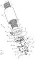
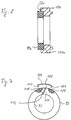
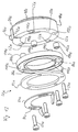
- FIG. 1 shows a ball screw drive, generally designated 10, a nut 12, a threaded spindle 14 with a spindle axis 16, an adapter 18 which can be fastened to an axial end of the nut 12 and includes a stripper assembly, generally indicated at 20, on the axially facing away from the nut 12 of the adapter 18 on this is attachable.
- the first step is Fig. 2 referenced.
- the threaded spindle 14 has one in one Outer peripheral surface 22 of the spindle 14 has a screw thread 24 on, which is executed in a catchy manner in the example shown and by one external thread groove running helically around the spindle axis 16 26 is formed. It is understood that the screw thread 24 Threaded spindle 14 also has multiple threads, for example two threads can be.
- the nut 12, which surrounds the threaded spindle 14 in a ring has at least one likewise in its inner peripheral surface 28 helically extending nut groove 30 which, like the thread groove 26 in the outer peripheral surface 22 of the spindle 14 substantially semi-circular cross-section.
- the nut groove 30 and the thread groove 26 together form a ball screw path that is not through one shown axial return channel in the nut 12 to a closed Ball circulation path is supplemented, in which an endless row of balls 32 circulates.
- Adjacent to an axial end face 34 of the nut 12 is in the Inner circumferential surface 28 incorporated a profiled recess 36.
- This profiled recess 36 comprises an annular groove closer to the end face 34 38 and an annular groove 40 further away from the end face.
- the annular grooves 38, 40 are separated from one another by an annular web 42.
- the annular groove 38 is for End face 34 bounded by an annular web 44.
- the annular groove 40 serves for receiving a locking ring, not shown, which in the annular groove 40th can be snapped and a deflection piece, also not shown on the nut 12 ensures that the balls 32 in an axial end region of the Nut 12 between the ball screw path and the ball return channel redirects.
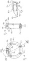
- the adapter 18 serving as the carrier of the wiper assembly 20 is on the Nut 12 can be clamped in any rotational angle position relative to mother 12. In his clamped on mother 12 The assembly state is the adapter 18 - in relation to the spindle axis 16 - both in the axial direction and in the circumferential direction on the nut 12 fixed. To explain the adapter 18, reference is first made to FIGS 6 referenced.
- the adapter 18 is designed as a ring part, the Inner diameter slightly larger than the outer diameter of the spindle 14 is. Its outer diameter is approximately the same Outside diameter of the nut 12 in the face 34 subsequent axial end area.
- the adapter 18 closes in assembled state on the outside essentially flush with the nut 12.
- annular flat surface 46 On the adapter 18 has an axially facing side of the nut 12 axially directed, annular flat surface 46, which is in contact with the surface the axial end face 34 of the nut 12 is determined.
- the plane surface 46 and the end face 34 form cooperating axial stops, which Determine the axial position of the adapter 18 relative to the nut 12.
- annular support rib 48 Of the Flat surface 46 is an annular support rib 48 substantially in axial direction before, when mounting the adapter 18 on the mother 12 inserts into the recess 36 of the nut 12 and the adapter 18 on the Inner peripheral surface 28 of the nut 12, more precisely on the Inner circumferential surface of the ring web 44, centered.
- the adapter 18 has on its side facing axially away from the nut 12 an annular, flat mounting surface 50, which is used to attach the Wiper assembly 20 is used. Axially facing away from the nut 12 Side of the adapter 18 forth are several, in the example shown four, axial Fastening bores 52 drilled in the mounting surface 50.
- the Fastening bores 52 are designed as blind threaded holes and are with approximately equal angular distances from each other over the Mounting area 50 distributed. They are used to hold Fixing screws 54 shown in Fig. 1 and for fixing serve the wiper assembly 20 on the adapter 18.
- the slot 56 passes through in the axial direction the adapter 18 through. In the circumferential direction it is divided by two opposing slot boundary surfaces 58 and 60 limited.
- a recess 62 is incorporated, which extends in the axial direction through the Adapter 18 extends through and in the radial direction from the outer circumference of the adapter 18 up to one in the circumferential direction in the slot 56 projecting web 64 is sufficient.
- the Slit delimitation surface 58 is normal to the surface Slot boundary surface 58 extending bore 66 that approximately tangential to the circumferential direction from the outer circumference of the adapter 18 in this is incorporated.
- Threaded nut 68 To clamp the adapter 18 on the nut 12 is a Threaded nut 68 inserted into the recess 62 so that it on the Web 64 rests and on the recessed part of the slot boundary surface 58 is present.
- the threaded nut 68 has a threaded hole 70 which in the inserted state of the threaded nut 68 is aligned with the bore 66. What remains after inserting the nut 68 into the recess 62 Slot volume is then at least limited elastic Sealant 72 filled.
- the sealing compound 72 prevents the penetration of Contamination from outside of the adapter 18 into that of the adapter 18 enclosed interior and holds the nut 68 in the recess 62nd
- the nut 68 is preferably encapsulated with the sealing compound 72 so that it of the sealing compound 72 not only on the slot boundary wall 58 is held, but also in the radial direction and in the axial direction is secured against loss.
- the flat surface 46 becomes at least radially outside the mounting rib 48 also covered with a sealing compound 74, which in the assembled state of the adapter 18 a sealing layer between the flat surface 46 and the axial end face 34 of the nut 12 forms.
- This sealing coating seals the Connection point formed between the adapter 18 and the nut 12 against the ingress of dirt and against the escape of Lubricant and compensates for irregularities in the flat surface 46 or / and in the axial end face 34.
- the slot filling 72 and the Sealing coating 74 are advantageously in a common If necessary, the work process can be attached in one piece.
- the sealing or filling compound used can be a rubber compound, which is applied to the adapter 18 and vulcanized there. Is conceivable but also to apply a plastic compound in one spraying process.
- the adapter 18 thus prepared is axially on the end face 34 of the nut 12 scheduled.
- the mounting rib 48 engages - as already explained - in the recess 36 on the inner circumference of the nut 12.
- a clamping screw 76 (see FIG. 1) and screwed into the threaded nut 68.
- the Clamping screw 76 is screwed into the threaded nut 68 so far that they screwed into the slot filling with their first screwed end 72 digs in.
- the clamping screw 76 is screwed in further into the Threaded nut 68 held non-rotatably in the recess 62 presses the Fixing screw 76 finally against the Slot boundary surface 60 that the adapter 18 expands. It is possible that the mounting screw 76 the material of the Slit filling 72 cuts through and in direct contact with the Slot boundary surface 60 arrives. It is also possible that the Fixing screw 76 only presses into the slot filling 72, without to hurt them.
- the slot width of slot 56 i.e. the slot volume increases.
- the sealing compound used for the slot filling 72 preferably has elasticity such that it increases the volume of the slot 56 can compensate and in the expansion of the adapter 18th the resulting additional slot volume can expand into it. This is advantageous so that not due to the additional slot volume Contaminants can penetrate or lubricants can escape.
- the threaded nut 68 is thereby always securely in the Recess 62 held.
- the adapter 18 for example if the adapter 18 is hinged by means of a joint or from a sufficiently elastic deformable material, it may also be conceivable Adapter 18 not only axially from one spindle end of the spindle 14 Slide the spindle 14, but in the radial direction onto the spindle 14 attach or subtract from this.
- the wiper assembly includes a sealing ring 80 engaging in the thread 24 of the spindle 14 the sealing ring 80, for example, to protect it from hot chips Cover plate 82 and a roughly the thread 24 of the spindle 14 pre-cleaning groove scraper 84.
- the components sealing ring 80, cover plate 82 and groove scraper 84 are by means of the fastening screws 54 on the Mounting surface 50 of the adapter 18 attachable.
- the sealing ring 80 has a set of through holes 86, the number of which the Blind holes 52 of the adapter 18 corresponds to and like that Blind holes 52 are arranged distributed in the circumferential direction, so that they can be brought into axial alignment with the blind bores 52.
- the Through holes 86 are designed without threads.
- That too Cover plate 82 has a set of through holes 88, which with the through holes 86 and the mounting holes 52 axially in Cover can be brought.
- the groove scraper 84 in Circumferential direction elongated receiving holes 90 which with the Through holes 88 of the cover plate 82 can be brought into axial overlap are. Since in the example shown in FIG. 1 the groove scratcher 84 is only one has a semicircular basic shape, it has only two receiving holes 90 while both the cover plate 82 and the sealing ring 80 each have four through holes 88 and 86, respectively.
- the sealing ring 80 has an inner circumferential surface 92, which with a thread profile 94 complementary to thread 24 of spindle 14 is executed.
- the sealing ring 80 On its side axially facing the adapter 18 the sealing ring 80 one for flat contact with the mounting surface 50 of the adapter 18 certain, axially directed contact surface 96 (see FIG. 3).
- the Sealing ring 80 On its axially facing away from the adapter 18, the Sealing ring 80 has an axially directed end face 98 into which one of the Contour of the cover plate 82 adapted receiving recess 100 is incorporated.
- the cover plate can be accommodated in this recess 100 82 positively inserted, so that it is flush with the Recess 100 recessed part of the end face 98 of the sealing ring 80 inserts.
- the cover plate 82 is designed as a segment ring, but can have any other shape sufficient for the sealing ring 80 protects against damage.
- the sealing ring 80 is advantageously made of Plastic molded, for example injection molded, with the cover plate 82 is preferably a steel sheet, but if desired also from another metal, for example brass or aluminum, or also consist of a suitable impact-resistant and heat-resistant plastic can.
- the sealing ring 80 is slotted.
- Fig. 7, which is a somewhat simplified top view of the sealing ring 80 shows.
- a separating slot 102 which runs obliquely to the radial direction, separates the sealing ring 80 at a circumferential location.
- the separation slot 102 is oriented essentially in the axial direction.
- narrowing the slot 102 is a radial preload of the sealing ring 80, which it radially against the outer peripheral surface 22 of the spindle in the assembled state 14 preloaded. It has been shown that the radial bias Sealing or wiping effect of the sealing ring 80 is considerably improved can be.
- the slot 102 must be narrowed and so the sealing ring 80 can be radially narrowed.
- a biasing clip in FIGS. 1 and 7 104 shown, which is like a bow in the circumferential direction via the separating slot 102 passed and with bent temple ends 106 in relation to the Circumferential direction arranged on both sides of the separation slot 102 Insert receptacles 108 can be inserted.
- the mutual distance of the Insert receptacle 108 in the circumferential direction is selected so that at inserted biasing clip 104 the separation slot 102 narrowed so far or is even concluded that the desired bias of the Sealing ring 80 sets.
- the through holes 86 in the sealing ring 80 are biased a slight measure compared to the mounting holes 52 in the Adapter 18 offset transversely to the axial direction. For this reason, it recommends that the through holes 86 in the sealing ring 80 a little larger cross section than the threaded sections of the fastening screws 54 have, so that a game between the fastening screws 54th and the through holes 86. It has been shown that usual Tolerances when drilling holes in plastic or metal parts are unavoidable, often enough to achieve the desired one slight play between the mounting screws 54 and To ensure through holes 86.
- the groove scraper 84 is preferably designed as a bent sheet metal part. He has a semicircular mounting portion 114 with the Receiving holes 90 and at least one axially bent Scraper section 116 at one end of the fastening section 114. For a single thread 24 of the spindle 14 is sufficient Scraper section 116 with one of the cross-sectional contour of the thread groove 26 adapted to the spindle 14, approximately crescent-shaped Scratching projection 118 is executed. In the example shown in FIG. 1 the groove scraper 84 has two scraper sections 116, which with their Scratching projections 118 for engaging a two-start thread Spindle are determined and diametrically opposite each other. The Forming the receiving holes 90 as elongated holes allows the To adjust the groove scratcher 84 in the circumferential direction relative to the adapter 18, for an optimal engagement of the scratching projections 118 in the thread 24 of the Achieve spindle 14.
- the spindle drive shown in FIG. 1 is assembled as follows: First, the nut 12 is mounted on the spindle 14, as shown in FIG. 1 is already shown. Then the individual components of the Wiper assembly 20 by means of the fastening screws 54 on the Adapter 18 attached. The biasing clip 104 must be at this time not yet be attached to the sealing ring 80, but not should be excluded. The pre-assembled unit from adapter 18, Sealing ring 80, cover plate 82 and groove scraper 84 is then attached mounted on the mother. For this purpose, the mentioned structural unit is placed on the spindle turned on what is necessary because the sealing ring 80 with its Threaded profile 94 engages in the thread 24 of the spindle 14.
- the unit is turned so far on the nut 12 until the adapter 18 with his Flat surface 46 or with the sealing coating 74 on the end face 34 of the nut 12 comes to the plant.
- the clamping screw 76 is then the adapter 18 and with it the wiper assembly 20 on the nut 12 fixed.
- An alternative procedure for the assembly of the spindle drive 10 consists of the adapter 18 on the nut mounted on the spindle 14 12 and then install the spindle 14 in their spindle bearings, before the wiper assembly 20 is mounted on the adapter 18.
- the Wiper assembly 20 can namely even with the spindle 14 installed to be assembled. Due to its separating slot 102, the Sealing ring 80 are bent apart and radially onto the spindle 14 be plugged on. The intervention of the Create the thread profile 94 with the thread 24 of the spindle 14 easily.
- the cover plate 82 can also due to its partially annular design can be easily placed radially on the spindle 14, which is also for the semi-ring shaped nut scraper 84 applies.
- the components of the Wiper assembly 20 are then secured by means of fastening screws 54 attached to the adapter 18, which in turn is fixed to the nut 12.
- the Disassembly of the spindle drive 10 can in turn in reverse order happen. Especially when only the sealing ring 80 is worn is and should be replaced, the latter is recommended Procedure, since then neither the spindle 14 from its spindle bearings must be removed, the adapter 18 dismantled from the nut 12 must become. 3 shows the assembled state of the spindle drive 10.
- FIGS. 8 to 16 For the description of FIGS. 8 to 16 - as far as it is the same or components acting in the same way - with the same reference numerals as in 1 to 7, but supplemented by a lowercase letter. To avoid repetitions, the following is essentially only on differences to the embodiment of FIGS. 1 to 7 discussed. Otherwise, reference is made to the preceding description of FIGS. 1 to 7 referred.
- Fig. 8 shows an alternative way of biasing the Sealing ring 80a. It is not as in the embodiment of FIG. 1 to 7 by a separate biasing element, namely the one there Preload clip 104, preloaded but in a circular shape in the Mounting surface 50a of the adapter 18a recessed bias mount 120a used, whose diameter is slightly smaller than the outer diameter of the Sealing ring 80a is in the relaxed state.
- a separate biasing element namely the one there Preload clip 104
- the sealing ring 80a insert into the pretension holder 120a of the adapter 18a, it is by Hand squeezed and then into the preload receptacle 120a inserted.
- the sealing ring 80a is in the preload receptacle 120a fixed both in the radial direction and in the axial direction.
- Fig. 9 shows an embodiment in which the wiper assembly 20b only the sealing ring 80b, but does not include a groove scratch. This is without further possible, provided that the spindle 14b is not heavily contaminated are to be feared that require a preliminary scraper.
- the sealing ring 80b is pretensioned in this case Embodiment in that the sealing ring 80b in one Sleeve approach 122b is used, which in the axial direction to the Cover plate 82b connects.
- the sleeve extension 122b can be made in one piece with the cover plate 82b, for example as a curved one Sheet metal part, but can also be a separately manufactured component on the Cover plate 82b may be attached, for example by gluing or Welding.
- the inner diameter of the sleeve shoulder 122b is again dimensioned slightly smaller than the outer diameter of the sealing ring 80b in the relaxed state, so that the separating slot 102b of the Sealing ring 80b narrowed and the sealing ring 80b radially biased when the cover plate 82b with the sleeve lug 122b on the Sealing ring 80b are placed.
- One of the cover plate 82b separate biasing element, such as the biasing clip 104 in FIGS. 1 and 7, can be omitted in the embodiment of FIG. 9.
- the Assembly and disassembly of the spindle drive 10b shown in FIG. 9 take place analogously to that for the exemplary embodiment of FIGS. 1 to 7 described procedure.
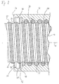
- FIG. 10 shows a spindle drive 10c, in which the stripper assembly 20c does not include a sealing ring, but only the groove scraper 84c.
- This is attached to the adapter 18c by two fastening screws, as from 1 is readily apparent. That leaves two Mounting holes of the adapter 18c unoccupied. Since the groove scraper 84c only has the effect of a pre-scraper and only coarser impurities removed from the spindle thread 24c is sufficient to achieve Sealing the nut 12c against the spindle 14c one of the Wiper assembly 20c separate sealing ring 124c in the ring groove 38c of the nut 12c used. The sealing ring is in this ring groove 38c 124c axially fixed by the ring webs 42c and 44c.
- the sealing ring 124c is preferably made of an elastomeric material and has one radially inwardly projecting annular sealing lip 126c with a Lip edge 128c on the outer peripheral surface 22c of the spindle 14c fits tightly.
- the sealing lip 126c is flexible in the axial direction deflectable so that they optimally adhere to the outer peripheral surface 22c Spindle 14c hugs.
- the sealing ring 124c is preferably radial Preload installed to increase the sealing effect. It should be noted that the assembly of the adapter 18c on the nut 12c through the sealing ring 124c is not hindered because the mounting rib 48c of the adapter 18c does not extend axially beyond the ring web 44c of the nut 12c.
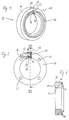
- FIGS. 11 and 12 show a spindle drive 10d, in which the adapter 18d unlike in FIGS. 1 to 10 by means of a hook arrangement 130d on the Nut 12d can be clamped.
- the hook assembly 130d includes the Embodiment shown two diametrically opposite arranged fastening hooks 132d, only one of which is shown in FIG. 11 see is.
- the mounting hooks 132d are axially of the nut 12d facing side of the adapter 18d forth in a receiving slot 134d inserted in the adapter 18d.
- Fig. 12 shows that the grub screw 140d is inserted into the threaded hole 138d can be screwed into a recess 142d of the fastening hook 132d which engages in the region of a tilting end 144d of the Fastening hook 132d lies axially of a hook end 146d of the Fastening hook 132d is opposite.
- the fastening hook 132d lies with a tilting area 148d on a shaft bottom surface 150d of the Receiving shaft 134d and is further screwed in Set screw 140d into the threaded bore 138d from a in FIG. 12 shown release position in a hooked position, in which the Fastening hook 132d with its hook end 146d behind the on the End surface 34d of the nut 12d adjacent ring rib 44d is hooked.
- the adapter 18d is axially on the nut 12d fixed.
- the Grub screw 140d loosened, which leads to the fastening hook 132d tilts back into its release position shown in FIG. 12. Of the Adapter 18d can then be removed axially from nut 12d.
- Fig. 11 it can be seen that the mounting holes 52d of the Adapters 18d pass axially through the adapter 18d and the Fastening screws 54d axially facing the nut 12d Side of the adapter 18d forth.
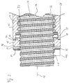
- the wiper assembly 20d comprises and 12, a wiper brush 152d made of a two-part Brush housing 154d and a brush insert 156d is constructed.
- the annular brush housing 154d is made of two semi-annular ones Housing halves 158d can be assembled and has threaded bores 160d on that with the mounting holes 52d of the adapter 18d in axial Cover can be brought and in which the fastening screws 54d are screwable to the scraper brush 152d on the mounting surface 50d to fix the adapter 18d.
- the brush insert 156d is in one annular brush receptacle 162d in the brush housing 154d applicable. It is slotted, as indicated at 164d in FIG. 11.
- the Brush insert 156d can be plugged onto spindle 14d by bending it apart, whereupon the two housing halves 158d around the brush insert 156d to the brush housing 154d getting closed.
- the adapter 18d on one of its sides axially facing the wiper brush 152d has annular centering projection 166d which is used to center the Brush housing 154d is used.
- the assembly of the spindle drive 10d of FIGS. 11 and 12 can be done in this way take place that the adapter 18d with the scraper brush 152d to one Unit is preassembled and then this unit from one Spindle end of the spindle 14d is pushed onto this.
- the spindle 14d together with the nut 12d already attached to it is then attached to the spindle bearings at their spindle ends.
- the spindle 14d installed in their spindle bearings, whereupon the brush insert 156d radially is plugged onto the spindle 14d and the brush housing 154d is attached.
- the wiper brush 152d is then replaced with the adapter 18d screwed, whereupon this assembly axially pressed on the nut 12d and by screwing in the grub screws 140d on the nut 12d is hooked.
- the disassembly of the spindle drive 10d can be done in reverse Order.
- the blind holes 52e in the adapter 18e are designed as stepped bores and one in each Have mounting surface 50e opening step-shaped extension 172e.
- Spacers 174e (see FIG. Fig. 13) used, the length of which is greater than the depth of the step-shaped Extensions 172e is. If the spacer sleeves 174e in the Step extensions 172e are used, they are therefore above the Mounting surface 50e of the adapter 18e.
- the diameter of the Through holes 86e in the sealing ring 80e corresponds to that Outer diameter of the spacer sleeves 174e.
- the Sealing ring 80e In the relaxed state of the Sealing ring 80e is also the circumferential distance between the two on both sides of the Separation slot 102e lying through holes 86e slightly larger than that Circumferential distance between the two opposite stages extensions 172e in the adapter 18e.
- the wiper assembly 20e on the Adapter 18e can thus first of all seal ring 80e into the adapter 18e inserted spacer sleeves 174e are plugged in, for this purpose the Sealing ring 80e somewhat in the area of its separating slot 102e is squeezed. This results in a radial Self-biasing of the sealing ring 80e, which it without falling off the adapter 18e holds when released by the assembler becomes.
- the length of the spacer sleeves 174e is preferably such that it protrude somewhat into the recess 100e of the sealing ring 80e into which the cover plate 82e is used.
- the cover plate 82e is then at the assembly of the wiper assembly 20e against the spacer sleeves 174e pressed, which in turn is in the step extensions 172e of the adapter Support 18e.
- the fastening screws 54e thus takes place no axial crushing of the preferably made of plastic Sealing ring 80e. Since the adapter 18e, the spacer sleeves 174e and that Cover plate 82e preferably made of metal that is not subject to crushing exist, the mounting screws 54e can still be so tight be tightened so that they are even in strong operational conditions Do not solve vibrations.
- determining a suitable Tightening torque for the fastening screws 54e not the Temperature dependence of the material hardness of the sealing ring 80e be taken into account.
Abstract
Description
- Fig. 1
- eine perspektivische Explosionsdarstellung eines ersten Ausführungsbeispiels des erfindungsgemäßen Spindeltriebs;
- Fig. 2
- eine Spindel und im Längsschnitt eine auf der Spindel montierte Mutter des Spindeltriebs der Fig. 1;
- Fig. 3
- eine Montagedarstellung des Spindeltriebs der Fig. 1 in einer Ansicht ähnlich Fig. 2;
- Fig. 4
- eine perspektivische Ansicht eines Adapters des Spindeltriebs der Fig. 1;
- Fig. 5
- eine Ansicht des Adapters der Fig. 4 in Blickrichtung des Pfeils V, wobei in einen Schlitz des Adapters eine Gewindemutter eingesetzt und der Schlitz durch eine Dichtmasse ausgefüllt ist;
- Fig. 6
- einen Schnitt längs der Linie VI - VI der Fig. 5;
- Fig. 7
- einen Dichtungsring und eine Vorspannklammer des Spindeltriebs der Fig. 1;
- Fig. 8
- eine Abwandlung eines Dichtungsrings und eines Adapters;
- Fig. 9
- eine perspektivische Explosionsdarstellung eines weiteren Ausführungsbeispiels des erfindungsgemäßen Spindeltriebs;
- Fig. 10
- in einer Ansicht ähnlich Fig. 3 ein weiteres Ausführungsbeispiel des erfindungsgemäßen Spindeltriebs;
- Fig. 11
- eine perspektivische Explosionsdarstellung eines weiteren Ausführungsbeispiels des erfindungsgemäßen Spindeltriebs;
- Fig. 12
- im Längsschnitt einen Ausschnitt des Spindeltriebs der Fig. 11;
- Fig. 13
- eine perspektivische Explosionsdarstellung eines weiteren Ausführungsbeispiels einer Abstreiferbaugruppe mit Adapter;
- Fig. 14
- eine Stirnansicht des Adapters der Fig. 13 von dessen mutternferner Seite her;
- Fig. 15
- den in Fig. 14 mit XV bezeichneten Ausschnitt in vergrößerter Darstellung; und
- Fig. 16
- einen Schnitt längs der Linie XVI-XVI der Fig. 14.
Claims (75)
- Spindeltrieb, umfassendeine Spindel (14) mit einer Spindelachse (16) und einer Außenumfangsfläche (22),eine die Spindel (14) umschließende, mit dieser in Schraubeingriff stehende Mutter (12) undmindestens eine in einem axialen Endbereich der Mutter (12) lösbar an dieser befestigte Abstreiferbaugruppe (20) mit mindestens einer in Abstreifeingriff mit der Außenumfangsfläche (22) der Spindel (14) stehenden Abstreiferkomponente (80, 84), dadurch gekennzeichnet, daß die Abstreiferbaugruppe (20) zu ihrer Befestigung an der Mutter (12) drehfest, jedoch lösbar mit einem Adapter (18) verbindbar ist, der seinerseits axial fest und drehfest, jedoch lösbar mit der Mutter (12) verbindbar ist.
- Spindeltrieb nach Anspruch 1,
dadurch gekennzeichnet, daß zumindest die Abstreiferkomponente in einem Montagezustand der Mutter, in dem diese auf der Spindel montiert ist, an der Mutter montierbar und von dieser demontierbar ist. - Spindeltrieb nach Anspruch 2,
dadurch gekennzeichnet, daß auch der Adapter in dem Montagezustand der Mutter an dieser montierbar und von dieser demontierbar ist. - Spindeltrieb nach einem der Ansprüche 1 bis 3,
dadurch gekennzeichnet, daß wenigstens ein die Abstreiferkomponente umfassender Teil der Abstreiferbaugruppe und der Adapter zu einer Baueinheit vormontierbar sind und als Baueinheit an der Mutter anbringbar sind. - Spindeltrieb nach Anspruch 4,
dadurch gekennzeichnet, daß die vormontierte, die Abstreiferkomponente und den Adapter umfassende Baueinheit in einem Montagezustand der Mutter, in dem diese auf der Spindel montiert ist, an dieser montierbar und von dieser demontierbar ist. - Spindeltrieb nach einem der Ansprüche 1 bis 5,
dadurch gekennzeichnet, daß an dem Adapter und an der Mutter zusammenwirkende erste Axialanschlagmittel vorgesehen sind, welche die Axialposition des Adapters relativ zur Mutter festlegen. - Spindeltrieb nach einem der Ansprüche 1 bis 6,
dadurch gekennzeichnet, daß die Abstreiferkomponente axial fest mit dem Adapter verbindbar ist. - Spindeltrieb nach Anspruch 7,
dadurch gekennzeichnet, daß an der Abstreiferbaugruppe und an dem Adapter zusammenwirkende zweite Axialanschlagmittel vorgesehen sind, welche die Axialposition der Abstreiferkomponente relativ zum Adapter festlegen. - Spindeltrieb nach einem der Ansprüche 1 bis 8,
dadurch gekennzeichnet, daß zur Befestigung des Adapters an der Mutter und zur Befestigung der Abstreiferbaugruppe an dem Adapter jeweils gesonderte Befestigungsorgane vorgesehen sind. - Spindeltrieb nach einem der Ansprüche 1 bis 9,
dadurch gekennzeichnet, daß zur Befestigung des Adapters an der Mutter Befestigungsmittel vorgesehen sind, welche eine von der Drehstellung des Adapters relativ zur Mutter unabhängige Befestigung des Adapters erlauben. - Spindeltrieb nach einem der Ansprüche 1 bis 10,
dadurch gekennzeichnet, daß der Adapter zur wahlweisen Befestigung unterschiedlicher Abstreiferbaugruppen ausgebildet ist, die sich hinsichtlich der Zahl oder/und der Gestaltung ihrer Abstreiferkomponenten unterscheiden. - Spindeltrieb nach Anspruch 11,
dadurch gekennzeichnet, daß der Adapter zur Anbringung einer Abstreiferbaugruppe Anbringungsstellen aufweist, die für verschiedene Abstreiferbaugruppen gleich sind. - Spindeltrieb nach einem der Ansprüche 1 bis 12,
dadurch gekennzeichnet, daß die Abstreiferbaugruppe mindestens zwei körperlich gesondert ausgebildete Abstreiferkomponenten umfaßt. - Spindeltrieb nach Anspruch 13,
dadurch gekennzeichnet, daß zumindest ein Teil der Abstreiferkomponenten axial hintereinander in Abstreifeingriff mit der Außenumfangsfläche der Spindel steht. - Spindeltrieb nach Anspruch 14,
dadurch gekennzeichnet, daß sich zwei axial hintereinander in Abstreifeingriff mit der Außenumfangsfläche der Spindel stehende Abstreiferkomponenten hinsichtlich ihrer Abstreifwirkung unterscheiden. - Spindeltrieb nach Anspruch 15,
dadurch gekennzeichnet, daß eine von einem axialen Zentralbereich der Mutter weiter entfernt in Abstreifeingriff mit der Außenumfangsfläche der Spindel stehende Abstreiferkomponente einen Vorabstreifer mit gröberer Abstreifwirkung bildet und eine näher an dem axialen Zentralbereich der Mutter in Abstreifeingriff mit der Außenumfangsfläche der Spindel stehende Abstreiferkomponente einen Hauptabstreifer mit feinerer Abstreifwirkung bildet. - Spindeltrieb nach einem der Ansprüche 1 bis 16,
dadurch gekennzeichnet, daß in dem axialen Endbereich der Mutter mindestens ein zusätzliches, von der Abstreiferbaugruppe gesondertes Abstreiferelement an der Mutter befestigt oder befestigbar ist. - Spindeltrieb nach Anspruch 17,
dadurch gekennzeichnet, daß das zusätzliche Abstreiferelement näher als die Abstreiferbaugruppe zu einem axialen Zentralbereich der Mutter hin an dieser befestigt oder befestigbar ist. - Spindeltrieb nach Anspruch 17 oder 18,
dadurch gekennzeichnet, daß an der Mutter eine Abstreiferelementenaufnahmenut zur Aufnahme des zusätzlichen Abstreiferelements ausgebildet ist. - Spindeltrieb nach Anspruch 19,
dadurch gekennzeichnet, daß die Abstreiferelementenaufnahmenut als Ringnut und das zusätzliche Abstreiferelement als Dichtungsring ausgebildet sind. - Spindeltrieb nach einem der Ansprüche 1 bis 20,
dadurch gekennzeichnet, daß der Adapter eine axial von der Mutter weg gerichtete Montagefläche zur Befestigung der Abstreiferbaugruppe aufweist. - Spindeltrieb nach Anspruch 21,
dadurch gekennzeichnet, daß in der Montagefläche mehrere - bezogen auf die Spindelachse - in Umfangsrichtung verteilt angeordnete, axiale Befestigungsbohrungen zur Aufnahme von Befestigungsbolzen ausgebildet sind, die der Befestigung der Abstreiferbaugruppe an der Montagefläche des Adapters dienen. - Spindeltrieb nach Anspruch 22,
dadurch gekennzeichnet, daß wenigstens ein Teil der Befestigungsbohrungen als Sacklochbohrungen ausgebildet ist. - Spindeltrieb nach Anspruch 22 oder 23,
dadurch gekennzeichnet, daß wenigstens ein Teil der Befestigungsbohrungen axial durch den Adapter hindurchgeht. - Spindeltrieb nach einem der Ansprüche 1 bis 24,
dadurch gekennzeichnet, daß der Adapter mindestens einen im wesentlichen in Achsrichtung der Spindel zur Mutter hin weisenden Halterungsansatz aufweist. - Spindeltrieb nach Anspruch 25,
dadurch gekennzeichnet, daß der Halterungsansatz als Ringrippe oder Ringrippensegment ausgebildet ist. - Spindeltrieb nach Anspruch 25 oder 26,
dadurch gekennzeichnet, daß die Mutter mit wenigstens einer Halterungsaufnahme zur Aufnahme des Halterungsansatzes ausgeführt ist. - Spindeltrieb nach Anspruch 27,
dadurch gekennzeichnet, daß die Halterungsaufnahme von einer Innenumfangsfläche der Mutter radial begrenzt ist. - Spindeltrieb nach einem der Ansprüche 1 bis 28,
dadurch gekennzeichnet, daß der Adapter die Spindel im wesentlichen vollständig umgreift, insbesondere als Ringteil ausgebildet ist. - Spindeltrieb nach Anspruch 29,
dadurch gekennzeichnet, daß der Adapter in Umfangsrichtung durch eine Schlitzung aufgetrennt ist, deren Schlitzweite durch Schlitzweitenbeeinflussungsmittel beeinflußbar ist, und daß der Adapter durch Beeinflussung der Schlitzweite der Schlitzung an der Mutter festklemmbar ist. - Spindeltrieb nach Anspruch 30,
dadurch gekennzeichnet, daß die Schlitzweitenbeeinflussungsmittel als Schlitzeinengungsmittel ausgebildet sind und der Adapter gegen eine Außenumfangsfläche der Mutter festklemmbar ist. - Spindeltrieb nach Anspruch 30,
dadurch gekennzeichnet, daß die Schlitzweitenbeeinflussungsmittel als Schlitzaufweitungsmittel ausgebildet sind und der Adapter gegen eine Innenumfangsfläche der Mutter festklemmbar ist. - Spindeltrieb nach Anspruch nach einem der Ansprüche 30 bis 32,
dadurch gekennzeichnet, daß die Schlitzweitenbeeinflussungsmittel eine Schlitzweitenbeeinflussungsschraube umfassen, die in eine Bohrung in dem Adapter einsetzbar ist, die in eine Schlitzbegrenzungsfläche der Schlitzung mündet. - Spindeltrieb nach Anspruch 33,
dadurch gekennzeichnet, daß in der Schlitzung eine körperlich gesondert ausgebildete Gewindemutter gehalten ist, mit der die Schlitzweitenbeeinflussungsschraube in Gewindeeingriff bringbar ist. - Spindeltrieb nach Anspruch 34,
dadurch gekennzeichnet, daß die Gewindemutter in einer Ausnehmung in einer Schlitzbegrenzungsfläche der Schlitzung angeordnet ist. - Spindeltrieb nach einem der Ansprüche 1 bis 29,
dadurch gekennzeichnet, daß der Adapter mittels einer Hakenanordnung an der Mutter verhakbar ist. - Spindeltrieb nach Anspruch 36,
dadurch gekennzeichnet, daß die Hakenanordnung mindestens zwei - bezogen auf die Spindelachse - in Umfangsrichtung verteilt angeordnete Befestigungshaken umfaßt. - Spindeltrieb nach Anspruch 37,
dadurch gekennzeichnet, daß die Befestigungshaken zum Eingriff in eine Verhakungsausnehmung der Mutter ausgebildet sind. - Spindeltrieb nach Anspruch 38,
dadurch gekennzeichnet, daß die Verhakungsausnehmung von einer Umfangsnut in einer Innenumfangsfläche der Mutter gebildet ist. - Spindeltrieb nach Anspruch 38,
dadurch gekennzeichnet, daß die Verhakungsausnehmung von einer Umfangsnut in einer Außenumfangsfläche der Mutter gebildet ist. - Spindeltrieb nach einem der Ansprüche 37 bis 40,
dadurch gekennzeichnet, daß die Befestigungshaken als Kipphaken ausgebildet sind, die zwischen einer Lösestellung und einer Verhakungsstellung kippbar an dem Adapter gelagert sind. - Spindeltrieb nach Anspruch 41,
dadurch gekennzeichnet, daß zur Überführung der Kipphaken aus ihrer Lösestellung in ihre Verhakungsstellung eine Verkippungsanordnung an dem Adapter vorgesehen ist, die jeweils auf ein einem Hakenende entgegengesetztes Kippende jedes der Kipphebel einwirkt. - Spindeltrieb nach Anspruch 42,
dadurch gekennzeichnet, daß die Verkippungsanordnung je eine Verkippungsschraube für jeden der Kipphaken umfaßt, die in eine Gewindebohrung in dem Adapter einsetzbar ist und auf das Kippende des zugehörigen Kipphakens einwirkt. - Spindeltrieb nach einem der Ansprüche 37 bis 43,
dadurch gekennzeichnet, daß die Befestigungshaken in je einem Hakenaufnahmeschacht des Adapters aufgenommen sind und mit einem Hakenende aus ihrem Hakenaufnahmeschacht herausragen. - Spindeltrieb nach einem der Ansprüche 1 bis 44,
dadurch gekennzeichnet, daß der Adapter aus Metall, insbesondere Aluminium, gefertigt ist. - Spindeltrieb nach einem der Ansprüche 1 bis 45,
dadurch gekennzeichnet, daß eine zur Anlage an der Mutter bestimmte Anlagefläche des Adapters wenigstens zum Teil mit einem Materialüberzug versehen ist. - Spindeltrieb nach Anspruch 46,
dadurch gekennzeichnet, daß der Materialüberzug aus aufvulkanisiertem Gummi oder aufgespritztem Kunststoff besteht. - Spindeltrieb nach einem der Ansprüche 30 bis 35,
dadurch gekennzeichnet, daß die Schlitzung zumindest teilweise mit einem insbesondere verformungsfähigen Dichtmaterial ausgefüllt ist. - Spindeltrieb nach einem der Ansprüche 1 bis 48,
dadurch gekennzeichnet, daß die Abstreiferbaugruppe als eine Abstreiferkomponente einen Abstreiferring umfaßt, der im wesentlichen über seinen gesamten Innenumfang in Dichteingriff mit der Außenumfangsfläche der Spindel steht. - Spindeltrieb nach Anspruch 49,
dadurch gekennzeichnet, daß der Abstreiferring mit Vorspannung eingebaut ist, die ihn in radialer Richtung gegen die Außenumfangsfläche der Spindel vorspannt. - Spindeltrieb nach Anspruch 50,
dadurch gekennzeichnet, daß der Abstreiferring in Umfangsrichtung an einer Trennstelle aufgetrennt ist und durch trennstellenverengende Vorspannmittel vorspannbar ist. - Spindeltrieb nach Anspruch 51,
dadurch gekennzeichnet, daß die Trennstelle von einem im wesentlichen axial orientierten, schräg zur Radialrichtung verlaufenden Trennschlitz oder Trennschnitt gebildet ist. - Spindeltrieb nach Anspruch 51 oder 52,
dadurch gekennzeichnet, daß die Vorspannmittel einen Vorspannkörper mit einer Vorspannaufnahme umfassen, in die der Abstreiferring zu seiner Vorspannung einsetzbar ist. - Spindeltrieb nach Anspruch 53,
dadurch gekennzeichnet, daß der Vorspannkörper körperlich gesondert von dem Adapter ausgebildet ist und eine Vorspannhülse umfaßt, in die der Abstreiferring einsteckbar ist. - Spindeltrieb nach Anspruch 53,
dadurch gekennzeichnet, daß der Vorspannkörper von dem Adapter gebildet ist und die Vorspannaufnahme an dem Adapter ausgebildet ist. - Spindeltrieb nach einem der Ansprüche 49 bis 55,
dadurch gekennzeichnet, daß der Abstreiferring aus Kunststoff ausgebildet ist. - Spindeltrieb nach einem der Ansprüche 49 bis 56,
dadurch gekennzeichnet, daß bei Ausbildung der Außenumfangsfläche der Spindel mit einem Gewindeprofil der Abstreiferring an seinem Innenumfang ein in das Gewindeprofil eingreifendes Negativprofil aufweist. - Spindeltrieb nach einem der Ansprüche 49 bis 57,
dadurch gekennzeichnet, daß der Abstreiferring (80e) durch Befestigungsorgane (54e) an dem Adapter (18e) fixierbar ist und dem Adapter (18e) und dem Abstreiferring (80e) Halterungsformationen (172e, 174e, 86e) zugeordnet sind, welche bereits vor Anbringung der Befestigungsorgane (54e) die Halterung des Abstreiferrings (80e) an dem Adapter (18e) gestatten. - Spindeltrieb nach Anspruch 58,
dadurch gekennzeichnet, daß die Halterungsformationen (172e, 174e, 86e) mindestens zwei bezogen auf die Spindelachse in Umfangsrichtung verteilt an einer der Komponenten: Abstreiferring (80e) und Adapter (18e) angeordnete oder anordenbare, in Achsrichtung zu der jeweils anderen Komponente vorstehende Halterungskörper (174e) umfassen, welche in je eine gegenüberliegende Halterungsausnehmung (86e) in der jeweils anderen Komponente axial einsetzbar sind. - Spindeltrieb nach Anspruch 59,
dadurch gekennzeichnet, daß der Abstreiferring (80e) geschlitzt ist und daß die Halterungskörper (174e) und die zugehörigen Halterungsausnehmungen (86e) in Umfangsrichtung beidseits der Schlitzstelle des Abstreiferrings (80e) derart an den beiden Komponenten (18e, 80e) lokalisiert sind, daß der Abstreiferring (80e) unter radialer Einengung an dem Adapter (18e) halterbar ist. - Spindeltrieb nach einem der Ansprüche 1 bis 60,
dadurch gekennzeichnet, daß die Abstreiferkomponente von mindestens zwei - bezogen auf die Spindelachse - in Umfangsrichtung verteilt angeordneten Durchgangsbohrungen zur Aufnahme von Befestigungsbolzen axial durchsetzt ist, die der Befestigung der Abstreiferkomponente an dem Adapter dienen. - Spindeltrieb nach Anspruch 61,
dadurch gekennzeichnet, daß die Abstreiferkomponente (80e) aus einem quetschgefährdeten Material, insbesondere Kunststoff gefertigt ist, und in ihre Durchgangsbohrungen (86e) je eine Distanzhülse (174e) vorzugsweise aus Metall eingesetzt ist, welche sich einenends an dem Adapter (18e) abstützt und andernends zur Aufnahme der von dem jeweiligen Befestigungsbolzen (54e) erzeugten Klemmkräfte ausgebildet ist. - Spindeltrieb nach einem der Ansprüche 1 bis 62,
dadurch gekennzeichnet, daß die Abstreiferbaugruppe als eine Abstreiferkomponente eine die Spindel im wesentlichen umschließende Abstreiferbürste umfaßt. - Spindeltrieb nach einem der Ansprüche 1 bis 63,
dadurch gekennzeichnet, daß die Abstreiferbaugruppe als eine Abstreiferkomponente einen Nutkratzer umfaßt, der mit mindestens einem Kratzvorsprung in eine Gewindenut in der Außenumfangsfläche der Spindel eingreift. - Spindeltrieb nach einem der Ansprüche 1 bis 64,
dadurch gekennzeichnet, daß die Abstreiferbaugruppe mindestens ein Abdeckelement für die mindestens eine Abstreiferkomponente umfaßt. - Spindeltrieb nach Anspruch 65,
dadurch gekennzeichnet, daß das Abdeckelement als Abdeckscheibe oder -platte, insbesondere aus Blech, ausgebildet ist. - Spindeltrieb nach einem der Ansprüche 1 bis 66,
dadurch gekennzeichnet, daß die Spindel in ihrer Außenumfangsfläche mindestens eine schraubenartig um die Spindelachse verlaufende Gewindenut aufweist. - Spindeltrieb nach einem der Ansprüche 1 bis 67,
dadurch gekennzeichnet, daß er als Wälzkörpergewindetrieb, insbesondere Kugelgewindetrieb, ausgebildet ist. - Spindeltrieb nach Anspruch 68,
dadurch gekennzeichnet, daß in einer Innenumfangsfläche der Mutter mindestens eine schraubenförmig um die Spindelachse verlaufende wälzkörperführende Mutternut mit zwei Endbereichen eingelassen ist, die zusammen mit der Außenumfangsfläche der Spindel einen zwischen den beiden Endbereichen verlaufenden, schraubenförmigen Wälzkörperschraubweg definiert, daß dieser Wälzkörperschraubweg durch einen zwischen den beiden Endbereichen verlaufenden Wälzkörperrückführweg in der Mutter zu einem geschlossenen Wälzkörperumlaufweg ergänzt ist und daß der Wälzkörperumlaufweg mit einer endlosen Reihe von einerseits in der Mutternut und andererseits an einer schraubenförmigen Laufbahn der Außenumfangsfläche der Spindel jeweils in Abwälzbereitschaft liegenden Wälzkörpern besetzt ist. - Bausatz zur Nachrüstung eines Spindeltriebs (10), wobei der Spindeltrieb (10) eine Spindel (14) mit einer Spindelachse (16) und einer Außenumfangsfläche (22) sowie eine die Spindel (14) umschließende, mit dieser in Schraubeingriff stehende Mutter (12) umfaßt, wobei der Bausatz umfaßt:mindestens einen in einem axialen Endbereich der Mutter (12) axial fest und drehfest, jedoch lösbar mit der Mutter (12) verbindbaren Adapter (18) undmindestens eine drehfest, jedoch lösbar mit dem Adapter (18) verbindbare Abstreiferbaugruppe (20) mit mindestens einer Abstreiferkomponente (80, 84) zum Abstreifeingriff mit der Außenumfangsfläche (22) der Spindel (14).
- Bausatz nach Anspruch 70, gekennzeichnet durch weitere Merkmale eines der Ansprüche 2 bis 69.
- Bewegungssystem mit mindestens zwei relativ zueinander beweglichen Körpern (12, 14), wobei an mindestens einem (12) der beiden Körper (12, 14) mindestens eine Abstreiferbaugruppe (20) gehalten ist, die an dem anderen Körper (14) abstreifend anliegt, insbesondere nach einem der Ansprüche 1 bis 69, dadurch gekennzeichnet, daß die Abstreiferbaugruppe (20) unter Vermittlung eines Adapters (18) an dem einen Körper (12) gehalten ist, wobei der Adapter (18) einerseits fest, jedoch lösbar mit dem einen Körper (12) und andererseits fest, jedoch lösbar mit der Abstreiferbaugruppe (20) verbindbar ist.
- Bewegungssystem nach Anspruch 72,
dadurch gekennzeichnet, daß die beiden Körper (12, 14) relativ zueinander linearbeweglich sind. - Bewegungssystem nach Anspruch 72,
dadurch gekennzeichnet, daß die beiden Körper (12, 14) relativ zueinander drehbeweglich sind. - Bewegungssystem nach Anspruch 74,
dadurch gekennzeichnet, daß die beiden Körper (12, 14) relativ zueinander schraubbeweglich sind.
Applications Claiming Priority (2)
| Application Number | Priority Date | Filing Date | Title |
|---|---|---|---|
| DE19739216A DE19739216C2 (de) | 1997-09-08 | 1997-09-08 | Spindeltrieb |
| DE19739216 | 1997-09-08 |
Publications (3)
| Publication Number | Publication Date |
|---|---|
| EP0900953A2 true EP0900953A2 (de) | 1999-03-10 |
| EP0900953A3 EP0900953A3 (de) | 2000-04-19 |
| EP0900953B1 EP0900953B1 (de) | 2003-10-29 |
Family
ID=7841539
Family Applications (1)
| Application Number | Title | Priority Date | Filing Date |
|---|---|---|---|
| EP98116855A Expired - Lifetime EP0900953B1 (de) | 1997-09-08 | 1998-09-07 | Spindeltrieb mit Abstreiferbaugruppe |
Country Status (4)
| Country | Link |
|---|---|
| US (1) | US6199440B1 (de) |
| EP (1) | EP0900953B1 (de) |
| JP (1) | JP3187012B2 (de) |
| DE (2) | DE19739216C2 (de) |
Cited By (1)
| Publication number | Priority date | Publication date | Assignee | Title |
|---|---|---|---|---|
| WO2018009436A1 (en) * | 2016-07-06 | 2018-01-11 | Amcol International Corporation | Filter and filtering method |
Families Citing this family (19)
| Publication number | Priority date | Publication date | Assignee | Title |
|---|---|---|---|---|
| KR100255216B1 (ko) | 1997-03-06 | 2000-05-01 | 윤종용 | 하드 디스크 드라이브의 엠베디드 서보라이팅 방법 |
| JP2001304372A (ja) * | 2000-04-25 | 2001-10-31 | Nsk Ltd | ボールねじ装置 |
| EP1369608A3 (de) * | 2002-05-23 | 2005-06-01 | Nsk Ltd | Linearführung |
| KR100971981B1 (ko) | 2003-04-24 | 2010-07-23 | 주식회사 포스코 | 스크류의 오일 씰링장치 |
| US7100465B1 (en) * | 2003-06-05 | 2006-09-05 | Venture Mfg, Co. | Actuator |
| DE10347360B4 (de) * | 2003-10-11 | 2021-07-01 | Robert Bosch Gmbh | Führung mit Messeinrichtung und Verfahren zur Herstellung einer solchen Führung |
| US8408087B2 (en) * | 2004-10-29 | 2013-04-02 | Thk Co., Ltd. | Screw device with sound insulating member |
| US7383623B2 (en) * | 2006-04-28 | 2008-06-10 | Kozik Pawel R | Assembly and method for vent installation |
| JP5032369B2 (ja) * | 2008-02-29 | 2012-09-26 | Thk株式会社 | ねじ装置用交換式シール装置及びねじ装置の潤滑剤塗布方法 |
| JP4834067B2 (ja) * | 2008-12-26 | 2011-12-07 | 上銀科技股▲分▼有限公司 | ボールスクリュー |
| JP5012833B2 (ja) * | 2009-02-24 | 2012-08-29 | 日本精工株式会社 | ボールねじ |
| US8147228B2 (en) * | 2009-06-22 | 2012-04-03 | Robbins & Myers Energy Systems, L.P. | Progressing cavity pump/motor |
| JP5418667B2 (ja) | 2010-03-17 | 2014-02-19 | 日本精工株式会社 | ボールねじ、及びボールねじ用ナットの製造方法 |
| JP5546320B2 (ja) * | 2010-04-01 | 2014-07-09 | ヤマハ発動機株式会社 | ロボット |
| DE202011108136U1 (de) * | 2011-11-22 | 2013-02-25 | Robert Bosch Gmbh | Gewindetrieb mit Enddichtung welche eine Montagemarkierung aufweist |
| FR2984443B1 (fr) * | 2011-12-16 | 2014-01-17 | Skf Ab | Vis a rouleaux. |
| KR200481981Y1 (ko) * | 2015-04-13 | 2016-12-02 | 하이윈 테크놀로지스 코포레이션 | 스크레이퍼를 구비한 볼 스크류 |
| DE102016209036A1 (de) * | 2016-05-24 | 2017-12-14 | Zf Friedrichshafen Ag | Spindelantrieb und Aktuator mit Spindelantrieb |
| EP3722639B1 (de) | 2018-01-19 | 2022-04-06 | Nsk Ltd. | Mutter, förderschneckenmechanismus und elektrische positionsverstellvorrichtung für ein lenkrad |
Citations (8)
| Publication number | Priority date | Publication date | Assignee | Title |
|---|---|---|---|---|
| US2548848A (en) * | 1945-10-22 | 1951-04-10 | William C Uphoff | Readily removable way wiping means |
| US2818745A (en) * | 1955-02-11 | 1958-01-07 | Cleveland Pneumatic Tool Co | Screw cleaning device |
| US2982145A (en) * | 1958-07-14 | 1961-05-02 | Orner Harry | Reciprocable feed mechanism |
| DE7137781U (de) * | 1972-11-23 | Hennig A | Abdeckung, insbesondere für Teile wie Führungsbahnen von Werkzeugmaschinen | |
| DE2540942A1 (de) * | 1975-09-13 | 1977-03-24 | Gehring Gmbh Maschf | Honvorrichtung |
| DD252994A1 (de) * | 1986-10-02 | 1988-01-06 | Grossdrehmaschbau 8 Mai Veb | Abstreifer fuer waelzschraubtrieb |
| DE3641682A1 (de) * | 1986-12-08 | 1988-06-16 | Kugelfischer G Schaefer & Co | Dichtung fuer einen kugelgewindetrieb |
| DE3902273A1 (de) * | 1989-01-26 | 1990-08-02 | Mannesmann Maschf | Vorrichtung zur stufenlosen einstellung der vorspannung der doppelmutter eines schraubtriebs, insbesondere eines kugelschraubtriebs |
Family Cites Families (15)
| Publication number | Priority date | Publication date | Assignee | Title |
|---|---|---|---|---|
| DE252994C (de) | ||||
| US2793538A (en) * | 1955-12-16 | 1957-05-28 | Beaver Prec Products Inc | Wiper for screw threads |
| SE327871B (de) * | 1969-01-16 | 1970-08-31 | Skf Svenska Kullagerfab Ab | |
| US3669456A (en) * | 1969-02-21 | 1972-06-13 | Beltek Corp | Cassette mounting and dismounting device |
| US3669460A (en) | 1971-02-22 | 1972-06-13 | Schrillo Co | A screw seal |
| US4053167A (en) * | 1976-10-18 | 1977-10-11 | Parker-Hannifin Corporation | Seal for ball bearing screws and the like |
| DE2822560A1 (de) * | 1978-05-20 | 1979-11-29 | Howard Machinery Ltd | Radialdichtung fuer gewindespindel |
| DE2928717A1 (de) | 1979-07-16 | 1981-01-29 | Star Kugelhalter Gmbh Dt | Dichtung fuer einen kugelschraubtrieb |
| JPS5785648A (en) | 1980-11-14 | 1982-05-28 | Nippon Steel Corp | Method for casting of ingot |
| JPS60164158A (ja) | 1984-02-07 | 1985-08-27 | Matsushita Electric Ind Co Ltd | ヒ−トポンプ給湯装置 |
| JPS63171757A (ja) | 1987-01-08 | 1988-07-15 | L I C:Kk | 紙状体搬送装置 |
| IT1245496B (it) | 1991-01-25 | 1994-09-27 | Ricerca Elettromeccanica Srl | Attuatore lineare a vite e/o circolazione di sfere |
| JPH0647762A (ja) | 1992-07-29 | 1994-02-22 | Ntn Corp | 金属不活性剤を含有する四フッ化エチレン樹脂組成物の成形方法 |
| JP3435856B2 (ja) * | 1994-11-15 | 2003-08-11 | 日本精工株式会社 | ボールねじ装置 |
| DE29504812U1 (de) | 1995-03-21 | 1995-05-18 | Star Gmbh | Wälzkörperschraubtrieb |
-
1997
- 1997-09-08 DE DE19739216A patent/DE19739216C2/de not_active Expired - Fee Related
-
1998
- 1998-09-07 JP JP25301698A patent/JP3187012B2/ja not_active Expired - Fee Related
- 1998-09-07 EP EP98116855A patent/EP0900953B1/de not_active Expired - Lifetime
- 1998-09-07 DE DE59810009T patent/DE59810009D1/de not_active Expired - Fee Related
- 1998-09-08 US US09/149,801 patent/US6199440B1/en not_active Expired - Fee Related
Patent Citations (8)
| Publication number | Priority date | Publication date | Assignee | Title |
|---|---|---|---|---|
| DE7137781U (de) * | 1972-11-23 | Hennig A | Abdeckung, insbesondere für Teile wie Führungsbahnen von Werkzeugmaschinen | |
| US2548848A (en) * | 1945-10-22 | 1951-04-10 | William C Uphoff | Readily removable way wiping means |
| US2818745A (en) * | 1955-02-11 | 1958-01-07 | Cleveland Pneumatic Tool Co | Screw cleaning device |
| US2982145A (en) * | 1958-07-14 | 1961-05-02 | Orner Harry | Reciprocable feed mechanism |
| DE2540942A1 (de) * | 1975-09-13 | 1977-03-24 | Gehring Gmbh Maschf | Honvorrichtung |
| DD252994A1 (de) * | 1986-10-02 | 1988-01-06 | Grossdrehmaschbau 8 Mai Veb | Abstreifer fuer waelzschraubtrieb |
| DE3641682A1 (de) * | 1986-12-08 | 1988-06-16 | Kugelfischer G Schaefer & Co | Dichtung fuer einen kugelgewindetrieb |
| DE3902273A1 (de) * | 1989-01-26 | 1990-08-02 | Mannesmann Maschf | Vorrichtung zur stufenlosen einstellung der vorspannung der doppelmutter eines schraubtriebs, insbesondere eines kugelschraubtriebs |
Cited By (1)
| Publication number | Priority date | Publication date | Assignee | Title |
|---|---|---|---|---|
| WO2018009436A1 (en) * | 2016-07-06 | 2018-01-11 | Amcol International Corporation | Filter and filtering method |
Also Published As
| Publication number | Publication date |
|---|---|
| JP3187012B2 (ja) | 2001-07-11 |
| JPH11159594A (ja) | 1999-06-15 |
| EP0900953A3 (de) | 2000-04-19 |
| DE19739216C2 (de) | 1999-07-08 |
| US6199440B1 (en) | 2001-03-13 |
| DE59810009D1 (de) | 2003-12-04 |
| EP0900953B1 (de) | 2003-10-29 |
| DE19739216A1 (de) | 1999-03-25 |
Similar Documents
| Publication | Publication Date | Title |
|---|---|---|
| EP0900953B1 (de) | Spindeltrieb mit Abstreiferbaugruppe | |
| DE19981585B4 (de) | Anordnung zur Befestigung eines rohrförmigen Elements an einem Strukturelement einer Kraftfahrzeugkarosserie | |
| DE3602500C2 (de) | ||
| EP0339357B1 (de) | Schneidmesser | |
| DE2819744C2 (de) | Scharnier, insbesondere Brillenscharnier | |
| DE19807822B4 (de) | Schwenklager | |
| EP1949014A1 (de) | Handschutzanordnung, laufanordnung und waffe | |
| DE102006010270B4 (de) | Zahnradanordnung | |
| DE2531214C2 (de) | Schraubenschlüssel in Form eines Spannfutters | |
| DE3833409C2 (de) | ||
| DE102005001535B3 (de) | Befestigungsanordnung für einen Meißel und Demontagewerkzeug | |
| DE102006033852A1 (de) | Schmiereinheit | |
| DE3031216A1 (de) | Spannfutter fuer gewindebohrer. | |
| DE3017452A1 (de) | Gleitlager, insbesondere fuer kreuzgelenkzapfen | |
| DE202005016390U1 (de) | Vorrichtung zur Führung eines Fadens | |
| EP0952053A2 (de) | Vorrichtung zur Befestigung einer Wischanlage an einem Fahrzeug | |
| DE69909341T2 (de) | Gelenkbesen | |
| EP0670148A1 (de) | Motorhandstück, insbesondere für medizinische Zwecke, vorzugsweise für ein medizinisches oder dentales Labor | |
| EP0670149A1 (de) | Gerades Motorhandstück, insbesondere für medizinische Zwecke, vorzugsweise für ein medizinisches oder dentales Labor | |
| DE2636442A1 (de) | Scheibenbremse | |
| EP0428064B1 (de) | Kunststoffgleitlager | |
| DE69725185T2 (de) | Handbetätigtes futter | |
| DE3002383B2 (de) | Reibrollgetriebe zum Umwandeln einer Drehbewegung in eine Längsbewegung und umgekehrt | |
| DE102018119980A1 (de) | Spann- oder Greifeinrichtung | |
| DE4224665C2 (de) | Scherblattträger einer Heckenschere |
Legal Events
| Date | Code | Title | Description |
|---|---|---|---|
| PUAI | Public reference made under article 153(3) epc to a published international application that has entered the european phase |
Free format text: ORIGINAL CODE: 0009012 |
|
| AK | Designated contracting states |
Kind code of ref document: A2 Designated state(s): DE FR GB IT |
|
| AX | Request for extension of the european patent |
Free format text: AL;LT;LV;MK;RO;SI |
|
| PUAL | Search report despatched |
Free format text: ORIGINAL CODE: 0009013 |
|
| AK | Designated contracting states |
Kind code of ref document: A3 Designated state(s): AT BE CH CY DE DK ES FI FR GB GR IE IT LI LU MC NL PT SE |
|
| AX | Request for extension of the european patent |
Free format text: AL;LT;LV;MK;RO;SI |
|
| 17P | Request for examination filed |
Effective date: 20000523 |
|
| AKX | Designation fees paid |
Free format text: DE FR GB IT |
|
| 17Q | First examination report despatched |
Effective date: 20011017 |
|
| GRAH | Despatch of communication of intention to grant a patent |
Free format text: ORIGINAL CODE: EPIDOS IGRA |
|
| GRAS | Grant fee paid |
Free format text: ORIGINAL CODE: EPIDOSNIGR3 |
|
| GRAA | (expected) grant |
Free format text: ORIGINAL CODE: 0009210 |
|
| AK | Designated contracting states |
Kind code of ref document: B1 Designated state(s): DE FR GB IT |
|
| PG25 | Lapsed in a contracting state [announced via postgrant information from national office to epo] |
Ref country code: GB Free format text: LAPSE BECAUSE OF FAILURE TO SUBMIT A TRANSLATION OF THE DESCRIPTION OR TO PAY THE FEE WITHIN THE PRESCRIBED TIME-LIMIT Effective date: 20031029 Ref country code: FR Free format text: LAPSE BECAUSE OF FAILURE TO SUBMIT A TRANSLATION OF THE DESCRIPTION OR TO PAY THE FEE WITHIN THE PRESCRIBED TIME-LIMIT Effective date: 20031029 |
|
| REG | Reference to a national code |
Ref country code: GB Ref legal event code: FG4D Free format text: NOT ENGLISH |
|
| REF | Corresponds to: |
Ref document number: 59810009 Country of ref document: DE Date of ref document: 20031204 Kind code of ref document: P |
|
| GBV | Gb: ep patent (uk) treated as always having been void in accordance with gb section 77(7)/1977 [no translation filed] |
Effective date: 20031029 |
|
| PGFP | Annual fee paid to national office [announced via postgrant information from national office to epo] |
Ref country code: DE Payment date: 20040818 Year of fee payment: 7 |
|
| PLBE | No opposition filed within time limit |
Free format text: ORIGINAL CODE: 0009261 |
|
| STAA | Information on the status of an ep patent application or granted ep patent |
Free format text: STATUS: NO OPPOSITION FILED WITHIN TIME LIMIT |
|
| 26N | No opposition filed |
Effective date: 20040730 |
|
| EN | Fr: translation not filed | ||
| PG25 | Lapsed in a contracting state [announced via postgrant information from national office to epo] |
Ref country code: DE Free format text: LAPSE BECAUSE OF NON-PAYMENT OF DUE FEES Effective date: 20060401 |
|
| PGFP | Annual fee paid to national office [announced via postgrant information from national office to epo] |
Ref country code: IT Payment date: 20060930 Year of fee payment: 9 |
|
| PG25 | Lapsed in a contracting state [announced via postgrant information from national office to epo] |
Ref country code: IT Free format text: LAPSE BECAUSE OF NON-PAYMENT OF DUE FEES Effective date: 20070907 |