EP0899432A2 - Moteur à combustion interne à allumage par étincelle - Google Patents
Moteur à combustion interne à allumage par étincelle Download PDFInfo
- Publication number
- EP0899432A2 EP0899432A2 EP98890231A EP98890231A EP0899432A2 EP 0899432 A2 EP0899432 A2 EP 0899432A2 EP 98890231 A EP98890231 A EP 98890231A EP 98890231 A EP98890231 A EP 98890231A EP 0899432 A2 EP0899432 A2 EP 0899432A2
- Authority
- EP
- European Patent Office
- Prior art keywords
- piston
- combustion chamber
- internal combustion
- combustion engine
- trough
- Prior art date
- Legal status (The legal status is an assumption and is not a legal conclusion. Google has not performed a legal analysis and makes no representation as to the accuracy of the status listed.)
- Granted
Links
- 238000002485 combustion reaction Methods 0.000 title claims abstract description 94
- 239000000446 fuel Substances 0.000 claims abstract description 43
- 238000000465 moulding Methods 0.000 claims abstract 2
- 230000005484 gravity Effects 0.000 claims description 4
- 238000002347 injection Methods 0.000 description 32
- 239000007924 injection Substances 0.000 description 32
- 239000000203 mixture Substances 0.000 description 18
- 230000006835 compression Effects 0.000 description 8
- 238000007906 compression Methods 0.000 description 8
- 238000000889 atomisation Methods 0.000 description 5
- 239000007921 spray Substances 0.000 description 5
- 229930195733 hydrocarbon Natural products 0.000 description 4
- 150000002430 hydrocarbons Chemical class 0.000 description 4
- 238000000034 method Methods 0.000 description 4
- 239000002245 particle Substances 0.000 description 4
- 230000001133 acceleration Effects 0.000 description 3
- 238000013461 design Methods 0.000 description 3
- 238000001704 evaporation Methods 0.000 description 3
- 230000008020 evaporation Effects 0.000 description 3
- 238000002156 mixing Methods 0.000 description 3
- 238000002360 preparation method Methods 0.000 description 3
- 230000015572 biosynthetic process Effects 0.000 description 2
- 238000006073 displacement reaction Methods 0.000 description 2
- 230000000694 effects Effects 0.000 description 2
- 238000013517 stratification Methods 0.000 description 2
- 239000004215 Carbon black (E152) Substances 0.000 description 1
- 230000002411 adverse Effects 0.000 description 1
- 230000003247 decreasing effect Effects 0.000 description 1
- 238000011161 development Methods 0.000 description 1
- 238000010790 dilution Methods 0.000 description 1
- 239000012895 dilution Substances 0.000 description 1
- 238000005516 engineering process Methods 0.000 description 1
- 238000000265 homogenisation Methods 0.000 description 1
- 239000007788 liquid Substances 0.000 description 1
- 238000012423 maintenance Methods 0.000 description 1
- 238000004519 manufacturing process Methods 0.000 description 1
- 239000000479 mixture part Substances 0.000 description 1
- 238000001228 spectrum Methods 0.000 description 1
- 238000009736 wetting Methods 0.000 description 1
Images


Classifications
-
- F—MECHANICAL ENGINEERING; LIGHTING; HEATING; WEAPONS; BLASTING
- F02—COMBUSTION ENGINES; HOT-GAS OR COMBUSTION-PRODUCT ENGINE PLANTS
- F02B—INTERNAL-COMBUSTION PISTON ENGINES; COMBUSTION ENGINES IN GENERAL
- F02B23/00—Other engines characterised by special shape or construction of combustion chambers to improve operation
- F02B23/08—Other engines characterised by special shape or construction of combustion chambers to improve operation with positive ignition
- F02B23/10—Other engines characterised by special shape or construction of combustion chambers to improve operation with positive ignition with separate admission of air and fuel into cylinder
- F02B23/104—Other engines characterised by special shape or construction of combustion chambers to improve operation with positive ignition with separate admission of air and fuel into cylinder the injector being placed on a side position of the cylinder
- F02B23/105—Other engines characterised by special shape or construction of combustion chambers to improve operation with positive ignition with separate admission of air and fuel into cylinder the injector being placed on a side position of the cylinder the fuel is sprayed directly onto or close to the spark plug
-
- F—MECHANICAL ENGINEERING; LIGHTING; HEATING; WEAPONS; BLASTING
- F02—COMBUSTION ENGINES; HOT-GAS OR COMBUSTION-PRODUCT ENGINE PLANTS
- F02F—CYLINDERS, PISTONS OR CASINGS, FOR COMBUSTION ENGINES; ARRANGEMENTS OF SEALINGS IN COMBUSTION ENGINES
- F02F3/00—Pistons
- F02F3/26—Pistons having combustion chamber in piston head
-
- F—MECHANICAL ENGINEERING; LIGHTING; HEATING; WEAPONS; BLASTING
- F02—COMBUSTION ENGINES; HOT-GAS OR COMBUSTION-PRODUCT ENGINE PLANTS
- F02B—INTERNAL-COMBUSTION PISTON ENGINES; COMBUSTION ENGINES IN GENERAL
- F02B23/00—Other engines characterised by special shape or construction of combustion chambers to improve operation
- F02B23/08—Other engines characterised by special shape or construction of combustion chambers to improve operation with positive ignition
- F02B23/10—Other engines characterised by special shape or construction of combustion chambers to improve operation with positive ignition with separate admission of air and fuel into cylinder
- F02B2023/106—Tumble flow, i.e. the axis of rotation of the main charge flow motion is horizontal
-
- F—MECHANICAL ENGINEERING; LIGHTING; HEATING; WEAPONS; BLASTING
- F02—COMBUSTION ENGINES; HOT-GAS OR COMBUSTION-PRODUCT ENGINE PLANTS
- F02B—INTERNAL-COMBUSTION PISTON ENGINES; COMBUSTION ENGINES IN GENERAL
- F02B23/00—Other engines characterised by special shape or construction of combustion chambers to improve operation
- F02B23/08—Other engines characterised by special shape or construction of combustion chambers to improve operation with positive ignition
- F02B23/10—Other engines characterised by special shape or construction of combustion chambers to improve operation with positive ignition with separate admission of air and fuel into cylinder
- F02B2023/108—Swirl flow, i.e. the axis of rotation of the main charge flow motion is vertical
-
- F—MECHANICAL ENGINEERING; LIGHTING; HEATING; WEAPONS; BLASTING
- F02—COMBUSTION ENGINES; HOT-GAS OR COMBUSTION-PRODUCT ENGINE PLANTS
- F02B—INTERNAL-COMBUSTION PISTON ENGINES; COMBUSTION ENGINES IN GENERAL
- F02B75/00—Other engines
- F02B75/12—Other methods of operation
- F02B2075/125—Direct injection in the combustion chamber for spark ignition engines, i.e. not in pre-combustion chamber
-
- F—MECHANICAL ENGINEERING; LIGHTING; HEATING; WEAPONS; BLASTING
- F02—COMBUSTION ENGINES; HOT-GAS OR COMBUSTION-PRODUCT ENGINE PLANTS
- F02B—INTERNAL-COMBUSTION PISTON ENGINES; COMBUSTION ENGINES IN GENERAL
- F02B2275/00—Other engines, components or details, not provided for in other groups of this subclass
- F02B2275/48—Tumble motion in gas movement in cylinder
-
- Y—GENERAL TAGGING OF NEW TECHNOLOGICAL DEVELOPMENTS; GENERAL TAGGING OF CROSS-SECTIONAL TECHNOLOGIES SPANNING OVER SEVERAL SECTIONS OF THE IPC; TECHNICAL SUBJECTS COVERED BY FORMER USPC CROSS-REFERENCE ART COLLECTIONS [XRACs] AND DIGESTS
- Y02—TECHNOLOGIES OR APPLICATIONS FOR MITIGATION OR ADAPTATION AGAINST CLIMATE CHANGE
- Y02T—CLIMATE CHANGE MITIGATION TECHNOLOGIES RELATED TO TRANSPORTATION
- Y02T10/00—Road transport of goods or passengers
- Y02T10/10—Internal combustion engine [ICE] based vehicles
- Y02T10/12—Improving ICE efficiencies
Definitions
- the invention relates to an internal combustion engine with spark ignition and at least one rear and outgoing pistons, with an ignition device and at least one fuel introduction device per cylinder for direct fuel injection essentially in the direction Ignition device, and with at least one swirl flow in the roof-shaped limited Combustion chamber generating inlet channel, the surface of the piston one Swirl movement of the cylinder charge supporting, asymmetrical, arch-shaped guide rib having.
- This throttling of the intake flow leads to a thermodynamic loss that the Fuel consumption of the internal combustion engine increases.
- the potential for reducing consumption the internal combustion engine bypassing this throttling can be about 20% can be estimated.
- a method is known from SAE 780699 in which the fuel is produced by means of a high-pressure injection nozzle is injected directly into the combustion chamber of the internal combustion engine.
- the time required for the preparation of the mixture limits the minimum time interval between injection timing and ignition timing. It is a high pressure level for the injection process necessary for short injection times on the one hand and good atomization on the other to obtain the fuel with a correspondingly small drop spectrum.
- the preparation and metering of the fuel takes place simultaneously. Just a local one On the other hand, it is necessary to maintain an area with a combustible air-fuel mixture first Introduce the fuel very late in the engine cycle (possibly only during compression shortly before ignition) to determine the time for the mixture to spread and dilute limit the combustion chamber air.
- the principle of an injection valve is known from SAE 940188, which is a conical one Injection jet achieved with high atomization quality of the fuel.
- SAE 940188 is a conical one Injection jet achieved with high atomization quality of the fuel.
- By changing the Fuel pressure and the combustion chamber back pressure can be the cone angle of the injection jet to be influenced.
- a characteristic property of such injection nozzles is that Improvement of the atomization quality with increasing injection pressure. This desired dependency however, also leads to increasing speeds of the injection jet of up to 100 m / s and thus to a high impulse of the fuel spray entering the combustion chamber.
- the air flow in the combustion chamber even with strong intake-generated Twist or tumble movement with a maximum of approx. 25 - 30 m / s only a significantly lower one Impulse, which is why the injection jet in a first phase of entry into the Combustion chamber is only slightly influenced by the combustion chamber flow.
- the injection valve is arranged in the cylinder head at a maximum of approximately 70 ° to the cylinder axis inclined position faces the injection jet in the event of late injection shortly before the ignition point, a free propagation distance of max. 50 - 60 mm available, before the injection jet onto the opposite combustion chamber wall (mostly the piston surface) hits.
- the injection jet must therefore strike at least part of the fuel spray on the Piston surface are expected.
- the design of the internal combustion chamber flow should therefore take this process of wall wetting into account.
- An inlet generated tumble vortex shows on the one hand an acceleration of the rotation by reducing the cross-sectional area during compression.
- the tumble vortex is more unstable than the swirl and tends to disintegrate into more complex secondary vertebrae.
- the tumble vertebra decays into smaller stochastically distributed vertebrae.
- AT 001 392 Ul is an internal combustion engine with spark ignition and at least one reciprocating piston known with a piston recess, which generates the inlet Swirl flow accelerates when the piston moves upwards.
- the piston bowl is designed asymmetrically and has an inlet area with increasing trough depth, a central area with maximum trough depth and a discharge area with decreasing Trough depth. Between the outlet area and the inlet area is on the A wedge-shaped constriction is provided on the side of a fuel introduction device.
- the Shape of the piston bowl causes on the one hand an impact of the fuel jets in Direction of the centrally located spark plug is deflected, and on the other hand, the falling flow thus deflected and accelerated during the compression by the piston bowl shape is so that in the area of impact of the fuel jets on the spark plug directional flow is achieved at high speed.
- the level of turbulence is enough however, not to ensure safe ignition of the fuel at any speed to deliver.
- From JP 7-102976 A is an internal combustion engine of the type mentioned with a single arcuate guide rib known, which the swirl flow in the area of centrally located spark plug steers.
- the fuel turns into one of the concave ones Guide surfaces of the guide ribs delimit the trough-shaped area of the piston end face an injection nozzle arranged at the edge of the combustion chamber roof is injected.
- the fuel particles are injected towards the cylinder axis via the guide rib flung away and into a through a convex guide surface of the guide rib and the Deflected piston rim limited area.
- the deflected fuel particles must first again through the swirl flow into the area of the spark plug, with a relatively long flow path extending over an angular range of more than 180 ° must be covered along the piston rim. This causes the deflected fuel particles arrive at the spark plug area at a relatively late point in time and are no longer available to ignite the mixture. This has an adverse effect for hydrocarbon emissions and for fuel consumption.
- FR 2 421 276 A1 describes a piston with a piston recess designed to promote turbulence shown for a spark ignition internal combustion engine.
- the asymmetrically designed Piston bowl has three different sized inlet areas, which are in a cup-shaped Open the asymmetrical recess of the piston bowl. Through the three entry areas creates a swirl flow in the depression.
- DE 649 738 C describes a self-igniting four-stroke internal combustion engine with slide control and known compared to the cylinder diameter constricted combustion chamber.
- the piston has depressions pointing in the direction of the combustion chamber constriction, which directs the flow from the inlet area to the combustion chamber like a screw.
- this Combustion chamber shape not suitable.
- the object of the present invention is to avoid the disadvantages mentioned and the Atomization and ignition of the fuel in an internal combustion engine at the beginning to improve the type mentioned.
- the guide rib is formed on the Piston surface is formed, which largely the roof-shaped boundary of the combustion chamber reproduces, and an essentially centrally formed combustion chamber bowl as well identifies a trough inlet located in the area of the fuel introduction device, and that the guide rib tapering in width and height in the direction of the swirl flow End. Due to the replica of the cylinder head-side combustion chamber roof, due to the guide rib formed on the piston surface and an almost central, pronounced combustion chamber trough there is a pushing back of the Combustion chamber bowl and fins flowing away (stray) fuel particles through the formation between the piston surface and the combustion chamber roof Squeezing flow.
- a trough inlet led around the tapered end of the guide rib is provided, which as a groove-like recess machined into the piston surface is executed. This measure leads to a further acceleration of the swirl flow In the direction of the trough inlet, the squeezing flow on the outlet side being used.
- the center of gravity z of the combustion chamber trough in the plane of the piston surface has an eccentricity E h to a reference plane ⁇ , for which the following applies: -0.12 * D ⁇ E h ⁇ 0.12 * D, the reference plane ⁇ being due to the Intersection line of the two roof-shaped boundary surfaces of the combustion chamber and the piston axis is defined and D is the piston diameter.
- the eccentricity E in the course of the piston axis parallel to the reference plane ⁇ can be between -0.03 * D and + 0.12 * D, a displacement of the combustion chamber trough which is carried out upwards in FIG. 3 preferably being advantageous.
- the inner flow guide surface of the guide rib to the piston axis has an angle ⁇ between -5 ° and 20 °. So there are undercuts the flow guide surface up to 20 ° provided to the mixture cloud in the combustion chamber trough to keep.
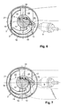
- a reciprocating piston 2 is arranged in a cylinder 1.
- the surface 3 of the Piston 2 forms together with the roof-shaped combustion chamber top surface in cylinder head 4 5 a combustion chamber 6, into which an ignition device 8 opens.
- the Mouth 10 of a fuel introduction device 9 is located at the edge of the combustion chamber 6.
- the longitudinal axis of the fuel delivery device 9 is designated 11, the Angle y between the longitudinal axis 1 1 and the plane of the cylinder head 4 is 25 to 60 °.
- the fuel introduction device 9 is arranged so that an injected fuel jet 12 is essentially directed towards the ignition device 8, and the fuel jet 12 approximately in the area of the combustion chamber trough 14 of the piston 2 strikes its surface 3.
- a reference plane ⁇ is introduced, which through the intersection of the two roof-shaped boundary surfaces of the Combustion chamber 6 and the piston axis 7 is spanned. (see Fig. 1 and Fig. 3).
- the swirl movement is on the piston surface 3 the asymmetrical, arch-shaped guide rib 13 supporting the cylinder charge is formed, which largely the roof-shaped boundary of the combustion chamber 6 in its outer contour is reproduced, and the essentially centrally shaped combustion chamber trough 14 and one Has trough inlet 15 located in the area of the fuel introduction device 9.
- the guide rib 13 has the direction of the swirl flow designated by 16 (see, for example, FIG. 3) end 17 tapering in width and height.
- the invention has the following features: Trough diameter D m 0.3 * D ⁇ D m ⁇ 0.6 * D Depth of the trough T m 0.1 * D ⁇ T m ⁇ 0.23 * D Depth below the crushing surface T uq 0.02 * D ⁇ T uq ⁇ 0.14 * D Width of the guide rib B 0.06 * D ⁇ B ⁇ 0.15 * D Eccentricity E -0.03 * D ⁇ E ⁇ + 0.12 * D Eccentricity E h -0.12 * D ⁇ E h ⁇ 0.12 * D Beginning of the ribs 20 ° ⁇ ⁇ 70 ° Guide rib end 120 ° ⁇ ⁇ 170 ° Inclination of the flow control surface -5 ° ⁇ ⁇ 20 °
- the data on the eccentricity refer to the center of gravity z of the combustion chamber bowl 14 in the plane of the piston surface 3.
- the combustion chamber trough 14 can also be in the be substantially circular.
- D is the piston diameter.
- the angle information in connection with the beginning 25 and the end 17 of the Guide ribs 13 are made clockwise around the piston axis, starting from the reference plane ⁇ 7 measured.
- the inner flow guide surface 13 ', which delimits the combustion chamber trough, can be inclined outwards ( ⁇ ⁇ 5 °) or inwards ( ⁇ ⁇ 20 °).
- the invention can be advantageous in terms of design variants with two, three, four or five valves per cylinder.
Landscapes
- Engineering & Computer Science (AREA)
- Chemical & Material Sciences (AREA)
- Combustion & Propulsion (AREA)
- Mechanical Engineering (AREA)
- General Engineering & Computer Science (AREA)
- Combustion Methods Of Internal-Combustion Engines (AREA)
Applications Claiming Priority (3)
| Application Number | Priority Date | Filing Date | Title |
|---|---|---|---|
| AT532/97 | 1997-03-27 | ||
| AT53297 | 1997-03-27 | ||
| AT0053297U AT2378U1 (de) | 1997-08-28 | 1997-08-28 | Brennkraftmaschine mit fremdzündung |
Publications (3)
| Publication Number | Publication Date |
|---|---|
| EP0899432A2 true EP0899432A2 (fr) | 1999-03-03 |
| EP0899432A3 EP0899432A3 (fr) | 1999-12-22 |
| EP0899432B1 EP0899432B1 (fr) | 2002-12-11 |
Family
ID=3493123
Family Applications (1)
| Application Number | Title | Priority Date | Filing Date |
|---|---|---|---|
| EP98890231A Expired - Lifetime EP0899432B1 (fr) | 1997-08-28 | 1998-08-06 | Moteur à combustion interne à allumage par étincelle |
Country Status (5)
| Country | Link |
|---|---|
| US (1) | US5979399A (fr) |
| EP (1) | EP0899432B1 (fr) |
| JP (1) | JP3079427B2 (fr) |
| AT (2) | AT2378U1 (fr) |
| DE (1) | DE59806601D1 (fr) |
Cited By (1)
| Publication number | Priority date | Publication date | Assignee | Title |
|---|---|---|---|---|
| DE19726683B4 (de) * | 1997-06-24 | 2009-03-19 | Iav Gmbh Ingenieurgesellschaft Auto Und Verkehr | Mehrzylinder-Ottomotor mit Kraftstoffeinspritzung in den Brennraum und ein Verfahren zum Betreiben desselben |
Families Citing this family (24)
| Publication number | Priority date | Publication date | Assignee | Title |
|---|---|---|---|---|
| EP1739294A1 (fr) * | 1997-05-20 | 2007-01-03 | Nissan Motor Co., Ltd. | Piston pour moteur à essence à injection directe |
| US6223715B1 (en) * | 1998-03-23 | 2001-05-01 | Yamaha Hatsudoki Kabushiki Kaisha | Combustion chamber for direct injected engine |
| GB9821052D0 (en) * | 1998-09-28 | 1998-11-18 | Ricardo Consulting Eng | Direct injection gasoline engines |
| AT3751U1 (de) * | 1999-08-26 | 2000-07-25 | Avl List Gmbh | Brennkraftmaschine mit fremdzündung |
| DE10018777B4 (de) | 2000-04-15 | 2018-05-30 | Dr. Ing. H.C. F. Porsche Aktiengesellschaft | Brennkraftmaschine der Ottobauart mit Direkteinspritzung |
| JP2002327622A (ja) * | 2001-04-27 | 2002-11-15 | Unisia Jecs Corp | 内燃機関のピストン |
| JPWO2003029635A1 (ja) * | 2001-09-17 | 2005-01-20 | 日産自動車株式会社 | 内燃機関の成層混合気形成装置及び方法 |
| JP3931752B2 (ja) * | 2002-07-12 | 2007-06-20 | トヨタ自動車株式会社 | 混合気を圧縮自着火させる内燃機関、および内燃機関の制御方法 |
| US20050183693A1 (en) * | 2004-02-25 | 2005-08-25 | Ford Global Technologies Llc | Method and apparatus for controlling operation of dual mode hcci engines |
| DE102004053049A1 (de) * | 2004-11-03 | 2006-05-04 | Daimlerchrysler Ag | Brennkraftmaschine mit Direkteinspritzung |
| US7240645B2 (en) * | 2005-10-28 | 2007-07-10 | Reisser Heinz-Gustav A | Internal combustion engine |
| US7647907B2 (en) | 2006-12-07 | 2010-01-19 | Contour Hardening, Inc. | Induction driven ignition system |
| US8424501B2 (en) * | 2006-12-07 | 2013-04-23 | Contour Hardening, Inc. | Induction driven ignition system |
| US7533643B2 (en) * | 2006-12-07 | 2009-05-19 | Contour Hardening, Inc. | Induction driven ignition system |
| KR20100049934A (ko) * | 2008-11-04 | 2010-05-13 | 현대자동차주식회사 | 가솔린 직접 분사 엔진 |
| DE102009026574A1 (de) * | 2009-05-29 | 2010-12-02 | Robert Bosch Gmbh | Brennkraftmaschine, insbesondere Gasmotor, mit Laserzündeinrichtung |
| KR101373805B1 (ko) * | 2009-11-26 | 2014-03-12 | 기아자동차주식회사 | 가솔린 직접 분사 엔진 |
| US9091199B2 (en) * | 2013-02-26 | 2015-07-28 | GM Global Technology Operations LLC | Combustion system for an engine having a swirl inducing combustion chamber |
| JP6264882B2 (ja) * | 2013-12-26 | 2018-01-24 | トヨタ自動車株式会社 | 火花点火式内燃機関の燃焼室構造 |
| JP2015124659A (ja) * | 2013-12-26 | 2015-07-06 | トヨタ自動車株式会社 | 火花点火式内燃機関の燃焼室構造 |
| US10422299B2 (en) * | 2016-04-21 | 2019-09-24 | Tenneco Inc. | Piston with asymmetric upper combustion surface and method of manufacture thereof |
| US9995203B2 (en) * | 2016-10-27 | 2018-06-12 | Caterpillar Inc. | Piston design for flow re-direction |
| CN108915646A (zh) * | 2018-09-06 | 2018-11-30 | 李龙龙 | 输气管线多相流排水采气工具 |
| JP7180304B2 (ja) * | 2018-11-16 | 2022-11-30 | マツダ株式会社 | エンジンの燃焼室構造 |
Family Cites Families (11)
| Publication number | Priority date | Publication date | Assignee | Title |
|---|---|---|---|---|
| DE649738C (de) * | 1935-03-06 | 1937-09-04 | Alfred Buechi | Viertaktbrennkraftmaschine mit Schiebersteuerung |
| DE1576001A1 (de) * | 1967-01-14 | 1970-05-21 | Daimler Benz Ag | Fremdgezuendete Einspritzbrennkraftmaschine mit Schichtladung |
| FR2421276A1 (fr) * | 1978-03-31 | 1979-10-26 | Chrysler France | Moteur a combustion interne a chambre principale de combustion et chambre de turbulence |
| JPS58501332A (ja) * | 1981-08-13 | 1983-08-11 | マツセイ−フア−ガソン−パ−キンス リミテツド | 内燃機関 |
| US4446830A (en) * | 1983-01-10 | 1984-05-08 | Ford Motor Company | Method of operating an engine with a high heat of vaporization fuel |
| US4719884A (en) * | 1986-02-03 | 1988-01-19 | Kubota Ltd. | Combustion chamber with a domed auxiliary chamber for a spark-ignition engine |
| US5140958A (en) * | 1990-06-27 | 1992-08-25 | Toyota Jidosha Kabushiki Kaisha | Two-stroke engine |
| JPH07102976A (ja) * | 1993-10-05 | 1995-04-18 | Toyota Motor Corp | 筒内噴射式火花点火機関 |
| US5775288A (en) * | 1995-08-17 | 1998-07-07 | Yamaha Hatsudoki Kabushiki Kaisha | Combustion chamber |
| AT1392U1 (de) * | 1996-05-30 | 1997-04-25 | Avl Verbrennungskraft Messtech | Brennkraftmaschine mit fremdzündung |
| JP3746344B2 (ja) * | 1996-12-24 | 2006-02-15 | トヨタ自動車株式会社 | 内燃機関の燃焼室構造 |
-
1997
- 1997-08-28 AT AT0053297U patent/AT2378U1/de not_active IP Right Cessation
-
1998
- 1998-08-06 EP EP98890231A patent/EP0899432B1/fr not_active Expired - Lifetime
- 1998-08-06 AT AT98890231T patent/ATE229616T1/de not_active IP Right Cessation
- 1998-08-06 DE DE59806601T patent/DE59806601D1/de not_active Expired - Lifetime
- 1998-08-27 US US09/141,315 patent/US5979399A/en not_active Expired - Fee Related
- 1998-08-28 JP JP10242388A patent/JP3079427B2/ja not_active Expired - Fee Related
Cited By (1)
| Publication number | Priority date | Publication date | Assignee | Title |
|---|---|---|---|---|
| DE19726683B4 (de) * | 1997-06-24 | 2009-03-19 | Iav Gmbh Ingenieurgesellschaft Auto Und Verkehr | Mehrzylinder-Ottomotor mit Kraftstoffeinspritzung in den Brennraum und ein Verfahren zum Betreiben desselben |
Also Published As
| Publication number | Publication date |
|---|---|
| US5979399A (en) | 1999-11-09 |
| EP0899432A3 (fr) | 1999-12-22 |
| DE59806601D1 (de) | 2003-01-23 |
| JP3079427B2 (ja) | 2000-08-21 |
| EP0899432B1 (fr) | 2002-12-11 |
| ATE229616T1 (de) | 2002-12-15 |
| JPH11141399A (ja) | 1999-05-25 |
| AT2378U1 (de) | 1998-09-25 |
Similar Documents
| Publication | Publication Date | Title |
|---|---|---|
| EP0899432B1 (fr) | Moteur à combustion interne à allumage par étincelle | |
| DE19713028C2 (de) | Viertakt-Brennkraftmaschine mit Fremdzündung | |
| DE19713030C2 (de) | Viertakt-Brennkraftmaschine mit Fremdzündung | |
| DE19713029C2 (de) | Viertakt-Brennkraftmaschine mit Fremdzündung | |
| DE69717050T2 (de) | Brennkammer | |
| DE19804161C2 (de) | Viertakt-Brennkraftmaschine | |
| DE10124750A1 (de) | Brennstoffeinspritzsystem | |
| EP1319822B9 (fr) | Moteur à combustion avec injection directe | |
| EP0909885B1 (fr) | Moteur à combustion à allumage commandé | |
| EP0897052B1 (fr) | Moteur à combustion interne à allumage par étincelle | |
| EP1362996B1 (fr) | Piston pour un moteur à combustion interne à injection directe, à allumage par etincelle | |
| EP0741237B1 (fr) | Moteur à combustion à allumage commandé | |
| DE69008131T2 (de) | Brennkraftmaschine. | |
| DE10041424C2 (de) | Brennkraftmaschine mit Fremdzündung | |
| DE10354827A1 (de) | Brennstoffeinspritzsystem | |
| DE19838868C2 (de) | Brennkraftmaschine mit Fremdzündung | |
| DE19621635A1 (de) | Diesel-Brennkraftmaschine | |
| WO2004059154A1 (fr) | Machine a combustion interne avec autoallumage | |
| AT1392U1 (de) | Brennkraftmaschine mit fremdzündung | |
| DE10027452C2 (de) | Verfahren zur Gemischbildung mit Prallunterstützung in Brennkraftmaschinen mit Benzin-Direkteinspritzung | |
| DE10106887A1 (de) | Direkteinspritzende Brennkraftmaschine mit Fremdzündung und Verfahren zum Betrieb einer derartigen Brennkraftmaschine | |
| DE4033822C2 (de) | Brennraum eines Dieselmotors mit Direkteinspritzung | |
| EP0881372B1 (fr) | Moteur à quatre temps à allumage commandé et à injection directe | |
| AT1562U1 (de) | Viertakt-brennkraftmaschine mit fremdzündung | |
| AT1564U1 (de) | Viertakt-brennkraftmaschine mit fremdzündung |
Legal Events
| Date | Code | Title | Description |
|---|---|---|---|
| PUAI | Public reference made under article 153(3) epc to a published international application that has entered the european phase |
Free format text: ORIGINAL CODE: 0009012 |
|
| AK | Designated contracting states |
Kind code of ref document: A2 Designated state(s): AT DE ES FR GB IT SE |
|
| AX | Request for extension of the european patent |
Free format text: AL;LT;LV;MK;RO;SI |
|
| PUAL | Search report despatched |
Free format text: ORIGINAL CODE: 0009013 |
|
| AK | Designated contracting states |
Kind code of ref document: A3 Designated state(s): AT BE CH CY DE DK ES FI FR GB GR IE IT LI LU MC NL PT SE |
|
| AX | Request for extension of the european patent |
Free format text: AL;LT;LV;MK;RO;SI |
|
| 17P | Request for examination filed |
Effective date: 20000114 |
|
| AKX | Designation fees paid |
Free format text: AT DE ES FR GB IT SE |
|
| GRAG | Despatch of communication of intention to grant |
Free format text: ORIGINAL CODE: EPIDOS AGRA |
|
| GRAG | Despatch of communication of intention to grant |
Free format text: ORIGINAL CODE: EPIDOS AGRA |
|
| GRAH | Despatch of communication of intention to grant a patent |
Free format text: ORIGINAL CODE: EPIDOS IGRA |
|
| 17Q | First examination report despatched |
Effective date: 20020603 |
|
| GRAH | Despatch of communication of intention to grant a patent |
Free format text: ORIGINAL CODE: EPIDOS IGRA |
|
| GRAA | (expected) grant |
Free format text: ORIGINAL CODE: 0009210 |
|
| AK | Designated contracting states |
Kind code of ref document: B1 Designated state(s): AT DE ES FR GB IT SE |
|
| PG25 | Lapsed in a contracting state [announced via postgrant information from national office to epo] |
Ref country code: GB Free format text: LAPSE BECAUSE OF FAILURE TO SUBMIT A TRANSLATION OF THE DESCRIPTION OR TO PAY THE FEE WITHIN THE PRESCRIBED TIME-LIMIT Effective date: 20021211 |
|
| REF | Corresponds to: |
Ref document number: 229616 Country of ref document: AT Date of ref document: 20021215 Kind code of ref document: T |
|
| REG | Reference to a national code |
Ref country code: GB Ref legal event code: FG4D Free format text: NOT ENGLISH |
|
| REF | Corresponds to: |
Ref document number: 59806601 Country of ref document: DE Date of ref document: 20030123 |
|
| PG25 | Lapsed in a contracting state [announced via postgrant information from national office to epo] |
Ref country code: SE Free format text: LAPSE BECAUSE OF FAILURE TO SUBMIT A TRANSLATION OF THE DESCRIPTION OR TO PAY THE FEE WITHIN THE PRESCRIBED TIME-LIMIT Effective date: 20030311 |
|
| GBV | Gb: ep patent (uk) treated as always having been void in accordance with gb section 77(7)/1977 [no translation filed] |
Effective date: 20021211 |
|
| PG25 | Lapsed in a contracting state [announced via postgrant information from national office to epo] |
Ref country code: ES Free format text: LAPSE BECAUSE OF FAILURE TO SUBMIT A TRANSLATION OF THE DESCRIPTION OR TO PAY THE FEE WITHIN THE PRESCRIBED TIME-LIMIT Effective date: 20030627 |
|
| PG25 | Lapsed in a contracting state [announced via postgrant information from national office to epo] |
Ref country code: AT Free format text: LAPSE BECAUSE OF NON-PAYMENT OF DUE FEES Effective date: 20030806 |
|
| ET | Fr: translation filed | ||
| PLBE | No opposition filed within time limit |
Free format text: ORIGINAL CODE: 0009261 |
|
| STAA | Information on the status of an ep patent application or granted ep patent |
Free format text: STATUS: NO OPPOSITION FILED WITHIN TIME LIMIT |
|
| 26N | No opposition filed |
Effective date: 20030912 |
|
| PGFP | Annual fee paid to national office [announced via postgrant information from national office to epo] |
Ref country code: IT Payment date: 20080826 Year of fee payment: 11 Ref country code: FR Payment date: 20080828 Year of fee payment: 11 |
|
| REG | Reference to a national code |
Ref country code: FR Ref legal event code: ST Effective date: 20100430 |
|
| PG25 | Lapsed in a contracting state [announced via postgrant information from national office to epo] |
Ref country code: FR Free format text: LAPSE BECAUSE OF NON-PAYMENT OF DUE FEES Effective date: 20090831 |
|
| PG25 | Lapsed in a contracting state [announced via postgrant information from national office to epo] |
Ref country code: IT Free format text: LAPSE BECAUSE OF NON-PAYMENT OF DUE FEES Effective date: 20090806 |
|
| PGFP | Annual fee paid to national office [announced via postgrant information from national office to epo] |
Ref country code: DE Payment date: 20131002 Year of fee payment: 16 |
|
| REG | Reference to a national code |
Ref country code: DE Ref legal event code: R119 Ref document number: 59806601 Country of ref document: DE |
|
| REG | Reference to a national code |
Ref country code: DE Ref legal event code: R119 Ref document number: 59806601 Country of ref document: DE Effective date: 20150303 |
|
| PG25 | Lapsed in a contracting state [announced via postgrant information from national office to epo] |
Ref country code: DE Free format text: LAPSE BECAUSE OF NON-PAYMENT OF DUE FEES Effective date: 20150303 |