JP7180304B2 - エンジンの燃焼室構造 - Google Patents
エンジンの燃焼室構造 Download PDFInfo
- Publication number
- JP7180304B2 JP7180304B2 JP2018215642A JP2018215642A JP7180304B2 JP 7180304 B2 JP7180304 B2 JP 7180304B2 JP 2018215642 A JP2018215642 A JP 2018215642A JP 2018215642 A JP2018215642 A JP 2018215642A JP 7180304 B2 JP7180304 B2 JP 7180304B2
- Authority
- JP
- Japan
- Prior art keywords
- combustion
- combustion chamber
- cavity
- engine
- intake
- Prior art date
- Legal status (The legal status is an assumption and is not a legal conclusion. Google has not performed a legal analysis and makes no representation as to the accuracy of the status listed.)
- Active
Links
- 238000002485 combustion reaction Methods 0.000 title claims description 285
- 230000002093 peripheral effect Effects 0.000 claims description 111
- 230000006835 compression Effects 0.000 claims description 89
- 238000007906 compression Methods 0.000 claims description 89
- 239000000446 fuel Substances 0.000 claims description 89
- 239000000203 mixture Substances 0.000 claims description 39
- 230000000630 rising effect Effects 0.000 claims description 9
- 238000002347 injection Methods 0.000 description 38
- 239000007924 injection Substances 0.000 description 38
- 238000010586 diagram Methods 0.000 description 26
- 239000007789 gas Substances 0.000 description 16
- 230000000694 effects Effects 0.000 description 15
- 238000012423 maintenance Methods 0.000 description 12
- 238000011144 upstream manufacturing Methods 0.000 description 9
- 230000003197 catalytic effect Effects 0.000 description 7
- 239000003054 catalyst Substances 0.000 description 6
- 230000007423 decrease Effects 0.000 description 6
- 230000033001 locomotion Effects 0.000 description 6
- XLYOFNOQVPJJNP-UHFFFAOYSA-N water Substances O XLYOFNOQVPJJNP-UHFFFAOYSA-N 0.000 description 5
- 230000015572 biosynthetic process Effects 0.000 description 4
- 239000002828 fuel tank Substances 0.000 description 4
- 239000003502 gasoline Substances 0.000 description 4
- 230000007246 mechanism Effects 0.000 description 4
- QVGXLLKOCUKJST-UHFFFAOYSA-N atomic oxygen Chemical compound [O] QVGXLLKOCUKJST-UHFFFAOYSA-N 0.000 description 3
- 239000001301 oxygen Substances 0.000 description 3
- 229910052760 oxygen Inorganic materials 0.000 description 3
- 230000008859 change Effects 0.000 description 2
- 238000001514 detection method Methods 0.000 description 2
- 230000001737 promoting effect Effects 0.000 description 2
- 238000010926 purge Methods 0.000 description 2
- 238000013517 stratification Methods 0.000 description 2
- 230000001960 triggered effect Effects 0.000 description 2
- 230000005540 biological transmission Effects 0.000 description 1
- 239000000498 cooling water Substances 0.000 description 1
- 238000013461 design Methods 0.000 description 1
- 230000006866 deterioration Effects 0.000 description 1
- 230000002708 enhancing effect Effects 0.000 description 1
- 238000011156 evaluation Methods 0.000 description 1
- 230000020169 heat generation Effects 0.000 description 1
- 229930195733 hydrocarbon Natural products 0.000 description 1
- 150000002430 hydrocarbons Chemical class 0.000 description 1
- 238000009434 installation Methods 0.000 description 1
- 239000013067 intermediate product Substances 0.000 description 1
- 238000012986 modification Methods 0.000 description 1
- 230000004048 modification Effects 0.000 description 1
- 239000013618 particulate matter Substances 0.000 description 1
- 238000012545 processing Methods 0.000 description 1
- 230000004044 response Effects 0.000 description 1
- 239000004071 soot Substances 0.000 description 1
- 239000007921 spray Substances 0.000 description 1
- 230000004083 survival effect Effects 0.000 description 1
Images


Classifications
-
- F—MECHANICAL ENGINEERING; LIGHTING; HEATING; WEAPONS; BLASTING
- F02—COMBUSTION ENGINES; HOT-GAS OR COMBUSTION-PRODUCT ENGINE PLANTS
- F02B—INTERNAL-COMBUSTION PISTON ENGINES; COMBUSTION ENGINES IN GENERAL
- F02B23/00—Other engines characterised by special shape or construction of combustion chambers to improve operation
- F02B23/02—Other engines characterised by special shape or construction of combustion chambers to improve operation with compression ignition
- F02B23/06—Other engines characterised by special shape or construction of combustion chambers to improve operation with compression ignition the combustion space being arranged in working piston
- F02B23/0618—Other engines characterised by special shape or construction of combustion chambers to improve operation with compression ignition the combustion space being arranged in working piston having in-cylinder means to influence the charge motion
- F02B23/0624—Swirl flow
-
- F—MECHANICAL ENGINEERING; LIGHTING; HEATING; WEAPONS; BLASTING
- F02—COMBUSTION ENGINES; HOT-GAS OR COMBUSTION-PRODUCT ENGINE PLANTS
- F02B—INTERNAL-COMBUSTION PISTON ENGINES; COMBUSTION ENGINES IN GENERAL
- F02B11/00—Engines characterised by both fuel-air mixture compression and air compression, or characterised by both positive ignition and compression ignition, e.g. in different cylinders
-
- F—MECHANICAL ENGINEERING; LIGHTING; HEATING; WEAPONS; BLASTING
- F02—COMBUSTION ENGINES; HOT-GAS OR COMBUSTION-PRODUCT ENGINE PLANTS
- F02B—INTERNAL-COMBUSTION PISTON ENGINES; COMBUSTION ENGINES IN GENERAL
- F02B23/00—Other engines characterised by special shape or construction of combustion chambers to improve operation
- F02B23/02—Other engines characterised by special shape or construction of combustion chambers to improve operation with compression ignition
- F02B23/06—Other engines characterised by special shape or construction of combustion chambers to improve operation with compression ignition the combustion space being arranged in working piston
- F02B23/0678—Unconventional, complex or non-rotationally symmetrical shapes of the combustion space, e.g. flower like, having special shapes related to the orientation of the fuel spray jets
-
- F—MECHANICAL ENGINEERING; LIGHTING; HEATING; WEAPONS; BLASTING
- F02—COMBUSTION ENGINES; HOT-GAS OR COMBUSTION-PRODUCT ENGINE PLANTS
- F02B—INTERNAL-COMBUSTION PISTON ENGINES; COMBUSTION ENGINES IN GENERAL
- F02B23/00—Other engines characterised by special shape or construction of combustion chambers to improve operation
- F02B23/08—Other engines characterised by special shape or construction of combustion chambers to improve operation with positive ignition
- F02B23/10—Other engines characterised by special shape or construction of combustion chambers to improve operation with positive ignition with separate admission of air and fuel into cylinder
- F02B23/101—Other engines characterised by special shape or construction of combustion chambers to improve operation with positive ignition with separate admission of air and fuel into cylinder the injector being placed on or close to the cylinder centre axis, e.g. with mixture formation using spray guided concepts
-
- F—MECHANICAL ENGINEERING; LIGHTING; HEATING; WEAPONS; BLASTING
- F02—COMBUSTION ENGINES; HOT-GAS OR COMBUSTION-PRODUCT ENGINE PLANTS
- F02D—CONTROLLING COMBUSTION ENGINES
- F02D41/00—Electrical control of supply of combustible mixture or its constituents
- F02D41/30—Controlling fuel injection
- F02D41/3011—Controlling fuel injection according to or using specific or several modes of combustion
- F02D41/3017—Controlling fuel injection according to or using specific or several modes of combustion characterised by the mode(s) being used
- F02D41/3035—Controlling fuel injection according to or using specific or several modes of combustion characterised by the mode(s) being used a mode being the premixed charge compression-ignition mode
- F02D41/3041—Controlling fuel injection according to or using specific or several modes of combustion characterised by the mode(s) being used a mode being the premixed charge compression-ignition mode with means for triggering compression ignition, e.g. spark plug
-
- F—MECHANICAL ENGINEERING; LIGHTING; HEATING; WEAPONS; BLASTING
- F02—COMBUSTION ENGINES; HOT-GAS OR COMBUSTION-PRODUCT ENGINE PLANTS
- F02D—CONTROLLING COMBUSTION ENGINES
- F02D41/00—Electrical control of supply of combustible mixture or its constituents
- F02D41/30—Controlling fuel injection
- F02D41/38—Controlling fuel injection of the high pressure type
- F02D41/40—Controlling fuel injection of the high pressure type with means for controlling injection timing or duration
- F02D41/402—Multiple injections
-
- F—MECHANICAL ENGINEERING; LIGHTING; HEATING; WEAPONS; BLASTING
- F02—COMBUSTION ENGINES; HOT-GAS OR COMBUSTION-PRODUCT ENGINE PLANTS
- F02B—INTERNAL-COMBUSTION PISTON ENGINES; COMBUSTION ENGINES IN GENERAL
- F02B23/00—Other engines characterised by special shape or construction of combustion chambers to improve operation
- F02B23/08—Other engines characterised by special shape or construction of combustion chambers to improve operation with positive ignition
- F02B23/10—Other engines characterised by special shape or construction of combustion chambers to improve operation with positive ignition with separate admission of air and fuel into cylinder
- F02B2023/106—Tumble flow, i.e. the axis of rotation of the main charge flow motion is horizontal
-
- F—MECHANICAL ENGINEERING; LIGHTING; HEATING; WEAPONS; BLASTING
- F02—COMBUSTION ENGINES; HOT-GAS OR COMBUSTION-PRODUCT ENGINE PLANTS
- F02B—INTERNAL-COMBUSTION PISTON ENGINES; COMBUSTION ENGINES IN GENERAL
- F02B23/00—Other engines characterised by special shape or construction of combustion chambers to improve operation
- F02B23/08—Other engines characterised by special shape or construction of combustion chambers to improve operation with positive ignition
- F02B23/10—Other engines characterised by special shape or construction of combustion chambers to improve operation with positive ignition with separate admission of air and fuel into cylinder
- F02B2023/108—Swirl flow, i.e. the axis of rotation of the main charge flow motion is vertical
-
- F—MECHANICAL ENGINEERING; LIGHTING; HEATING; WEAPONS; BLASTING
- F02—COMBUSTION ENGINES; HOT-GAS OR COMBUSTION-PRODUCT ENGINE PLANTS
- F02B—INTERNAL-COMBUSTION PISTON ENGINES; COMBUSTION ENGINES IN GENERAL
- F02B23/00—Other engines characterised by special shape or construction of combustion chambers to improve operation
- F02B23/02—Other engines characterised by special shape or construction of combustion chambers to improve operation with compression ignition
- F02B23/06—Other engines characterised by special shape or construction of combustion chambers to improve operation with compression ignition the combustion space being arranged in working piston
- F02B23/0618—Other engines characterised by special shape or construction of combustion chambers to improve operation with compression ignition the combustion space being arranged in working piston having in-cylinder means to influence the charge motion
- F02B23/063—Other engines characterised by special shape or construction of combustion chambers to improve operation with compression ignition the combustion space being arranged in working piston having in-cylinder means to influence the charge motion the combustion space in the piston interacting fluid dynamically with the cylinder head, the injector body or the cylinder wall
-
- F—MECHANICAL ENGINEERING; LIGHTING; HEATING; WEAPONS; BLASTING
- F02—COMBUSTION ENGINES; HOT-GAS OR COMBUSTION-PRODUCT ENGINE PLANTS
- F02B—INTERNAL-COMBUSTION PISTON ENGINES; COMBUSTION ENGINES IN GENERAL
- F02B23/00—Other engines characterised by special shape or construction of combustion chambers to improve operation
- F02B23/02—Other engines characterised by special shape or construction of combustion chambers to improve operation with compression ignition
- F02B23/06—Other engines characterised by special shape or construction of combustion chambers to improve operation with compression ignition the combustion space being arranged in working piston
- F02B23/0642—Other engines characterised by special shape or construction of combustion chambers to improve operation with compression ignition the combustion space being arranged in working piston the depth of the combustion space being much smaller than the diameter of the piston, e.g. the depth being in the order of one tenth of the diameter
-
- F—MECHANICAL ENGINEERING; LIGHTING; HEATING; WEAPONS; BLASTING
- F02—COMBUSTION ENGINES; HOT-GAS OR COMBUSTION-PRODUCT ENGINE PLANTS
- F02D—CONTROLLING COMBUSTION ENGINES
- F02D41/00—Electrical control of supply of combustible mixture or its constituents
- F02D41/0002—Controlling intake air
- F02D2041/0015—Controlling intake air for engines with means for controlling swirl or tumble flow, e.g. by using swirl valves
-
- F—MECHANICAL ENGINEERING; LIGHTING; HEATING; WEAPONS; BLASTING
- F02—COMBUSTION ENGINES; HOT-GAS OR COMBUSTION-PRODUCT ENGINE PLANTS
- F02P—IGNITION, OTHER THAN COMPRESSION IGNITION, FOR INTERNAL-COMBUSTION ENGINES; TESTING OF IGNITION TIMING IN COMPRESSION-IGNITION ENGINES
- F02P15/00—Electric spark ignition having characteristics not provided for in, or of interest apart from, groups F02P1/00 - F02P13/00 and combined with layout of ignition circuits
- F02P15/08—Electric spark ignition having characteristics not provided for in, or of interest apart from, groups F02P1/00 - F02P13/00 and combined with layout of ignition circuits having multiple-spark ignition, i.e. ignition occurring simultaneously at different places in one engine cylinder or in two or more separate engine cylinders
-
- Y—GENERAL TAGGING OF NEW TECHNOLOGICAL DEVELOPMENTS; GENERAL TAGGING OF CROSS-SECTIONAL TECHNOLOGIES SPANNING OVER SEVERAL SECTIONS OF THE IPC; TECHNICAL SUBJECTS COVERED BY FORMER USPC CROSS-REFERENCE ART COLLECTIONS [XRACs] AND DIGESTS
- Y02—TECHNOLOGIES OR APPLICATIONS FOR MITIGATION OR ADAPTATION AGAINST CLIMATE CHANGE
- Y02T—CLIMATE CHANGE MITIGATION TECHNOLOGIES RELATED TO TRANSPORTATION
- Y02T10/00—Road transport of goods or passengers
- Y02T10/10—Internal combustion engine [ICE] based vehicles
- Y02T10/12—Improving ICE efficiencies
-
- Y—GENERAL TAGGING OF NEW TECHNOLOGICAL DEVELOPMENTS; GENERAL TAGGING OF CROSS-SECTIONAL TECHNOLOGIES SPANNING OVER SEVERAL SECTIONS OF THE IPC; TECHNICAL SUBJECTS COVERED BY FORMER USPC CROSS-REFERENCE ART COLLECTIONS [XRACs] AND DIGESTS
- Y02—TECHNOLOGIES OR APPLICATIONS FOR MITIGATION OR ADAPTATION AGAINST CLIMATE CHANGE
- Y02T—CLIMATE CHANGE MITIGATION TECHNOLOGIES RELATED TO TRANSPORTATION
- Y02T10/00—Road transport of goods or passengers
- Y02T10/10—Internal combustion engine [ICE] based vehicles
- Y02T10/40—Engine management systems
Landscapes
- Engineering & Computer Science (AREA)
- Chemical & Material Sciences (AREA)
- Combustion & Propulsion (AREA)
- Mechanical Engineering (AREA)
- General Engineering & Computer Science (AREA)
- Physics & Mathematics (AREA)
- Fluid Mechanics (AREA)
- Combustion Methods Of Internal-Combustion Engines (AREA)
- Pistons, Piston Rings, And Cylinders (AREA)
Description
以下、図面に基づいて、本発明の実施形態について詳細に説明する。先ず、図1に示すシステム図を参照して、本発明に係る燃焼室構造が適用された部分圧縮着火式エンジン(以下、単にエンジンという)の全体構成を説明する。図1に示されるエンジンは、走行用の動力源として車両に搭載された4サイクルのガソリン直噴エンジンであり、エンジン本体1と、エンジン本体1に導入される吸気が流通する吸気通路30と、エンジン本体1から排出される排気ガスが流通する排気通路40と、排気通路40を流通する排気ガスの一部を吸気通路30に還流する外部EGR装置45と、エンジン本体1にガソリンを主成分とする燃料を供給するフューエルシステム150と、を備えている。
続いて、上述したエンジンの制御系統について説明する。図4は、エンジンの制御系統を示すブロック図である。制御系統はECU20を備える。ECU20は、エンジンを統括的に制御するためのマイクロプロセッサであり、周知のCPU、ROM、RAM等から構成されている。
図5は、本実施形態のエンジンの温間時に使用される運転マップであり、エンジンの回転速度/負荷に応じた制御の相違を示す図である。なお、以下の説明において、エンジンの負荷が高い(低い)とは、エンジンの要求トルクが高い(低い)ことと等価である。
低・中速/低負荷の第1運転領域A1では、SI燃焼とCI燃焼とを組み合わせた部分圧縮着火燃焼(以下、これをSPCCI燃焼という)が実行される。SI燃焼とは、点火プラグ16から発生する火花により混合気に点火し、その点火点からその周囲へと燃焼領域を拡げていく火炎伝播により混合気を強制的に燃焼させる燃焼形態のことである。CI燃焼とは、ピストン5の圧縮により高温・高圧化された環境下で、混合気を自着火により燃焼させる燃焼形態のことである。これらSI燃焼とCI燃焼とを組み合わせたSPCCI燃焼とは、混合気が自着火する寸前の環境下で行われる火花点火により燃焼室6内の混合気の一部をSI燃焼させ、このSI燃焼の後に(当該SI燃焼に伴うさらなる高温・高圧化によって)、燃焼室6内の他の混合気を自着火によりCI燃焼させる燃焼形態である。なお、「SPCCI」は「Spark Controlled Compression Ignition」の略である。
低・中速/高負荷の第2運転領域A2では、1回の火花点火によって混合気をSPCCI燃焼させる制御が実行される。換言すると、第2運転領域A2では、上述した第1運転領域A1における先行点火が省略されて、主点火のみが実行される。このような1回点火によるSPCCI燃焼を実現するため、第2運転領域A2では、ECU20の全体制御部27によってエンジンの各部が次のように制御される。
上記第1・第2運転領域A1,A2よりも高速側の第3運転領域A3では、SI燃焼が実行される。このSI燃焼の実現のために、第3運転領域A3では、全体制御部27によってエンジンの各部が次のように制御される。
本実施形態の燃焼室6内では、筒内流動として、少なくともタンブル流とスワール流とが発生する。すなわち、上記で説明した通り、本実施形態の吸気ポート9(9A、9B)は、タンブル流を形成可能なタンブルポートである。また、スワール弁17の開閉により、スワール流を形成することができる。本実施形態のエンジンは、SI燃焼とSPCCI燃焼とが併用されるが、前者の燃焼態様ではタンブル流が肝要となり、後者の燃焼態様ではスワール流が肝要となる。
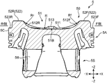
続いて、図8~図11を参照して、ピストン5の構造、とりわけ冠面50の構造について詳細に説明する。本実施形態では、冠面50に、上述したタンブル流及びスワール流の双方を圧縮上死点付近まで維持させることを可能とする形状的工夫が施されている。図8は、図1及び図2に示されたピストン5の斜視図、図9は、冠面50の平面図、図10は、図9のX-X線断面図、図11は、図9のXI-XI線断面図である。図8~図11では、説明の明確性を担保するため、XYZの方向表示を付している。Z方向は気筒軸AX方向、X方向はクランク軸7の延伸方向であるエンジン本体1の前後方向、Y方向はZ方向及びX方向の双方と直交する方向に各々相当する。各図には、エンジン本体1の設置方向におけるフロント側、リア側という意味においてF側(+X側)、R側(-X側)と、吸気ポート9及び排気ポート10と各々対向する側であるという意味においてIN側(+Y側)、EX側(-Y側)との表記が付されている。
図12は、キャビティ51に関連する各種パラメータを示す図である。図中には、FR周壁高さH1(第1隆起部の高さ)、IN側周壁高さH2(第2隆起部の高さ)、キャビティ径D、FR間周壁長さL、ボア径B及びストロークSが示されている。FR周壁高さH1は、F側凸部52F又はR側凸部52Rの高さ、換言するとR側周壁512R又はF側周壁512Fの高さである。IN側周壁高さH2は、IN側斜面部55のせり上がり高さ、換言するとIN側周壁513の高さである。これらの高さH1、H2は、キャビティ51の最深部51B(所定の基準高さ位置)からの高さである。
H1/H2=1.79~3.29・・・(1)
の関係を満たすように設定される。なお、「1.79~3.29」は、1.79以上3.29以下を示す(以下同じ。但し、「より大きい」と付されている場合を除く)。
H1/H2=1.92~2.75・・・(2)
の関係を満たすように設定される。
H1/D=0.05~0.36
の関係を満たすことが望ましい。上記の関係を満たすことで、キャビティ51の開口径とF側凸部52F及びR側凸部52Rの高さとの関係が適正化され、スワール流のガイド効果を高めることができる。また、SI燃焼とSPCCI燃焼との併用においてスワール流及びタンブル流の維持を考慮する場合には、
H1/D=0.050~0.235
の関係を満たすことが望ましい。H1/Dを上記の範囲に設定することで、タンブル流も、適度な高さH1を有するF側凸部52F及びR側凸部52Rによってガイドされ易くし、タンブル流の維持効果を高めることができる。
B/D=1.19~2.94
の関係を満たすことが望ましい。また、SI燃焼とSPCCI燃焼との併用においてスワール流及びタンブル流の維持を考慮する場合には、
B/D=1.19~2.20
の関係を満たすことが望ましい。
B/L=1.0より大きい~2.86
の関係を満たすことが望ましい。また、SI燃焼とSPCCI燃焼との併用においてスワール流及びタンブル流の維持を考慮する場合には、
B/L=1.0より大きい~1.52
の関係を満たすことが望ましい。
R/B=0.0より大きい~2.42
の関係を満たすことが望ましい。また、SI燃焼とSPCCI燃焼との併用においてスワール流及びタンブル流の維持を考慮する場合には、
R/B=1.06~2.42
の関係を満たすことが望ましい。
R/Rf=R/Rr=1より大きい~64
の関係を満たすことが望ましい。また、SI燃焼とSPCCI燃焼との併用においてスワール流及びタンブル流の維持を考慮する場合には、
R/Rf=R/Rr=1より大きい~12
の関係を満たすことが望ましい。
R/Rin=R/Rex=1より大きい~78
の関係を満たすことが望ましい。また、SI燃焼とSPCCI燃焼との併用においてスワール流及びタンブル流の維持を考慮する場合には、
R/Rin=R/Rex=1より大きい~14.5
の関係を満たすことが望ましい。
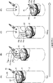
以下、本実施形態に係るキャビティ51を有するピストン5が用いられた場合の筒内流動について、図13~図18を参照して説明する。図13~図15では、図5の第3運転領域(SI燃焼)において肝要となるタンブル流が維持される状況が示されている。図16~図18では、第1、第2運転領域(SPCCI燃焼)において肝要となるスワール流が維持される状況が示されている。図13、図14、図16、図17では、気筒2が簡略的に示されていると共に、ピストン5、インジェクタ15及び点火プラグ16の位置関係が示されている。
図13(A)~(D)は、SI燃焼の吸気行程におけるタンブル流の流動を模式的に示す図である。ここでは、タンブル比=2(排気TDC~圧縮TDCの間にタンブル流が2回転する)である例を示す。図13(A)は、ピストン5が排気TDCの位置にある状態を示している。この状態では、吸気弁11は開いておらず、吸気ポート9から新気は気筒2(燃焼室6)に流入していない。
図16(A)~(D)は、吸気行程におけるスワール流の流動を模式的に示す図である。図16(A)は、ピストン5が排気TDCの位置にある状態を示している。この状態では、吸気弁11は開いておらず、吸気ポート9から新気は気筒2(燃焼室6)に流入していない。既述の通り、SPCCI燃焼においてスワール流の形成が必要とされる際、スワール弁17の開度が制限され、新気は専ら吸気ポート9Aから導入される(図3)。
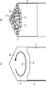
図19は、本実施形態を採用した場合における、タンブル流及びスワール流の維持効果を示すグラフである。当該グラフの横軸は、H1/H2の値を、縦軸はタンブル流及びスワール流の存続度合いを示す評価値であるスワール比及びタンブル比の値を各々示している。ここでは、H1/H2の値を、
3.00;H1=7.00mm、H2=2.34mm、
2.12;H1=11.50mm、H2=5.13mm、及び
1.93;H1=8.49mm、H2=4.39mm、
に設定したときの、スワール比及びタンブル比の値がプロットされている。なお、ボア径B=83.5mm、ストロークS=91.2mmである。さらに図19には、各々のプロットに基づいた近似曲線である、スワール比特性Cs及びタンブル比特性Ctが示されている。スワール比特性Cs及びタンブル比特性Ctは、H1/H2とスワール比及びタンブル比との関係を示す曲線である。
以上、本発明の実施形態につき説明したが、本発明はこれに限定されるものではなく、種々の変形実施形態を取ることができる。例えば、上記実施形態では、上記(1)式及び(2)式のほか、H1/D、D/B、B/F、R/B、R/Rf及びR/Rr、R/Rin及びR/Rexについても数値範囲を示した。これらについては、H1/H2の数値範囲が上記(1)式及び(2)式の範囲を満たしている限りにおいて、上記で例示した数値範囲から外れるものであってもよい。
2 気筒
5 ピストン
5C 側周面(外縁部)
50 冠面
51 キャビティ
51B 最深部
511 底部
52F F側凸部(一対の第1隆起部)
52R R側凸部(一対の第1隆起部)
522 稜線部
55 IN側斜面部(第2隆起部)
6 燃焼室
6U 燃焼室天井面(ペントルーフ型の天井面)
AX 気筒軸
Fs スワール流
Ft タンブル流
H1 FR周壁高さ(第1隆起部の高さ)
H2 IN側周壁高さ(第2隆起部の高さ)
Claims (4)
- 吸気ポート及び排気ポートの開口を有し、ピストンの冠面と、前記ピストンが摺動可能に収容される気筒の内壁面と、ペントルーフ型の天井面とによって区画される燃焼室を有し、混合気の一部を火花点火によりSI燃焼させると共にその他の混合気を自着火によりCI燃焼させる部分圧縮着火燃焼を行うエンジンの燃焼室構造であって、
前記冠面には、
椀状に凹設されてなるキャビティと、
前記キャビティと前記ピストンの外縁部との間の外周領域において気筒軸方向に突設され、前記天井面のペントルーフ形状に沿った山型形状を有する一対の第1隆起部と、
前記外周領域の、前記吸気ポートと対向する側であって前記一対の第1隆起部の間の位置に突設され、前記第1隆起部の稜線延在方向と立ち上がり方向が直交する第2隆起部と、を備え、
前記キャビティの最深部の高さ位置に対する前記第1隆起部の高さをH1、前記第2隆起部の高さをH2とするとき、前記第1隆起部の高さH1と前記第2隆起部の高さH2との比であるH1/H2が、1.79以上3.29以下の範囲に設定されていることを特徴とするエンジンの燃焼室構造。 - 吸気ポート及び排気ポートの開口を有し、ピストンの冠面と、前記ピストンが摺動可能に収容される気筒の内壁面と、ペントルーフ型の天井面とによって区画される燃焼室を有し、混合気を火花点火により燃焼させるSI燃焼と、混合気の一部を火花点火によりSI燃焼させると共にその他の混合気を自着火によりCI燃焼させる部分圧縮着火燃焼とを併用して行うエンジンの燃焼室構造であって、
前記冠面には、
椀状に凹設されてなるキャビティと、
前記キャビティと前記ピストンの外縁部との間の外周領域において気筒軸方向に突設され、前記天井面のペントルーフ形状に沿った山型形状を有する一対の第1隆起部と、
前記外周領域の、前記吸気ポートと対向する側であって前記一対の第1隆起部の間の位置に突設され、前記第1隆起部の稜線延在方向と立ち上がり方向が直交する第2隆起部と、を備え、
前記キャビティの最深部の高さ位置に対する前記第1隆起部の高さをH1、前記第2隆起部の高さをH2とするとき、前記第1隆起部の高さH1と前記第2隆起部の高さH2との比であるH1/H2が、1.92以上2.75以下の範囲に設定されていることを特徴とするエンジンの燃焼室構造。 - 請求項1又は2に記載のエンジンの燃焼室構造において、
前記気筒の幾何学的圧縮比が15以上の高圧縮比に設定されている、エンジンの燃焼室構造。 - 請求項1~3のいずれか1項に記載のエンジンの燃焼室構造において、
前記キャビティは、前記冠面の上面視において、前記稜線延在方向に幅広の楕円形状を備える、エンジンの燃焼室構造。
Priority Applications (2)
| Application Number | Priority Date | Filing Date | Title |
|---|---|---|---|
| JP2018215642A JP7180304B2 (ja) | 2018-11-16 | 2018-11-16 | エンジンの燃焼室構造 |
| US16/678,305 US11015515B2 (en) | 2018-11-16 | 2019-11-08 | Combustion chamber structure for engine |
Applications Claiming Priority (1)
| Application Number | Priority Date | Filing Date | Title |
|---|---|---|---|
| JP2018215642A JP7180304B2 (ja) | 2018-11-16 | 2018-11-16 | エンジンの燃焼室構造 |
Publications (2)
| Publication Number | Publication Date |
|---|---|
| JP2020084797A JP2020084797A (ja) | 2020-06-04 |
| JP7180304B2 true JP7180304B2 (ja) | 2022-11-30 |
Family
ID=70727032
Family Applications (1)
| Application Number | Title | Priority Date | Filing Date |
|---|---|---|---|
| JP2018215642A Active JP7180304B2 (ja) | 2018-11-16 | 2018-11-16 | エンジンの燃焼室構造 |
Country Status (2)
| Country | Link |
|---|---|
| US (1) | US11015515B2 (ja) |
| JP (1) | JP7180304B2 (ja) |
Families Citing this family (3)
| Publication number | Priority date | Publication date | Assignee | Title |
|---|---|---|---|---|
| JP7537234B2 (ja) * | 2020-11-10 | 2024-08-21 | マツダ株式会社 | エンジンの制御方法及びエンジンシステム |
| JP7616524B2 (ja) * | 2021-10-14 | 2025-01-17 | 三菱自動車工業株式会社 | 内燃機関用ピストン |
| CN114837799B (zh) * | 2022-06-07 | 2023-07-28 | 一汽解放汽车有限公司 | 一种柴油机燃烧室和柴油机 |
Citations (3)
| Publication number | Priority date | Publication date | Assignee | Title |
|---|---|---|---|---|
| JP2016121564A (ja) | 2014-12-24 | 2016-07-07 | 三菱自動車工業株式会社 | 筒内噴射式エンジン用ピストン |
| JP2016121630A (ja) | 2014-12-25 | 2016-07-07 | マツダ株式会社 | 直噴エンジンの燃焼室構造 |
| JP2018087565A (ja) | 2016-11-22 | 2018-06-07 | マツダ株式会社 | 圧縮自己着火式エンジンの制御装置 |
Family Cites Families (34)
| Publication number | Priority date | Publication date | Assignee | Title |
|---|---|---|---|---|
| DE19713030C2 (de) * | 1996-04-01 | 2000-02-24 | Avl List Gmbh | Viertakt-Brennkraftmaschine mit Fremdzündung |
| DE19713029C2 (de) * | 1996-04-01 | 2000-02-24 | Avl List Gmbh | Viertakt-Brennkraftmaschine mit Fremdzündung |
| JP3030415B2 (ja) * | 1997-04-17 | 2000-04-10 | 三菱自動車工業株式会社 | 筒内噴射エンジンのピストン |
| JP3284922B2 (ja) * | 1997-05-20 | 2002-05-27 | 日産自動車株式会社 | 筒内噴射式内燃機関のピストン |
| JPH11182336A (ja) * | 1997-12-18 | 1999-07-06 | Nissan Motor Co Ltd | 直噴火花点火式内燃機関のピストン |
| US6129070A (en) * | 1997-06-03 | 2000-10-10 | Nissan Motor Co., Ltd. | Piston for cylinder direct injection spark ignition internal combustion engine |
| AT2378U1 (de) * | 1997-08-28 | 1998-09-25 | Avl List Gmbh | Brennkraftmaschine mit fremdzündung |
| JPH11148355A (ja) * | 1997-11-14 | 1999-06-02 | Mazda Motor Corp | 筒内噴射型火花点火式エンジン |
| JP3362657B2 (ja) * | 1998-01-30 | 2003-01-07 | トヨタ自動車株式会社 | スパークアシスト式自着火内燃機関 |
| DE19836707A1 (de) * | 1998-03-04 | 2000-02-17 | Audi Ag | Direkteinspritzende Brennkraftmaschine |
| JP3353709B2 (ja) * | 1998-07-08 | 2002-12-03 | トヨタ自動車株式会社 | 筒内噴射式火花点火内燃機関 |
| DE19835563A1 (de) * | 1998-08-06 | 2000-02-10 | Volkswagen Ag | Viertakt-Brennkraftmaschine mit Direkteinspritzung |
| JP3840823B2 (ja) * | 1998-12-10 | 2006-11-01 | マツダ株式会社 | 筒内噴射式エンジン |
| JP3596320B2 (ja) * | 1998-12-21 | 2004-12-02 | 日産自動車株式会社 | 筒内噴射式火花点火機関のピストン |
| JP3389873B2 (ja) * | 1999-02-05 | 2003-03-24 | トヨタ自動車株式会社 | 筒内噴射式火花点火内燃機関 |
| JP3362690B2 (ja) * | 1999-03-02 | 2003-01-07 | トヨタ自動車株式会社 | 筒内噴射式火花点火内燃機関 |
| JP2000248945A (ja) * | 1999-03-02 | 2000-09-12 | Suzuki Motor Corp | 筒内直接噴射エンジン |
| JP4465849B2 (ja) * | 2000-09-29 | 2010-05-26 | マツダ株式会社 | 火花点火式直噴エンジン |
| US6745745B2 (en) * | 2002-02-22 | 2004-06-08 | General Motors Corporation | Combustion chamber for reverse tumble spark ignition direct injection engine |
| KR100588542B1 (ko) * | 2003-12-30 | 2006-06-14 | 현대자동차주식회사 | 직접 분사식 엔진 |
| JP4442542B2 (ja) * | 2005-09-30 | 2010-03-31 | マツダ株式会社 | 往復動ピストン型エンジン |
| JP4582217B2 (ja) * | 2008-07-17 | 2010-11-17 | マツダ株式会社 | 火花点火式直噴エンジン |
| JP2010150969A (ja) * | 2008-12-24 | 2010-07-08 | Mazda Motor Corp | 火花点火式直噴エンジン |
| WO2012001887A1 (en) * | 2010-06-29 | 2012-01-05 | Kolbenschmidt K.K. | Piston for spark-ignition engine |
| US9810167B2 (en) * | 2013-01-16 | 2017-11-07 | Mazda Motor Corporation | Catalyst advanced warmup control device for spark ignition engine |
| JP6056836B2 (ja) * | 2014-11-18 | 2017-01-11 | マツダ株式会社 | 直噴エンジンの燃焼室構造 |
| JP6260795B2 (ja) * | 2015-03-27 | 2018-01-17 | マツダ株式会社 | エンジンの燃料制御装置 |
| JP6323683B2 (ja) | 2015-06-03 | 2018-05-16 | マツダ株式会社 | エンジンの制御装置 |
| JP6323684B2 (ja) * | 2015-06-03 | 2018-05-16 | マツダ株式会社 | エンジンの制御装置 |
| JP6323686B2 (ja) * | 2015-07-07 | 2018-05-16 | マツダ株式会社 | エンジンの制御装置 |
| JP6088015B1 (ja) * | 2015-09-18 | 2017-03-01 | 富士重工業株式会社 | 燃料噴射装置 |
| JP6565999B2 (ja) * | 2017-06-02 | 2019-08-28 | マツダ株式会社 | エンジン |
| JP6566000B2 (ja) * | 2017-06-02 | 2019-08-28 | マツダ株式会社 | エンジン |
| JP7155918B2 (ja) * | 2018-11-16 | 2022-10-19 | マツダ株式会社 | エンジンの燃焼室構造 |
-
2018
- 2018-11-16 JP JP2018215642A patent/JP7180304B2/ja active Active
-
2019
- 2019-11-08 US US16/678,305 patent/US11015515B2/en active Active
Patent Citations (3)
| Publication number | Priority date | Publication date | Assignee | Title |
|---|---|---|---|---|
| JP2016121564A (ja) | 2014-12-24 | 2016-07-07 | 三菱自動車工業株式会社 | 筒内噴射式エンジン用ピストン |
| JP2016121630A (ja) | 2014-12-25 | 2016-07-07 | マツダ株式会社 | 直噴エンジンの燃焼室構造 |
| JP2018087565A (ja) | 2016-11-22 | 2018-06-07 | マツダ株式会社 | 圧縮自己着火式エンジンの制御装置 |
Also Published As
| Publication number | Publication date |
|---|---|
| US11015515B2 (en) | 2021-05-25 |
| JP2020084797A (ja) | 2020-06-04 |
| US20200158007A1 (en) | 2020-05-21 |
Similar Documents
| Publication | Publication Date | Title |
|---|---|---|
| CN109931175B (zh) | 压燃式发动机的控制装置 | |
| CN109931170B (zh) | 压燃式发动机的控制装置 | |
| CN109931176B (zh) | 压燃式发动机的控制装置 | |
| EP3499007B1 (en) | Control system for engine, engine, method of controlling engine, and computer program product | |
| US10641192B2 (en) | Control system for compression-ignition engine | |
| EP1108868A2 (en) | Compression self-ignition gasoline engine | |
| JP7137118B2 (ja) | ディーゼルエンジンの燃料噴射制御装置 | |
| CN108884777A (zh) | 发动机的控制装置 | |
| JP2020002862A (ja) | ディーゼルエンジンの燃料噴射制御装置 | |
| JP7180304B2 (ja) | エンジンの燃焼室構造 | |
| JP7155918B2 (ja) | エンジンの燃焼室構造 | |
| JP2020084910A (ja) | エンジンの制御装置 | |
| JP2004245171A (ja) | 混合気を圧縮自着火させる自着火運転が可能な内燃機関 | |
| JP7196553B2 (ja) | エンジンの燃焼室構造 | |
| JP7155916B2 (ja) | エンジンの燃焼室構造 | |
| JP7283055B2 (ja) | エンジンの燃焼室構造 | |
| JP7155917B2 (ja) | エンジンの燃焼室構造 | |
| JP7271912B2 (ja) | エンジンの燃焼室構造 | |
| JP2005163686A (ja) | 混合気を圧縮自着火させる自着火運転が可能な内燃機関 | |
| JP7163634B2 (ja) | ディーゼルエンジンの燃料噴射制御装置 | |
| JP7771784B2 (ja) | 圧縮着火エンジンの制御装置 | |
| JP2020084911A (ja) | エンジンの制御装置及び制御方法 | |
| JP7163635B2 (ja) | ディーゼルエンジンの燃料噴射制御装置 |
Legal Events
| Date | Code | Title | Description |
|---|---|---|---|
| A621 | Written request for application examination |
Free format text: JAPANESE INTERMEDIATE CODE: A621 Effective date: 20210720 |
|
| A977 | Report on retrieval |
Free format text: JAPANESE INTERMEDIATE CODE: A971007 Effective date: 20220622 |
|
| A131 | Notification of reasons for refusal |
Free format text: JAPANESE INTERMEDIATE CODE: A131 Effective date: 20220705 |
|
| A521 | Request for written amendment filed |
Free format text: JAPANESE INTERMEDIATE CODE: A523 Effective date: 20220830 |
|
| TRDD | Decision of grant or rejection written | ||
| A01 | Written decision to grant a patent or to grant a registration (utility model) |
Free format text: JAPANESE INTERMEDIATE CODE: A01 Effective date: 20221018 |
|
| A61 | First payment of annual fees (during grant procedure) |
Free format text: JAPANESE INTERMEDIATE CODE: A61 Effective date: 20221031 |
|
| R150 | Certificate of patent or registration of utility model |
Ref document number: 7180304 Country of ref document: JP Free format text: JAPANESE INTERMEDIATE CODE: R150 |