EP1319822B9 - Moteur à combustion avec injection directe - Google Patents
Moteur à combustion avec injection directe Download PDFInfo
- Publication number
- EP1319822B9 EP1319822B9 EP01129782A EP01129782A EP1319822B9 EP 1319822 B9 EP1319822 B9 EP 1319822B9 EP 01129782 A EP01129782 A EP 01129782A EP 01129782 A EP01129782 A EP 01129782A EP 1319822 B9 EP1319822 B9 EP 1319822B9
- Authority
- EP
- European Patent Office
- Prior art keywords
- fuel
- combustion chamber
- combustion engine
- cylinder
- internal combustion
- Prior art date
- Legal status (The legal status is an assumption and is not a legal conclusion. Google has not performed a legal analysis and makes no representation as to the accuracy of the status listed.)
- Expired - Lifetime
Links
Images
Classifications
-
- F—MECHANICAL ENGINEERING; LIGHTING; HEATING; WEAPONS; BLASTING
- F02—COMBUSTION ENGINES; HOT-GAS OR COMBUSTION-PRODUCT ENGINE PLANTS
- F02F—CYLINDERS, PISTONS OR CASINGS, FOR COMBUSTION ENGINES; ARRANGEMENTS OF SEALINGS IN COMBUSTION ENGINES
- F02F1/00—Cylinders; Cylinder heads
- F02F1/24—Cylinder heads
- F02F1/242—Arrangement of spark plugs or injectors
-
- F—MECHANICAL ENGINEERING; LIGHTING; HEATING; WEAPONS; BLASTING
- F02—COMBUSTION ENGINES; HOT-GAS OR COMBUSTION-PRODUCT ENGINE PLANTS
- F02B—INTERNAL-COMBUSTION PISTON ENGINES; COMBUSTION ENGINES IN GENERAL
- F02B23/00—Other engines characterised by special shape or construction of combustion chambers to improve operation
- F02B23/08—Other engines characterised by special shape or construction of combustion chambers to improve operation with positive ignition
- F02B23/10—Other engines characterised by special shape or construction of combustion chambers to improve operation with positive ignition with separate admission of air and fuel into cylinder
- F02B23/101—Other engines characterised by special shape or construction of combustion chambers to improve operation with positive ignition with separate admission of air and fuel into cylinder the injector being placed on or close to the cylinder centre axis, e.g. with mixture formation using spray guided concepts
-
- F—MECHANICAL ENGINEERING; LIGHTING; HEATING; WEAPONS; BLASTING
- F02—COMBUSTION ENGINES; HOT-GAS OR COMBUSTION-PRODUCT ENGINE PLANTS
- F02F—CYLINDERS, PISTONS OR CASINGS, FOR COMBUSTION ENGINES; ARRANGEMENTS OF SEALINGS IN COMBUSTION ENGINES
- F02F1/00—Cylinders; Cylinder heads
- F02F1/24—Cylinder heads
- F02F1/26—Cylinder heads having cooling means
- F02F1/36—Cylinder heads having cooling means for liquid cooling
- F02F1/38—Cylinder heads having cooling means for liquid cooling the cylinder heads being of overhead valve type
-
- F—MECHANICAL ENGINEERING; LIGHTING; HEATING; WEAPONS; BLASTING
- F02—COMBUSTION ENGINES; HOT-GAS OR COMBUSTION-PRODUCT ENGINE PLANTS
- F02B—INTERNAL-COMBUSTION PISTON ENGINES; COMBUSTION ENGINES IN GENERAL
- F02B75/00—Other engines
- F02B75/12—Other methods of operation
- F02B2075/125—Direct injection in the combustion chamber for spark ignition engines, i.e. not in pre-combustion chamber
-
- F—MECHANICAL ENGINEERING; LIGHTING; HEATING; WEAPONS; BLASTING
- F02—COMBUSTION ENGINES; HOT-GAS OR COMBUSTION-PRODUCT ENGINE PLANTS
- F02F—CYLINDERS, PISTONS OR CASINGS, FOR COMBUSTION ENGINES; ARRANGEMENTS OF SEALINGS IN COMBUSTION ENGINES
- F02F1/00—Cylinders; Cylinder heads
- F02F1/24—Cylinder heads
- F02F2001/241—Cylinder heads specially adapted to pent roof shape of the combustion chamber
-
- F—MECHANICAL ENGINEERING; LIGHTING; HEATING; WEAPONS; BLASTING
- F02—COMBUSTION ENGINES; HOT-GAS OR COMBUSTION-PRODUCT ENGINE PLANTS
- F02F—CYLINDERS, PISTONS OR CASINGS, FOR COMBUSTION ENGINES; ARRANGEMENTS OF SEALINGS IN COMBUSTION ENGINES
- F02F1/00—Cylinders; Cylinder heads
- F02F1/24—Cylinder heads
- F02F2001/244—Arrangement of valve stems in cylinder heads
- F02F2001/245—Arrangement of valve stems in cylinder heads the valve stems being orientated at an angle with the cylinder axis
-
- Y—GENERAL TAGGING OF NEW TECHNOLOGICAL DEVELOPMENTS; GENERAL TAGGING OF CROSS-SECTIONAL TECHNOLOGIES SPANNING OVER SEVERAL SECTIONS OF THE IPC; TECHNICAL SUBJECTS COVERED BY FORMER USPC CROSS-REFERENCE ART COLLECTIONS [XRACs] AND DIGESTS
- Y02—TECHNOLOGIES OR APPLICATIONS FOR MITIGATION OR ADAPTATION AGAINST CLIMATE CHANGE
- Y02T—CLIMATE CHANGE MITIGATION TECHNOLOGIES RELATED TO TRANSPORTATION
- Y02T10/00—Road transport of goods or passengers
- Y02T10/10—Internal combustion engine [ICE] based vehicles
- Y02T10/12—Improving ICE efficiencies
Definitions
- the invention relates to a method for producing an air-fuel mixture in a limited by a cylinder and a piston combustion chamber of a direct injection internal combustion engine, according to claim 7, the first part.
- a gasoline-powered four-stroke engine with direct injection is known in which a stratified lean operation is possible. With a Such operation can reduce the pumping losses of the engine and therefore, as compared with conventional intake manifold injection engine technology and homogeneous stoichiometric operation, substantial improvements in fuel economy can be achieved.
- various design principles are known which differ with regard to the system components. The differences include, for example, the arrangement of the injectors and the igniters, the number of intake and exhaust valves, the geometric shape of the combustion chamber and the piston, and the air movement in the combustion chamber produced by the shape of the intake passage.
- combustion systems are classified as wall-mounted, air-guided, or spray-guided systems.
- the systems currently in production typically comprise wall-mounted systems with a centrally located spark plug and a side mounted injector.
- the fuel spray is directed through the walls or a cavity in the piston to the location of ignition, which presents a number of tradeoffs with timing Injection and ignition and resulting losses in the thermal efficiency of the engine caused.
- the JP 01110827 A shows a diesel internal combustion engine with direct injection, in which an injection nozzle is provided with a plurality of radially aligned, mounted on the outer circumference of the injection nozzle nozzle bores.
- the nozzle bores have with respect to a central longitudinal axis of the injection nozzle, which corresponds to a rotation axis of a swirling movement of the intake air flowing into the combustion chamber in the direction of rotation of the swirling motion increasingly larger nozzle bores and are aligned in the direction of rotation of the swirling movement increasingly larger angles to each other.
- a first nozzle bore is arranged opposite a spark plug electrode provided in the combustion chamber such that a fuel jet issuing from this nozzle bore exits the injection nozzle directly in the direction of the spark plug electrode.
- the EP 0 694 682 A1 shows a direct injection internal combustion engine in which a Einspitzdüse is arranged laterally on a combustion chamber, while a spark plug electrode is arranged centrally on an upper side of the combustion chamber.
- the combustion chamber is partially bounded by a depression in a surface of a piston.
- This depression in the piston has a sequence of curved and straight wall sections viewed in a direction of rotation, in order to ensure a targeted supply of fuel particles or fuel mist to the spark plug during a swirling movement of the intake air.
- the internal combustion engine according to the invention with direct injection contains at least one cylinder with lateral cylinder walls and a cylinder head and a piston arranged in the cylinder, wherein the piston and the cylinder together define a combustion chamber.
- the combustion chamber has at least one air inlet, which is designed and arranged on the cylinder, that upon influx of inlet air, a swirling movement of the intake air is formed in the combustion chamber, which is preferably inclined.
- a swirl movement is characterized by a vortex rotating around the cylinder axis or lifting axis of the piston.
- the internal combustion engine at the top of the combustion chamber i. in the cylinder head, centrally a fuel injector for injecting a fuel jet whose liquid particles limit an injection volume, and arranged an ignition device, wherein the electrodes of the ignition device are outside of said injection volume of the fuel injector.
- the electrodes are therefore not directly hit by the injected fuel.
- the injection volume is defined as the space area reached by the liquid particles of the injected fuel.
- the internal combustion engine is characterized in that said injection volume is asymmetrical with respect to an axis of the fuel injector, the injection volume being further shaped and aligned within the combustion chamber such that the electrodes of the ignition device are in a fuel mist created by evaporating fuel during and after injection occupied volume lie.
- the internal combustion engine designed in the above-described manner has the advantage of a long service life, since soot deposits on the ignition device and coking of the fuel injector are prevented or minimized become. This happens on the one hand in that the ignition device is not directly hit by fuel droplets, because it lies with their electrodes outside the injection volume. At the same time, however, a safe and robust ignition of the air-fuel mixture is ensured, since the electrodes are arranged in a region which is occupied by the fuel mist.
- the electrodes of the ignition device are arranged in a region which, when the asymmetrical injection volume is rotated, is swept over the cylinder axis or stroke axis of the piston. Such rotation of the injection volume is ensured by the swirling movement of the intake air generated by the configuration of the air intake.
- the top of the combustion chamber i. the cylinder head, according to an embodiment of the invention may have the shape of a roof. This shape of the cylinder head conveniently allows the accommodation of the injector and the ignition device.
- the top of the piston may have a trough-shaped depression, which serves advantageously to deflect the injected fuel and to distribute in the combustion chamber.
- the at least one cylinder of the internal combustion engine has at least one intake valve and at least one exhaust valve, wherein said valves are controlled by a controller such that operation of the internal combustion engine with an internal exhaust gas recirculation is possible.
- the control may in particular be a variable camshaft control, which allows a shift of the opening and / or closing times of the valves in the direction of a deceleration and / or a forward displacement.
- In the internal exhaust gas recirculation is ensured by a late closing of the exhaust valves that a portion of the burned exhaust gases can flow back into the combustion chamber to produce there more favorable conditions for the subsequent power stroke.
- the fuel injector may be surrounded at the top of the combustion chamber within the cylinder head by a coolant jacket.
- a coolant jacket Such a complete enclosure of the fuel injector with a coolant jacket is also possible in particular due to the asymmetrical shape of the injection volume, which in turn permits an inclined installation of the fuel injector. This then creates the required space and distance from the ignition device for the coolant jacket.
- the good cooling of the fuel injector in turn advantageously prevents coking of the fuel injector and thus its premature wear.
- the invention further relates to a method for producing an air-fuel mixture in a combustion chamber limited by a cylinder and a piston of a direct injection internal combustion engine, wherein a preferably inclined swirl movement is generated by an air inlet associated with the combustion chamber in the combustion chamber, and wherein by means of a centrally arranged on de top of the combustion chamber fuel injector, a fuel jet whose liquid particles an injection volume limit, is injected into the combustion chamber.
- the method is characterized in that the injection volume is asymmetrical with respect to an axis of the fuel injector and the electrodes of an igniter are outside the injection volume in one of an envelope of the volume occupied by the vaporized fuel as fuel spray.
- the electrodes are preferably located in a region which the injection volume sweeps over the cylinder axis during a rotation.
- the method achieves the already explained in connection with the internal combustion engine advantage that on the one hand the electrodes are not hit directly by the fuel jet, and that on the other hand a proper ignition of the injected fuel is ensured, since the injection volume by the evaporation and / or the swirl movement of the Inlet air passes around the cylinder axis in the region of the ignition.
- a stratified air-fuel mixture can be generated in particular in the combustion chamber.
- Such a stratified mixture allows high, ignitable fuel concentrations in the region of the ignition device, while the remaining volume of the combustion chamber is filled with a mixture of lower fuel concentration. This allows in particular an efficient lean operation of the internal combustion engine.
- a first quantity of fuel is injected into the combustion chamber to produce a homogeneous air-fuel mixture, and during the subsequent compression stroke a second quantity of fuel is injected to produce a stratified mixture.
- the division of the total amount of injected fuel into two parts provides an additional parameter for controlling engine operation. This can be exploited in an advantageous manner to optimize the operation of the internal combustion engine.
- the method is preferably carried out such that in all modes of operation of the internal combustion engine, the same flow conditions are generated in the combustion chamber.
- These flow conditions can be determined by structurally relatively simple and immutable measures, so that overall a cost-effective and robust construction of the internal combustion engine can be achieved.
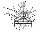
- the single FIGURE shows a cross section through the inlet region of a cylinder of an internal combustion engine according to the invention.
- a cylinder 5 is shown by preferably several cylinders of a gasoline engine with direct injection.
- the walls of the cylinder 5 and the cylinder head, which has the shape of a roof, as well as in the cylinder 5 on and from movable piston 20 together limit the combustion chamber 1.
- two intake valves 7 and two exhaust valves 8 are arranged in the cylinder head, of which in the figure only one is recognizable.
- the inlet valve 7 is seated at the end of the intake passage 17, while the exhaust valve 8 closes the inlet of the exhaust passage 18.
- the geometry of the inlet 4 is preferably fixed, that is, there are no variable swirling devices or the like.
- the inlet 4 is rather constructed so that a pronounced air movement in the cylinder 5 is generated, which consists of a strong tumble flow and a weak swirl. There is movement during the intake stroke.
- the tumble flow is characterized by swirls with an axis of rotation perpendicular to the cylinder axis 6 and is designed so that it breaks up into smaller turbulence during compression.
- the swirling movement i. a swirl about the cylinder axis 6, on the other hand, is to be maintained during compression to assist the intended generation of a stratified charge in the combustion chamber 1.
- a fuel injector 2 and a spark plug 3 are arranged. This arrangement allows a maximum diameter for the intake valves 7 and the exhaust valves 8.
- the fuel injector 2 is designed such that it generates a special arrangement and shape of the injection volume 9, which ensures the best possible interaction with the ignition device 3.
- the injection volume 9 is defined as the space area which is directly reached by the liquid particles of the injected fuel. According to the invention, this injection volume 9 is formed asymmetrically with respect to the distribution of the fuel jet within a cross section through the injection jet perpendicular to the axis of the injection jet or the injector 10. The asymmetry is specifically designed so that the location of the ignition, ie the location of the electrodes of the spark plug 3, is located within the entire envelope of the resulting fuel spray so that it is safely reached by the vaporized fuel, but never directly struck by the liquid fuel ,
- the top of the piston 20 is characterized by a particularly designed course 11 with a central trough 12, which for receiving the stratified charge, which is generated by the injector 2, and for deflecting the propagating beam tips back into the central mixing volume in the case of serves very far-reaching Strahlvordringens.
- the trough 12 in the piston 20 also allows a maximum free penetration of the fuel jet without hitting a wall.
- Squish surfaces are disposed on the side of the inlet 14 and the outlet 15 and in the region of the roof to ensure better homogeneous combustion characteristics.
- the tumble component of the air movement in the cylinder produced by the inlet 4 is thereby better converted into turbulence in order to achieve an improved homogenization of the mixture and an increased combustion rate.
- the intake passage 17 and the exhaust passage 18 are constructed and shaped to allow the provision of an optimized cooling water jacket 19 around the centrally located fuel injector 2. Further, there is open access of air movement to the tip of the fuel injector 2 to allow proper cleaning of the tip area and prevent the formation of deposits.
- the figure thus shows a total of an internal combustion engine with direct injection and a central arrangement of the fuel injector 2 and the ignition device. 3 in a combustion chamber 1 with a roof, the injector 2 injecting the fuel in the form of a distributed spray and the inlet valves 7 providing an inlet flow into the cylinder 5 which produces an inclined swirling motion in the cylinder and the inlet and exhaust valves of the engine are actuated by a variable camshaft control, by which an internal exhaust gas recirculation is made possible. It is important to the internal combustion engine that there be a fuel jet for stratified fuel injection having an asymmetric shape in which the igniter 3 is within the general envelope of the fuel spray produced, but prevents the igniter from being directly exposed to liquid fuel from the fuel spray ,
- the internal combustion engine is preferably operated without any external exhaust gas recirculation.
Landscapes
- Engineering & Computer Science (AREA)
- Chemical & Material Sciences (AREA)
- Combustion & Propulsion (AREA)
- Mechanical Engineering (AREA)
- General Engineering & Computer Science (AREA)
- Combustion Methods Of Internal-Combustion Engines (AREA)
Claims (9)
- Moteur à combustion interne à injection directe comprenant :a) au moins un cylindre (5) et un piston (20) disposé dans celui-ci, le cylindre et le piston délimitant ensemble une chambre de combustion (1) ;b) au moins une entrée d'air (17) qui est configurée et disposée sur le cylindre de manière à produire un mouvement de tourbillonnement de préférence incliné de l'air d'admission dans la chambre de combustion ;c) un injecteur de carburant (2) centré sur le côté supérieur de la chambre de combustion pour injecter un jet de carburant dont les gouttelettes de liquide définissent un volume d'injection (9) ;d) un dispositif d'allumage (3) centré sur le côté supérieur de la chambre de combustion dont les électrodes se trouvent à l'extérieur du volume d'injection de l'injecteur de carburant ;caractérisé en ce que le volume d'injection présente une forme asymétrique par rapport à un axe de l'injecteur de carburant (2), les électrodes du dispositif d'allumage (3) se trouvant dans une enveloppe du volume occupé par le carburant vaporisé sous la forme d'un nuage de carburant.
- Moteur à combustion interne selon la revendication 1, caractérisé en ce que les électrodes du dispositif d'allumage (3) se trouvent dans la zone balayée lors d'une rotation du volume d'injection (9) autour de l'axe du cylindre (6).
- Moteur à combustion interne selon la revendication 1 ou 2, caractérisé en ce que le côté supérieur de la chambre de combustion (1) présente la forme d'un toit.
- Moteur à combustion interne selon l'une des revendications 1 à 3, caractérisé en ce que le côté supérieur (11) du piston (20) présente une excavation (12).
- Moteur à combustion interne selon l'une des revendications 1 à 4, caractérisé en ce que le cylindre (5) présente au moins une soupape d'admission (7) et au moins une soupape d'échappement (8) qui sont commandées de telle sorte qu'un fonctionnement avec un retour interne des gaz d'échappement soit possible.
- Moteur à combustion interne selon l'une des revendications 1 à 5, caractérisé en ce que l'injecteur de carburant (2) dans la culasse au-dessus de la chambre de combustion (1) est entouré d'une enveloppe de liquide de refroidissement (19).
- Procédé pour générer un mélange air/carburant dans une chambre de combustion (1) d'un moteur à combustion interne à injection directe délimitée par un cylindre (5) et un piston (20), un mouvement de tourbillonnement de préférence incliné étant généré dans la chambre de combustion par le biais d'une entrée d'air (17) affectée à la chambre de combustion (1) et un jet de carburant dont les gouttelettes de liquide définissent un volume d'injection (9) étant injecté dans la chambre de combustion au moyen d'un injecteur de carburant (2) centré sur le côté supérieur de la chambre de combustion (1), un dispositif d'allumage, dont les électrodes se trouvent à l'extérieur du volume d'injection de l'injecteur de carburant étant prévu centré sur le côté supérieur de la chambre de combustion, caractérisé en ce que le volume d'injection présente une forme asymétrique par rapport à un axe de l'injecteur de carburant (2) et les électrodes du dispositif d'injection (3) se trouvent à l'extérieur du volume d'injection dans un volume occupé par une enveloppe du carburant vaporisé sous la forme d'un nuage de carburant.
- Procédé selon la revendication 7, caractérisé en ce qu'une première quantité de carburant est injectée pendant le cycle d'aspiration pour produire un mélange air/carburant homogène et une deuxième quantité de carburant est injectée pendant le cycle de compression pour produire un mélange air/carburant stratifié.
- Procédé selon la revendication 7 ou 8, caractérisé en ce que les mêmes conditions d'écoulement sont produites dans la chambre de combustion dans tous les modes de fonctionnement du moteur à combustion interne.
Priority Applications (3)
| Application Number | Priority Date | Filing Date | Title |
|---|---|---|---|
| DE50112871T DE50112871D1 (de) | 2001-12-14 | 2001-12-14 | Brennkraftmaschine mit Direkteinspritzung |
| EP01129782A EP1319822B9 (fr) | 2001-12-14 | 2001-12-14 | Moteur à combustion avec injection directe |
| US10/318,844 US6799550B2 (en) | 2001-12-14 | 2002-12-13 | Spark-ignition engine having direct fuel injection |
Applications Claiming Priority (1)
| Application Number | Priority Date | Filing Date | Title |
|---|---|---|---|
| EP01129782A EP1319822B9 (fr) | 2001-12-14 | 2001-12-14 | Moteur à combustion avec injection directe |
Publications (3)
| Publication Number | Publication Date |
|---|---|
| EP1319822A1 EP1319822A1 (fr) | 2003-06-18 |
| EP1319822B1 EP1319822B1 (fr) | 2007-08-15 |
| EP1319822B9 true EP1319822B9 (fr) | 2007-12-26 |
Family
ID=8179540
Family Applications (1)
| Application Number | Title | Priority Date | Filing Date |
|---|---|---|---|
| EP01129782A Expired - Lifetime EP1319822B9 (fr) | 2001-12-14 | 2001-12-14 | Moteur à combustion avec injection directe |
Country Status (3)
| Country | Link |
|---|---|
| US (1) | US6799550B2 (fr) |
| EP (1) | EP1319822B9 (fr) |
| DE (1) | DE50112871D1 (fr) |
Families Citing this family (19)
| Publication number | Priority date | Publication date | Assignee | Title |
|---|---|---|---|---|
| US6832594B2 (en) * | 2002-01-09 | 2004-12-21 | Nissan Motor Co., Ltd. | Direct fuel injection engine |
| JP2006052666A (ja) * | 2004-08-11 | 2006-02-23 | Nissan Motor Co Ltd | 筒内直接噴射式内燃機関 |
| US7185614B2 (en) * | 2004-10-28 | 2007-03-06 | Caterpillar Inc | Double bowl piston |
| DE102005002389B4 (de) * | 2005-01-19 | 2009-04-23 | Fev Motorentechnik Gmbh | Fahrzeug-Kolben-Brennkraftmaschine mit angepasster Mulde |
| JP4742802B2 (ja) * | 2005-10-19 | 2011-08-10 | 日産自動車株式会社 | 筒内直噴エンジン |
| DE102006037413B4 (de) * | 2006-08-10 | 2008-05-29 | Ford Global Technologies, LLC, Dearborn | Direkteinspritzende fremdgezündete Brennkraftmaschine und Verfahren zum Betreiben einer derartigen Brennkraftmaschine |
| US7849682B2 (en) * | 2006-08-31 | 2010-12-14 | Caterpillar Inc | Exhaust treatment device having a fuel powered burner |
| ATE529618T1 (de) * | 2007-04-06 | 2011-11-15 | Honda Motor Co Ltd | Direkteinspritzmotor |
| DE102008036840B4 (de) | 2008-08-07 | 2013-08-01 | Ford Global Technologies, Llc | Direkteinspritzende fremdgezündete Brennkraftmaschine mit Einspritzdüse |
| US20110231316A1 (en) * | 2010-03-09 | 2011-09-22 | Cummins Intellectual Properties, Inc. | Method, system and computer readable media containing a program for identifying whether a product is genuine |
| WO2011112702A2 (fr) | 2010-03-09 | 2011-09-15 | Cummins Filtration Ip, Inc. | Appareil, système et procédé permettant de détecter la présence de composants de produits révisables authentiques |
| US20110277718A1 (en) * | 2010-05-17 | 2011-11-17 | Gm Global Technology Operations, Inc. | Engine including valve geometry relative to bore size |
| CN203584599U (zh) | 2011-03-17 | 2014-05-07 | 康明斯知识产权公司 | 用于内燃发动机的活塞 |
| US8833327B2 (en) | 2011-12-28 | 2014-09-16 | Cummins Intellectual Property, Inc. | Piston and combustion chamber |
| CN103835803B (zh) * | 2014-02-24 | 2016-02-24 | 大连理工大学 | 柴油机碰撞分流燃烧室 |
| US11053838B2 (en) * | 2014-11-06 | 2021-07-06 | Westport Fuel Systems Canada Inc. | Combustion chamber geometry |
| US9611806B2 (en) | 2014-11-18 | 2017-04-04 | Caterpillar Inc. | Engine piston |
| CA3004539C (fr) * | 2015-11-10 | 2023-08-22 | Nissan Motor Co., Ltd. | Procede et dispositif permettant de commander un moteur a combustion interne |
| CN106640455A (zh) * | 2016-11-25 | 2017-05-10 | 奇瑞汽车股份有限公司 | 一种直喷汽油机中置喷油器的缸盖燃烧系统 |
Family Cites Families (33)
| Publication number | Priority date | Publication date | Assignee | Title |
|---|---|---|---|---|
| DE3019330A1 (de) * | 1980-05-21 | 1981-11-26 | Volkswagenwerk Ag, 3180 Wolfsburg | Fremdgezuendete viertakt-brennkraft-maschine mit direkteinspritzung |
| DE3533014A1 (de) * | 1985-09-16 | 1987-03-26 | Avl Verbrennungskraft Messtech | Verfahren und einrichtung zur einbringung des kraftstoffes in den brennraum eines dieselmotors |
| JP2564854B2 (ja) * | 1987-10-23 | 1996-12-18 | いすゞ自動車株式会社 | スパークアシストディーゼル機関 |
| ES2067026T3 (es) * | 1989-04-20 | 1995-03-16 | Orbital Eng Pty | Procedimiento para eliminar los depositos de las toberas de los inyectores. |
| AT405672B (de) * | 1994-03-31 | 1999-10-25 | Avl Verbrennungskraft Messtech | Verfahren zur einbringung von kraftstoff in den brennraum einer brennkraftmaschine |
| DE19510053C2 (de) * | 1994-04-08 | 1997-09-04 | Ford Werke Ag | Mehrzylinder-Hubkolben-Verbrennungsmotor |
| JP3163906B2 (ja) * | 1994-07-27 | 2001-05-08 | トヨタ自動車株式会社 | 筒内噴射式火花点火機関 |
| US5960767A (en) * | 1996-02-09 | 1999-10-05 | Fuji Jukogyo Kabushiki Kaisha | Combustion chamber of in-cylinder direct fuel injection engine |
| DE19638024A1 (de) * | 1996-09-18 | 1998-03-19 | Bosch Gmbh Robert | Brennkraftmaschine |
| JP3763491B2 (ja) * | 1996-10-08 | 2006-04-05 | 富士重工業株式会社 | 筒内噴射エンジンの燃焼室構造 |
| DE19642653C5 (de) * | 1996-10-16 | 2008-02-21 | Daimler Ag | Verfahren zur Bildung eines zündfähigen Kraftstoff/Luft-Gemisches |
| JPH10227239A (ja) * | 1997-02-13 | 1998-08-25 | Mazda Motor Corp | エンジンの制御装置 |
| JPH10288081A (ja) * | 1997-04-12 | 1998-10-27 | Yamaha Motor Co Ltd | 筒内燃料噴射式エンジンにおける燃料噴射弁周りの冷却構造 |
| FR2765629B1 (fr) * | 1997-07-01 | 2002-02-01 | Renault | Moteur a injection directe et allumage commande |
| JP3677954B2 (ja) * | 1997-07-23 | 2005-08-03 | 日産自動車株式会社 | 内燃機関の制御装置 |
| US5941207A (en) | 1997-09-08 | 1999-08-24 | Ford Global Technologies, Inc. | Direct injection spark ignition engine |
| FR2776708B1 (fr) * | 1998-03-26 | 2000-04-28 | Inst Francais Du Petrole | Nouveau moteur a combustion interne a quatre temps, allumage commande et injection directe |
| JP3883025B2 (ja) * | 1998-03-26 | 2007-02-21 | ヤマハマリン株式会社 | 筒内燃料噴射式エンジン |
| DE69913510T2 (de) * | 1998-04-10 | 2004-09-30 | Renault S.A.S. | Fremdgezündete und direkteingespritzte brennkraftmaschine |
| JP3585766B2 (ja) * | 1998-05-11 | 2004-11-04 | 本田技研工業株式会社 | ガソリン直噴エンジン |
| JP3147092B2 (ja) * | 1998-07-10 | 2001-03-19 | トヨタ自動車株式会社 | 内燃機関 |
| US6170457B1 (en) * | 1998-09-01 | 2001-01-09 | Outboard Marine Corporation | Fuel injection engine having fuel spray deflector |
| US6386175B2 (en) * | 1999-03-05 | 2002-05-14 | Ford Global Technologies, Inc. | Fuel injection |
| DE19911023C2 (de) * | 1999-03-12 | 2001-07-05 | Daimler Chrysler Ag | Direkteinspritzende Otto-Brennkraftmaschine |
| GB2349419A (en) * | 1999-04-30 | 2000-11-01 | Ford Global Tech Inc | An internal combustion engine with internal egr to thermally condition fuel |
| AUPQ604000A0 (en) * | 2000-03-03 | 2000-03-30 | Orbital Engine Company (Australia) Proprietary Limited | Internal combustion engines and control |
| JP4089127B2 (ja) * | 2000-04-21 | 2008-05-28 | トヨタ自動車株式会社 | 内燃機関の制御装置 |
| JP3760725B2 (ja) * | 2000-05-16 | 2006-03-29 | 日産自動車株式会社 | 圧縮自己着火式ガソリン機関 |
| DE10026324A1 (de) * | 2000-05-26 | 2001-11-29 | Bosch Gmbh Robert | Brennstoffeinspritzsystem |
| JP3852310B2 (ja) * | 2000-08-07 | 2006-11-29 | トヨタ自動車株式会社 | 筒内噴射式火花点火内燃機関 |
| EP1199469B1 (fr) * | 2000-10-20 | 2010-01-06 | Nissan Motor Company, Limited | Réponse améliorée d'un moteur à combustion interne à des demandes de couple pendant le démarrage à froid et réchauffage du catalyste |
| JP4055360B2 (ja) * | 2000-12-26 | 2008-03-05 | 株式会社日立製作所 | 燃料噴射弁 |
| JP4032690B2 (ja) * | 2001-10-09 | 2008-01-16 | 株式会社日立製作所 | 筒内噴射ガソリンエンジン |
-
2001
- 2001-12-14 EP EP01129782A patent/EP1319822B9/fr not_active Expired - Lifetime
- 2001-12-14 DE DE50112871T patent/DE50112871D1/de not_active Expired - Lifetime
-
2002
- 2002-12-13 US US10/318,844 patent/US6799550B2/en not_active Expired - Fee Related
Also Published As
| Publication number | Publication date |
|---|---|
| DE50112871D1 (de) | 2007-09-27 |
| US20030145823A1 (en) | 2003-08-07 |
| US6799550B2 (en) | 2004-10-05 |
| EP1319822B1 (fr) | 2007-08-15 |
| EP1319822A1 (fr) | 2003-06-18 |
Similar Documents
| Publication | Publication Date | Title |
|---|---|---|
| EP1319822B9 (fr) | Moteur à combustion avec injection directe | |
| DE3903842C2 (de) | Otto-Brennkraftmaschine mit direkter Kraftstoffeinspritzung | |
| EP1538317B1 (fr) | Moteur à combustion interne à injection directe et à allumage commandé | |
| EP1395739B1 (fr) | Systeme d'injection de carburant | |
| DE19713029C2 (de) | Viertakt-Brennkraftmaschine mit Fremdzündung | |
| EP0899432B1 (fr) | Moteur à combustion interne à allumage par étincelle | |
| DE19741380C2 (de) | Hubkolbenbrennkraftmaschine mit Kraftstoffdirekteinspritzung über einen einlaßseitig angeordneten Injektor | |
| DE3245780C1 (de) | Fremdgezuendete,Iuftverdichtende Brennkraftmaschine | |
| EP1363010B1 (fr) | Procédé pour faire fonctionner un moteur à allumage commandé avec injection multiple | |
| AT508578B1 (de) | Verfahren zum betreiben einer viertakt-brennkraftmaschine mit funkenzündung | |
| EP1290322B1 (fr) | Systeme d'injection de carburant | |
| EP0897052B1 (fr) | Moteur à combustion interne à allumage par étincelle | |
| EP1533491A1 (fr) | Système d'injection de carburant | |
| DE19621635A1 (de) | Diesel-Brennkraftmaschine | |
| DE3943816C2 (de) | Otto-Brennkraftmaschine mit direkter Kraftstoffeinspritzung | |
| EP2370679A1 (fr) | Moteur à combustion interne | |
| WO2006048129A1 (fr) | Moteur a combustion interne | |
| EP1387952A1 (fr) | Systeme d'injection de carburant | |
| WO2004059154A1 (fr) | Machine a combustion interne avec autoallumage | |
| EP1412634B1 (fr) | Procede de formation de melange et de combustion pour moteurs thermiques a injection directe du carburant | |
| DE102007042419A1 (de) | Ottomotor für ein Kraftfahrzeug und Verfahren zum Betreiben eines Ottomotors | |
| DE10106887A1 (de) | Direkteinspritzende Brennkraftmaschine mit Fremdzündung und Verfahren zum Betrieb einer derartigen Brennkraftmaschine | |
| WO2006048128A1 (fr) | Chambre de combustion d'un moteur a combustion interne a injection directe | |
| EP0174657B1 (fr) | Méthode d'opération d'un moteur à combustion interne à piston alternatif et moteur à combustion interne à piston alternatif pour réaliser cette méthode | |
| DE102008036840B4 (de) | Direkteinspritzende fremdgezündete Brennkraftmaschine mit Einspritzdüse |
Legal Events
| Date | Code | Title | Description |
|---|---|---|---|
| PUAI | Public reference made under article 153(3) epc to a published international application that has entered the european phase |
Free format text: ORIGINAL CODE: 0009012 |
|
| AK | Designated contracting states |
Designated state(s): AT BE CH CY DE DK ES FI FR GB GR IE IT LI LU MC NL PT SE TR |
|
| AX | Request for extension of the european patent |
Extension state: AL LT LV MK RO SI |
|
| 17P | Request for examination filed |
Effective date: 20031218 |
|
| AKX | Designation fees paid |
Designated state(s): DE FR GB |
|
| 17Q | First examination report despatched |
Effective date: 20060807 |
|
| RAP1 | Party data changed (applicant data changed or rights of an application transferred) |
Owner name: FORD GLOBAL TECHNOLOGIES, LLC. |
|
| GRAP | Despatch of communication of intention to grant a patent |
Free format text: ORIGINAL CODE: EPIDOSNIGR1 |
|
| GRAS | Grant fee paid |
Free format text: ORIGINAL CODE: EPIDOSNIGR3 |
|
| GRAA | (expected) grant |
Free format text: ORIGINAL CODE: 0009210 |
|
| AK | Designated contracting states |
Kind code of ref document: B1 Designated state(s): DE FR GB |
|
| REG | Reference to a national code |
Ref country code: GB Ref legal event code: FG4D Free format text: NOT ENGLISH |
|
| REF | Corresponds to: |
Ref document number: 50112871 Country of ref document: DE Date of ref document: 20070927 Kind code of ref document: P |
|
| GBT | Gb: translation of ep patent filed (gb section 77(6)(a)/1977) |
Effective date: 20071001 |
|
| ET | Fr: translation filed | ||
| PLBE | No opposition filed within time limit |
Free format text: ORIGINAL CODE: 0009261 |
|
| STAA | Information on the status of an ep patent application or granted ep patent |
Free format text: STATUS: NO OPPOSITION FILED WITHIN TIME LIMIT |
|
| 26N | No opposition filed |
Effective date: 20080516 |
|
| PGFP | Annual fee paid to national office [announced via postgrant information from national office to epo] |
Ref country code: GB Payment date: 20101123 Year of fee payment: 10 |
|
| PGFP | Annual fee paid to national office [announced via postgrant information from national office to epo] |
Ref country code: FR Payment date: 20111205 Year of fee payment: 11 |
|
| PGFP | Annual fee paid to national office [announced via postgrant information from national office to epo] |
Ref country code: DE Payment date: 20111230 Year of fee payment: 11 |
|
| GBPC | Gb: european patent ceased through non-payment of renewal fee |
Effective date: 20121214 |
|
| REG | Reference to a national code |
Ref country code: FR Ref legal event code: ST Effective date: 20130830 |
|
| REG | Reference to a national code |
Ref country code: DE Ref legal event code: R119 Ref document number: 50112871 Country of ref document: DE Effective date: 20130702 |
|
| PG25 | Lapsed in a contracting state [announced via postgrant information from national office to epo] |
Ref country code: DE Free format text: LAPSE BECAUSE OF NON-PAYMENT OF DUE FEES Effective date: 20130702 |
|
| PG25 | Lapsed in a contracting state [announced via postgrant information from national office to epo] |
Ref country code: FR Free format text: LAPSE BECAUSE OF NON-PAYMENT OF DUE FEES Effective date: 20130102 Ref country code: GB Free format text: LAPSE BECAUSE OF NON-PAYMENT OF DUE FEES Effective date: 20121214 |