EP0899432A2 - Spark ignition internal combustion engine - Google Patents
Spark ignition internal combustion engine Download PDFInfo
- Publication number
- EP0899432A2 EP0899432A2 EP98890231A EP98890231A EP0899432A2 EP 0899432 A2 EP0899432 A2 EP 0899432A2 EP 98890231 A EP98890231 A EP 98890231A EP 98890231 A EP98890231 A EP 98890231A EP 0899432 A2 EP0899432 A2 EP 0899432A2
- Authority
- EP
- European Patent Office
- Prior art keywords
- piston
- combustion chamber
- internal combustion
- combustion engine
- trough
- Prior art date
- Legal status (The legal status is an assumption and is not a legal conclusion. Google has not performed a legal analysis and makes no representation as to the accuracy of the status listed.)
- Granted
Links
- 238000002485 combustion reaction Methods 0.000 title claims abstract description 94
- 239000000446 fuel Substances 0.000 claims abstract description 43
- 238000000465 moulding Methods 0.000 claims abstract 2
- 230000005484 gravity Effects 0.000 claims description 4
- 238000002347 injection Methods 0.000 description 32
- 239000007924 injection Substances 0.000 description 32
- 239000000203 mixture Substances 0.000 description 18
- 230000006835 compression Effects 0.000 description 8
- 238000007906 compression Methods 0.000 description 8
- 238000000889 atomisation Methods 0.000 description 5
- 239000007921 spray Substances 0.000 description 5
- 229930195733 hydrocarbon Natural products 0.000 description 4
- 150000002430 hydrocarbons Chemical class 0.000 description 4
- 238000000034 method Methods 0.000 description 4
- 239000002245 particle Substances 0.000 description 4
- 230000001133 acceleration Effects 0.000 description 3
- 238000013461 design Methods 0.000 description 3
- 238000001704 evaporation Methods 0.000 description 3
- 230000008020 evaporation Effects 0.000 description 3
- 238000002156 mixing Methods 0.000 description 3
- 238000002360 preparation method Methods 0.000 description 3
- 230000015572 biosynthetic process Effects 0.000 description 2
- 238000006073 displacement reaction Methods 0.000 description 2
- 230000000694 effects Effects 0.000 description 2
- 238000013517 stratification Methods 0.000 description 2
- 239000004215 Carbon black (E152) Substances 0.000 description 1
- 230000002411 adverse Effects 0.000 description 1
- 230000003247 decreasing effect Effects 0.000 description 1
- 238000011161 development Methods 0.000 description 1
- 238000010790 dilution Methods 0.000 description 1
- 239000012895 dilution Substances 0.000 description 1
- 238000005516 engineering process Methods 0.000 description 1
- 238000000265 homogenisation Methods 0.000 description 1
- 239000007788 liquid Substances 0.000 description 1
- 238000012423 maintenance Methods 0.000 description 1
- 238000004519 manufacturing process Methods 0.000 description 1
- 239000000479 mixture part Substances 0.000 description 1
- 238000001228 spectrum Methods 0.000 description 1
- 238000009736 wetting Methods 0.000 description 1
Images


Classifications
-
- F—MECHANICAL ENGINEERING; LIGHTING; HEATING; WEAPONS; BLASTING
- F02—COMBUSTION ENGINES; HOT-GAS OR COMBUSTION-PRODUCT ENGINE PLANTS
- F02B—INTERNAL-COMBUSTION PISTON ENGINES; COMBUSTION ENGINES IN GENERAL
- F02B23/00—Other engines characterised by special shape or construction of combustion chambers to improve operation
- F02B23/08—Other engines characterised by special shape or construction of combustion chambers to improve operation with positive ignition
- F02B23/10—Other engines characterised by special shape or construction of combustion chambers to improve operation with positive ignition with separate admission of air and fuel into cylinder
- F02B23/104—Other engines characterised by special shape or construction of combustion chambers to improve operation with positive ignition with separate admission of air and fuel into cylinder the injector being placed on a side position of the cylinder
- F02B23/105—Other engines characterised by special shape or construction of combustion chambers to improve operation with positive ignition with separate admission of air and fuel into cylinder the injector being placed on a side position of the cylinder the fuel is sprayed directly onto or close to the spark plug
-
- F—MECHANICAL ENGINEERING; LIGHTING; HEATING; WEAPONS; BLASTING
- F02—COMBUSTION ENGINES; HOT-GAS OR COMBUSTION-PRODUCT ENGINE PLANTS
- F02F—CYLINDERS, PISTONS OR CASINGS, FOR COMBUSTION ENGINES; ARRANGEMENTS OF SEALINGS IN COMBUSTION ENGINES
- F02F3/00—Pistons
- F02F3/26—Pistons having combustion chamber in piston head
-
- F—MECHANICAL ENGINEERING; LIGHTING; HEATING; WEAPONS; BLASTING
- F02—COMBUSTION ENGINES; HOT-GAS OR COMBUSTION-PRODUCT ENGINE PLANTS
- F02B—INTERNAL-COMBUSTION PISTON ENGINES; COMBUSTION ENGINES IN GENERAL
- F02B23/00—Other engines characterised by special shape or construction of combustion chambers to improve operation
- F02B23/08—Other engines characterised by special shape or construction of combustion chambers to improve operation with positive ignition
- F02B23/10—Other engines characterised by special shape or construction of combustion chambers to improve operation with positive ignition with separate admission of air and fuel into cylinder
- F02B2023/106—Tumble flow, i.e. the axis of rotation of the main charge flow motion is horizontal
-
- F—MECHANICAL ENGINEERING; LIGHTING; HEATING; WEAPONS; BLASTING
- F02—COMBUSTION ENGINES; HOT-GAS OR COMBUSTION-PRODUCT ENGINE PLANTS
- F02B—INTERNAL-COMBUSTION PISTON ENGINES; COMBUSTION ENGINES IN GENERAL
- F02B23/00—Other engines characterised by special shape or construction of combustion chambers to improve operation
- F02B23/08—Other engines characterised by special shape or construction of combustion chambers to improve operation with positive ignition
- F02B23/10—Other engines characterised by special shape or construction of combustion chambers to improve operation with positive ignition with separate admission of air and fuel into cylinder
- F02B2023/108—Swirl flow, i.e. the axis of rotation of the main charge flow motion is vertical
-
- F—MECHANICAL ENGINEERING; LIGHTING; HEATING; WEAPONS; BLASTING
- F02—COMBUSTION ENGINES; HOT-GAS OR COMBUSTION-PRODUCT ENGINE PLANTS
- F02B—INTERNAL-COMBUSTION PISTON ENGINES; COMBUSTION ENGINES IN GENERAL
- F02B75/00—Other engines
- F02B75/12—Other methods of operation
- F02B2075/125—Direct injection in the combustion chamber for spark ignition engines, i.e. not in pre-combustion chamber
-
- F—MECHANICAL ENGINEERING; LIGHTING; HEATING; WEAPONS; BLASTING
- F02—COMBUSTION ENGINES; HOT-GAS OR COMBUSTION-PRODUCT ENGINE PLANTS
- F02B—INTERNAL-COMBUSTION PISTON ENGINES; COMBUSTION ENGINES IN GENERAL
- F02B2275/00—Other engines, components or details, not provided for in other groups of this subclass
- F02B2275/48—Tumble motion in gas movement in cylinder
-
- Y—GENERAL TAGGING OF NEW TECHNOLOGICAL DEVELOPMENTS; GENERAL TAGGING OF CROSS-SECTIONAL TECHNOLOGIES SPANNING OVER SEVERAL SECTIONS OF THE IPC; TECHNICAL SUBJECTS COVERED BY FORMER USPC CROSS-REFERENCE ART COLLECTIONS [XRACs] AND DIGESTS
- Y02—TECHNOLOGIES OR APPLICATIONS FOR MITIGATION OR ADAPTATION AGAINST CLIMATE CHANGE
- Y02T—CLIMATE CHANGE MITIGATION TECHNOLOGIES RELATED TO TRANSPORTATION
- Y02T10/00—Road transport of goods or passengers
- Y02T10/10—Internal combustion engine [ICE] based vehicles
- Y02T10/12—Improving ICE efficiencies
Definitions
- the invention relates to an internal combustion engine with spark ignition and at least one rear and outgoing pistons, with an ignition device and at least one fuel introduction device per cylinder for direct fuel injection essentially in the direction Ignition device, and with at least one swirl flow in the roof-shaped limited Combustion chamber generating inlet channel, the surface of the piston one Swirl movement of the cylinder charge supporting, asymmetrical, arch-shaped guide rib having.
- This throttling of the intake flow leads to a thermodynamic loss that the Fuel consumption of the internal combustion engine increases.
- the potential for reducing consumption the internal combustion engine bypassing this throttling can be about 20% can be estimated.
- a method is known from SAE 780699 in which the fuel is produced by means of a high-pressure injection nozzle is injected directly into the combustion chamber of the internal combustion engine.
- the time required for the preparation of the mixture limits the minimum time interval between injection timing and ignition timing. It is a high pressure level for the injection process necessary for short injection times on the one hand and good atomization on the other to obtain the fuel with a correspondingly small drop spectrum.
- the preparation and metering of the fuel takes place simultaneously. Just a local one On the other hand, it is necessary to maintain an area with a combustible air-fuel mixture first Introduce the fuel very late in the engine cycle (possibly only during compression shortly before ignition) to determine the time for the mixture to spread and dilute limit the combustion chamber air.
- the principle of an injection valve is known from SAE 940188, which is a conical one Injection jet achieved with high atomization quality of the fuel.
- SAE 940188 is a conical one Injection jet achieved with high atomization quality of the fuel.
- By changing the Fuel pressure and the combustion chamber back pressure can be the cone angle of the injection jet to be influenced.
- a characteristic property of such injection nozzles is that Improvement of the atomization quality with increasing injection pressure. This desired dependency however, also leads to increasing speeds of the injection jet of up to 100 m / s and thus to a high impulse of the fuel spray entering the combustion chamber.
- the air flow in the combustion chamber even with strong intake-generated Twist or tumble movement with a maximum of approx. 25 - 30 m / s only a significantly lower one Impulse, which is why the injection jet in a first phase of entry into the Combustion chamber is only slightly influenced by the combustion chamber flow.
- the injection valve is arranged in the cylinder head at a maximum of approximately 70 ° to the cylinder axis inclined position faces the injection jet in the event of late injection shortly before the ignition point, a free propagation distance of max. 50 - 60 mm available, before the injection jet onto the opposite combustion chamber wall (mostly the piston surface) hits.
- the injection jet must therefore strike at least part of the fuel spray on the Piston surface are expected.
- the design of the internal combustion chamber flow should therefore take this process of wall wetting into account.
- An inlet generated tumble vortex shows on the one hand an acceleration of the rotation by reducing the cross-sectional area during compression.
- the tumble vortex is more unstable than the swirl and tends to disintegrate into more complex secondary vertebrae.
- the tumble vertebra decays into smaller stochastically distributed vertebrae.
- AT 001 392 Ul is an internal combustion engine with spark ignition and at least one reciprocating piston known with a piston recess, which generates the inlet Swirl flow accelerates when the piston moves upwards.
- the piston bowl is designed asymmetrically and has an inlet area with increasing trough depth, a central area with maximum trough depth and a discharge area with decreasing Trough depth. Between the outlet area and the inlet area is on the A wedge-shaped constriction is provided on the side of a fuel introduction device.
- the Shape of the piston bowl causes on the one hand an impact of the fuel jets in Direction of the centrally located spark plug is deflected, and on the other hand, the falling flow thus deflected and accelerated during the compression by the piston bowl shape is so that in the area of impact of the fuel jets on the spark plug directional flow is achieved at high speed.
- the level of turbulence is enough however, not to ensure safe ignition of the fuel at any speed to deliver.
- From JP 7-102976 A is an internal combustion engine of the type mentioned with a single arcuate guide rib known, which the swirl flow in the area of centrally located spark plug steers.
- the fuel turns into one of the concave ones Guide surfaces of the guide ribs delimit the trough-shaped area of the piston end face an injection nozzle arranged at the edge of the combustion chamber roof is injected.
- the fuel particles are injected towards the cylinder axis via the guide rib flung away and into a through a convex guide surface of the guide rib and the Deflected piston rim limited area.
- the deflected fuel particles must first again through the swirl flow into the area of the spark plug, with a relatively long flow path extending over an angular range of more than 180 ° must be covered along the piston rim. This causes the deflected fuel particles arrive at the spark plug area at a relatively late point in time and are no longer available to ignite the mixture. This has an adverse effect for hydrocarbon emissions and for fuel consumption.
- FR 2 421 276 A1 describes a piston with a piston recess designed to promote turbulence shown for a spark ignition internal combustion engine.
- the asymmetrically designed Piston bowl has three different sized inlet areas, which are in a cup-shaped Open the asymmetrical recess of the piston bowl. Through the three entry areas creates a swirl flow in the depression.
- DE 649 738 C describes a self-igniting four-stroke internal combustion engine with slide control and known compared to the cylinder diameter constricted combustion chamber.
- the piston has depressions pointing in the direction of the combustion chamber constriction, which directs the flow from the inlet area to the combustion chamber like a screw.
- this Combustion chamber shape not suitable.
- the object of the present invention is to avoid the disadvantages mentioned and the Atomization and ignition of the fuel in an internal combustion engine at the beginning to improve the type mentioned.
- the guide rib is formed on the Piston surface is formed, which largely the roof-shaped boundary of the combustion chamber reproduces, and an essentially centrally formed combustion chamber bowl as well identifies a trough inlet located in the area of the fuel introduction device, and that the guide rib tapering in width and height in the direction of the swirl flow End. Due to the replica of the cylinder head-side combustion chamber roof, due to the guide rib formed on the piston surface and an almost central, pronounced combustion chamber trough there is a pushing back of the Combustion chamber bowl and fins flowing away (stray) fuel particles through the formation between the piston surface and the combustion chamber roof Squeezing flow.
- a trough inlet led around the tapered end of the guide rib is provided, which as a groove-like recess machined into the piston surface is executed. This measure leads to a further acceleration of the swirl flow In the direction of the trough inlet, the squeezing flow on the outlet side being used.
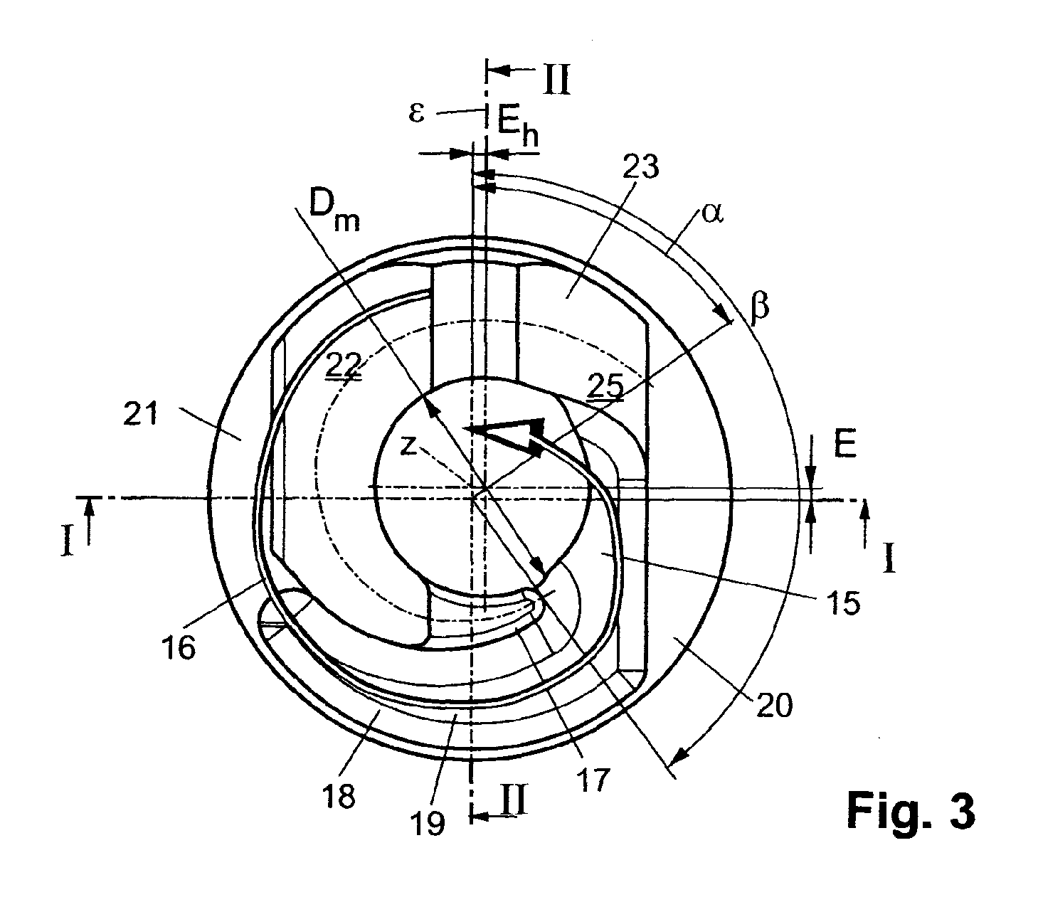
- the center of gravity z of the combustion chamber trough in the plane of the piston surface has an eccentricity E h to a reference plane ⁇ , for which the following applies: -0.12 * D ⁇ E h ⁇ 0.12 * D, the reference plane ⁇ being due to the Intersection line of the two roof-shaped boundary surfaces of the combustion chamber and the piston axis is defined and D is the piston diameter.
- the eccentricity E in the course of the piston axis parallel to the reference plane ⁇ can be between -0.03 * D and + 0.12 * D, a displacement of the combustion chamber trough which is carried out upwards in FIG. 3 preferably being advantageous.
- the inner flow guide surface of the guide rib to the piston axis has an angle ⁇ between -5 ° and 20 °. So there are undercuts the flow guide surface up to 20 ° provided to the mixture cloud in the combustion chamber trough to keep.
- a reciprocating piston 2 is arranged in a cylinder 1.
- the surface 3 of the Piston 2 forms together with the roof-shaped combustion chamber top surface in cylinder head 4 5 a combustion chamber 6, into which an ignition device 8 opens.
- the Mouth 10 of a fuel introduction device 9 is located at the edge of the combustion chamber 6.
- the longitudinal axis of the fuel delivery device 9 is designated 11, the Angle y between the longitudinal axis 1 1 and the plane of the cylinder head 4 is 25 to 60 °.
- the fuel introduction device 9 is arranged so that an injected fuel jet 12 is essentially directed towards the ignition device 8, and the fuel jet 12 approximately in the area of the combustion chamber trough 14 of the piston 2 strikes its surface 3.
- a reference plane ⁇ is introduced, which through the intersection of the two roof-shaped boundary surfaces of the Combustion chamber 6 and the piston axis 7 is spanned. (see Fig. 1 and Fig. 3).
- the swirl movement is on the piston surface 3 the asymmetrical, arch-shaped guide rib 13 supporting the cylinder charge is formed, which largely the roof-shaped boundary of the combustion chamber 6 in its outer contour is reproduced, and the essentially centrally shaped combustion chamber trough 14 and one Has trough inlet 15 located in the area of the fuel introduction device 9.
- the guide rib 13 has the direction of the swirl flow designated by 16 (see, for example, FIG. 3) end 17 tapering in width and height.
- the invention has the following features: Trough diameter D m 0.3 * D ⁇ D m ⁇ 0.6 * D Depth of the trough T m 0.1 * D ⁇ T m ⁇ 0.23 * D Depth below the crushing surface T uq 0.02 * D ⁇ T uq ⁇ 0.14 * D Width of the guide rib B 0.06 * D ⁇ B ⁇ 0.15 * D Eccentricity E -0.03 * D ⁇ E ⁇ + 0.12 * D Eccentricity E h -0.12 * D ⁇ E h ⁇ 0.12 * D Beginning of the ribs 20 ° ⁇ ⁇ 70 ° Guide rib end 120 ° ⁇ ⁇ 170 ° Inclination of the flow control surface -5 ° ⁇ ⁇ 20 °
- the data on the eccentricity refer to the center of gravity z of the combustion chamber bowl 14 in the plane of the piston surface 3.
- the combustion chamber trough 14 can also be in the be substantially circular.
- D is the piston diameter.
- the angle information in connection with the beginning 25 and the end 17 of the Guide ribs 13 are made clockwise around the piston axis, starting from the reference plane ⁇ 7 measured.
- the inner flow guide surface 13 ', which delimits the combustion chamber trough, can be inclined outwards ( ⁇ ⁇ 5 °) or inwards ( ⁇ ⁇ 20 °).
- the invention can be advantageous in terms of design variants with two, three, four or five valves per cylinder.
Landscapes
- Engineering & Computer Science (AREA)
- Chemical & Material Sciences (AREA)
- Combustion & Propulsion (AREA)
- Mechanical Engineering (AREA)
- General Engineering & Computer Science (AREA)
- Combustion Methods Of Internal-Combustion Engines (AREA)
Abstract
Bei einer Brennkraftmaschine mit Fremdzündung und zumindest einem hin- und hergehenden
Kolben (2), mit Zündeinrichtung (8) und mindestens einer Kraftstoffeinbringungseinrichtung
(9) pro Zylinder (1), sowie einem dachförmig begrenzten Brennraum (6), weist die
Oberfläche (3) des Kolbens (2) eine die Drallbewegung der Zylinderladung unterstützende,
asymmetrische, bogenförmige Leitrippe (13) auf. Die Leitrippe (13) wird durch eine Anformung
an der Kolbenoberfläche (3) gebildet, welche die dachförmige Begrenzung des Brennraumes
(6) weitgehend nachbildet, und eine im wesentlichen zentral ausgebildete Brennraummulde
(14) sowie einen im Bereich der Kraftstoffeinbringungseinrichtung (9) liegenden
Muldeneinlauf (15) ausweist.
Description
Die Erfindung betrifft eine Brcnnkraftmaschine mit Fremdzündung und zumindest einem hin- und hergehenden Kolben, mit einer Zündeinrichtung und mindestens einer Kraftstoffeinbringungseinrichtung pro Zylinder zur direkten Kraftstoffeinbringung im wesentlichen in Richtung Zündeinrichtung, sowie mit zumindest einem eine Drallströmung im dachförmig begrenzten Brennraum erzeugenden Einlaßkanal, wobei die Oberfläche des Kolbens eine die Drallbewegung der Zylinderladung unterstützende, asymmetrische, bogenförmige Leitrippe aufweist.The invention relates to an internal combustion engine with spark ignition and at least one rear and outgoing pistons, with an ignition device and at least one fuel introduction device per cylinder for direct fuel injection essentially in the direction Ignition device, and with at least one swirl flow in the roof-shaped limited Combustion chamber generating inlet channel, the surface of the piston one Swirl movement of the cylinder charge supporting, asymmetrical, arch-shaped guide rib having.
Ständig steigende Anforderungen an den Kraftstoffverbrauch und die Reduktion der Abgasemissionen, insbesondere der Kohlenwasserstoffe, erfordern den Einsatz neuer Technologien im Bereich der Verbrennungskraftmaschinen. Durch den heute üblichen Einsatz einer externen Gemischbildung bei Otto-Motoren, wie z.B. durch die Verwendung einer Saugrohreinspritzung oder eines Vergasers, strömt ein Teil des in den Brennraum und Zylinder eingesaugten Gemisches während der Ventilüberschneidungsphase, wenn Auslaß- und Einlaßventil gleichzeitig offen sind, in den Auspufftrakt der Brennkraftmaschine. Ein nicht unerheblicher Teil der meßbaren unverbrannten Kohlenwasserstoffe im Auspufftrakt stammt auch von Gemischteilen, die sich während der Verbrennung in Ringspalten oder wandnahen Bereichen, wo keine Verbrennung stattfindet, aufhalten. Zu diesen genannten Punkten kommt die notwendige Homogenisierung der Zylinderladung bei einem annähernd stöchiometrischen Mischungsverhältnis von Kraftstoff und Luft hinzu, welches eine sichere und aussetzerfreie Verbrennung sicherstellt. Dies bedingt eine Regelung der Motorlast mit Hilfe eines Drosselorganes zur Begrenzung der insgesamt angesaugten Gemischmenge (Quantitätsregelung).Constantly increasing demands on fuel consumption and the reduction of exhaust emissions, especially hydrocarbons, require the use of new technologies in the field of internal combustion engines. Through the usual use of an external one today Mixture formation in Otto engines, e.g. through the use of an intake manifold injection or a carburetor, flows a part of the sucked into the combustion chamber and cylinder Mixture during the valve overlap phase, when exhaust and intake valve are open at the same time in the exhaust tract of the internal combustion engine. A not inconsiderable one Part of the measurable unburned hydrocarbons in the exhaust tract also comes from mixture parts, which occur during combustion in annular gaps or areas close to the wall, where stop burning. The necessary points come to these points Homogenization of the cylinder charge with an approximately stoichiometric mixing ratio of fuel and air, which ensures safe and intermittent combustion ensures. This requires regulation of the engine load with the help of a throttle element to limit the total amount of mixture sucked in (quantity control).
Diese Drosselung der Ansaugströmung führt zu einem thermodynamischen Verlust, der den Kraftstoffverbrauch der Verbrennungskraftmaschine erhöht. Das Potential zur Verbrauchsreduzierung der Verbrennungskraftmaschine bei Umgehung dieser Drosselung kann auf etwa 20% geschätzt werden.This throttling of the intake flow leads to a thermodynamic loss that the Fuel consumption of the internal combustion engine increases. The potential for reducing consumption the internal combustion engine bypassing this throttling can be about 20% can be estimated.
Um diese Nachteile zu verhindern bzw. zu vermindern, werden schon seit langem Versuche unternommen, fremdgezündete Verbrennungskrafimaschinen ungedrosselt zu betreiben und den Kraftstoff erst nach Beendigung der Luftansaugung wie bei einer selbstzündenden Brennkraftmaschine innerhalb des Brennraums und Zylinders oder einer unmittelbar angeschlossenen Mischkammer einzubringen.Attempts have long been made to prevent or reduce these disadvantages undertaken to operate spark-ignited internal combustion engines unthrottled and the fuel only after the air intake has ended, as in a self-igniting internal combustion engine inside the combustion chamber and cylinder or one directly connected Introduce mixing chamber.
Dabci sind grundsätzlich drei Gcmischbildungssystemc zu unterscheiden:
- Flüssigkeitshochdruckeinspritzung
- Luftunterstützte Kraftstoff-Einbringung
- Gemischeinblasung.
- High pressure liquid injection
- Air-assisted fuel delivery
- Mixture injection.
Aus SAE 780699 ist ein Verfahren bekannt, bei dem der Kraftstoff mittels einer Hochdruckeinspritzdüse direkt in den Brennraum der Verbrennungskraftmaschine eingespritzt wird. Die notwendige Zeit für die Aufbereitung des Gemisches begrenzt den zeitlichen Minimalabstand zwischen Einspritzzeitpunkt und Zündzeitpunkt. Es ist ein hohes Druckniveau für den Einspritzvorgang notwendig, um einerseits kurze Einspritzzeiten und andererseits eine gute Zerstäubung des Kraftstoffes mit entsprechend kleinem Tropfenspektrum zu erhalten. Die Aufbereitung und Dosierung des Kraftstoffes findet gleichzeitig statt. Um nur ein örtlich begrenztes Gebiet mit brennbarem Kraftstoff-Luftgemisch zu erhalten ist es andererseits notwendig, erst sehr spät im Motorzyklus den Kraftstoff einzubringen (ggf. erst während der Kompression kurz vor der Zündung), um die Zeit für die Ausbreitung und Verdünnung des Gemisches in der Brennraumluft zu begrenzen. Die Forderungen nach genügend früher Einspritzung für vollständige Kraftstoffverdampfung und möglichst später Einspritzung zur Aufrechterhaltung der Gemischschichtung stehen daher im Gegensatz zueinander. Die Entwicklungsbemühungen müssen somit darauf gerichtet sein, einerseits die charakteristische Zeit für die Gemischaufbereitung zu verkürzen und andererseits die charakteristische Zcit der Aufrechterhaltung der gewünschten Gemisch-Schichtung zu verlängern.A method is known from SAE 780699 in which the fuel is produced by means of a high-pressure injection nozzle is injected directly into the combustion chamber of the internal combustion engine. The The time required for the preparation of the mixture limits the minimum time interval between injection timing and ignition timing. It is a high pressure level for the injection process necessary for short injection times on the one hand and good atomization on the other to obtain the fuel with a correspondingly small drop spectrum. The preparation and metering of the fuel takes place simultaneously. Just a local one On the other hand, it is necessary to maintain an area with a combustible air-fuel mixture first Introduce the fuel very late in the engine cycle (possibly only during compression shortly before ignition) to determine the time for the mixture to spread and dilute limit the combustion chamber air. The demands for early enough injection for complete fuel evaporation and later possible injection to maintain the mixture stratification is therefore in contrast to each other. The development effort must therefore be focused on the one hand the characteristic time for the mixture preparation to shorten and on the other hand the characteristic Zcit of maintaining to extend the desired mixture stratification.
Aus SAE 940188 ist das Prinzip eines Einspritzventils bekannt, welches einen kegelförmigen Einspritzstrahl mit hoher Zerstäubungsgüte des Kraftstoffes erzielt. Durch Änderung des Kraftstoffdruckes und des Brennraumgegendruckes kann der Kegelwinkel des Einspritzstrahls beeinflußt werden. Eine charakteristische Eigenschaft derartiger Einspritzdüsen ist die Verbesserung der Zerstäubungsgüte mit steigendem Einspritzdruck. Diese gewünschte Abhängigkeit führt jedoch zu ebenfalls steigenden Geschwindigkeiten des Einspritzstrahls von bis zu 100 m/s und somit zu einem hohen Impuls des in den Brennraum eintretenden Kraftstoff-Sprays. Demgegenüber weist die Luftströmung im Brennraum, selbst bei starker einlaßgenerierter Drall- oder Tumblebewegung mit maximal ca. 25 - 30 m/s nur einen deutlich geringeren Impuls auf, weshalb der Einspritzstrahl in einer ersten Phase des Eintritts in den Brennraum nur unwesentlich von der Brennraumströmung beeinflußt wird.The principle of an injection valve is known from SAE 940188, which is a conical one Injection jet achieved with high atomization quality of the fuel. By changing the Fuel pressure and the combustion chamber back pressure can be the cone angle of the injection jet to be influenced. A characteristic property of such injection nozzles is that Improvement of the atomization quality with increasing injection pressure. This desired dependency however, also leads to increasing speeds of the injection jet of up to 100 m / s and thus to a high impulse of the fuel spray entering the combustion chamber. In contrast, the air flow in the combustion chamber, even with strong intake-generated Twist or tumble movement with a maximum of approx. 25 - 30 m / s only a significantly lower one Impulse, which is why the injection jet in a first phase of entry into the Combustion chamber is only slightly influenced by the combustion chamber flow.
Es stellt sich unter diesen Voraussetzungen die Aufgabe, aus dem Einspritzstrahl eine örtlich begrenzte Gemischwolke zu erzeugen, diese von der Mündung des Einspritzventiles in die Nähe der Zündkerze zu transportieren und das Gemisch innerhalb der Wolke weiter mit Brennraumluft zu vermischen. Dabei sind folgende Punkte wesentlich :
- Die Gemischwolke muß insbesondere bei niedrigen Motorlasten deutlich abgegrenzt bleiben und sich aus thermodynamischen Gründen sowie zur Reduzierung der Emissionen unverbrannter Kohlenwasserstoffe möglichst in der Mitte des Brennraumes befinden.
- Die Verdünnung des eingeblasenen Gemisches auf ein vorzugsweise stöchiometrisches Luftverhältnis muß in der vergleichsweise kurzen Zeitspanne zwischen Einspritzzeitpunkt und Zündzeitpunkt erfolgen.
- An der Zündkerze sollte eine geringe mittlere Strömungsgeschwindigkeit und gleichzeitig ein hohes Turbulenzniveau herrschen, um die Entflammung der Gemischwolke durch den Zündfunken zu begünstigen.
- The mixture cloud must remain clearly delimited, especially at low engine loads, and must be located in the center of the combustion chamber for thermodynamic reasons and to reduce the emissions of unburned hydrocarbons.
- The dilution of the blown-in mixture to a preferably stoichiometric air ratio must take place in the comparatively short time span between the injection time and the ignition time.
- A low average flow velocity and at the same time a high level of turbulence should prevail at the spark plug in order to promote the ignition of the mixture cloud by the ignition spark.
Bei der Gestaltung eines geeigneten Brennverfahrens für einen direkteinspritzenden Ottomotor sind neben den Charakteristiken der Einspritzstrahlausbreitung auch die zur Verfügung stehenden Brennraumabmessungen zu berücksichtigen. Für PKW-Ottomotoren typische Hubräume des Einzelzylinders führen zu Bohrungsdurchmessern von ca. 65 bis 100 mm, wobei sich der Kolbenhub in der gleichen Größenordnung bewegt.When designing a suitable combustion process for a direct-injection gasoline engine In addition to the characteristics of the injection jet spread, those are also available standing combustion chamber dimensions. Typical displacement for car gasoline engines of the single cylinder lead to bore diameters of approx. 65 to 100 mm, whereby the piston stroke is of the same order of magnitude.
Bei einer Anordnung des Einspritzventils im Zylinderkopf in einer maximal ca. 70° zur Zylinderachse geneigten Position steht dem Einspritzstrahl im Falle einer späten Einspritzung kurz vor dem Zündzeitpunkt eine freie Ausbreitungsstrecke von max. 50 - 60 mm zu Verfügung, bevor der Einspritzstrahl auf die gegenüberliegende Brennraumwand (zumeist die Kolbenoberfläche) auftrifft. In Anbetracht der genannten Ausbreitungsgeschwindigkeiten des Einspritzstrahls muß daher ein Auftreffen zumindest eines Teils des Kraftstoff-Sprays auf der Kolbenoberfläche erwartet werden. Die Gestaltung der Brennrauminnenströmung sollte daher diesen Vorgang der Wandbenetzung berücksichtigen.If the injection valve is arranged in the cylinder head at a maximum of approximately 70 ° to the cylinder axis inclined position faces the injection jet in the event of late injection shortly before the ignition point, a free propagation distance of max. 50 - 60 mm available, before the injection jet onto the opposite combustion chamber wall (mostly the piston surface) hits. In view of the speeds of propagation mentioned The injection jet must therefore strike at least part of the fuel spray on the Piston surface are expected. The design of the internal combustion chamber flow should therefore take this process of wall wetting into account.
Zur Formung der Gemischwolke und zur Aufbereitung des Kraftstoff-Sprays können folgende Effekte genutzt werden :
- Umlenkung des hohen Impulses des Einspritzstrahls zur Zündkerze mit Hilfe der Kolbenoberfläche.
- Hoher Einspritzdruck zur Verbesserung der Zerstäubung und damit zur Beschleunigung der direkten Verdampfung des Kraftstoff-Sprays vor der Wandberührung.
- Erzeugung eines erhöhten Turbulenzniveaus im Bereich des Einspritzstrahls durch die Brennrauminnenströmung.
- Beschleunigung der Wandfilmverdampfung durch Erzeugung einer hohen Strömungsgeschwindigkeit am benetzten Bereich der Kolbenoberfläche.
- Redirection of the high impulse of the injection jet to the spark plug with the help of the piston surface.
- High injection pressure to improve atomization and thus to accelerate the direct evaporation of the fuel spray in front of the wall.
- Generation of an increased level of turbulence in the area of the injection jet through the internal flow of the combustion chamber.
- Acceleration of wall film evaporation by generating a high flow velocity at the wetted area of the piston surface.
Alle durch die Brennrauminnenströmung erzielbaren Maßnahmen setzen die Generierung eines hohen Ladungsbewegungsniveaus beim Einlaßvorgang voraus. Diese hohen Strömungsgeschwindigkeiten sollten möglichst lange während der Ansaug- und Kompressionsphase erhalten bleiben oder sogar während der Kompression verstärkt werden. Diese Forderung läßt sich am sinnvollsten durch eine einlaßgenerierte Drall- oder Tumblebewegung der Brennraumluft erreichen. Eine Drallbewegung (Rotation um die Zylinderachse) stellt die stabilste Strömungsstruktur in Zylinder dar, was zur geringsten Dissipation der Bewegungsenergie während der Kompression führt. Durch Ausbildung einer gegenüber dem Zylinderdurchmesser kleineren Kolbenmulde läßt sich während der Kompression aufgrund der Drallerhaltung eine Zunahme der Rotationsgeschwindigkeit des Drallwirbels erzielen.All measures that can be achieved by the internal flow of the combustion chamber set the generation a high level of charge movement during the intake process. These high flow rates should be as long as possible during the intake and compression phase are preserved or even amplified during compression. This requirement can be made most sensible by an inlet-generated swirl or tumble movement of the Reach combustion air. A swirl movement (rotation around the cylinder axis) represents the most stable Flow structure in cylinders represents the least dissipation of kinetic energy leads during compression. By forming one compared to the cylinder diameter smaller piston bowl can be during compression due to the twist maintenance achieve an increase in the rotational speed of the swirl vortex.
Ein einlaßgenerierter Tumblewirbel (Rotation um eine zur Kurbelwelle parallele Achse) zeigt einerseits eine Beschleunigung der Rotation durch die Verkleinerung der Querschnittsfläche während der Kompression. Andererseits ist der Tumblewirbel im Vergleich zum Drall instabiler und neigt zum Zerfall in komplexere Sekundärwirbel. In der Endphase der Kompression ist bei genügend flachem Ventilwinkcl (eines typischen Vierventil-Brennraums) ein starker Zerfall des Tumblewirbels in kleinere stochastisch verteilte Wirbel zu beobachten.An inlet generated tumble vortex (rotation about an axis parallel to the crankshaft) shows on the one hand an acceleration of the rotation by reducing the cross-sectional area during compression. On the other hand, the tumble vortex is more unstable than the swirl and tends to disintegrate into more complex secondary vertebrae. In the final stage of compression is a strong one with a sufficiently flat valve angle (a typical four-valve combustion chamber) The tumble vertebra decays into smaller stochastically distributed vertebrae.
Aus der AT 001 392 Ul ist eine Brennkraftmaschine mit Fremdzündung und zumindest einem hin- und hergehenden Kolben mit einer Kolbenmulde bekannt, welche die einlaßgenerierte Drallströmung bei der Aufwärtsbewegung des Kolbens beschleunigt. Die Kolbenmulde ist dabei asymmetrisch gestaltet und weist einen Einlaufbereich mit zunehmender Muldentiefe, einen Zentralbereich mit maximaler Muldentiefe und einen Auslaufbereich mit abnehmender Muldentiefe auf. Zwischen dem Auslaufbereich und dem Einlaufbereich ist auf der Seite einer Kraftstoffeinbringungseinrichtung eine keilförmige Einschnürung vorgesehen. Die Form der Kolbenmulde bewirkt, daß einerseits ein Auftreffen der Kraftstoffstrahlen in Richtung der mittig angeordneten Zündkerze umgelenkt wird, und andererseits die Fallströmung während der Kompression durch die Kolbenmuldenform derart umgelenkt und beschleunigt wird, so daß im Auftreffbereich der Kraftstoffstrahlen eine auf die Zündkerze gerichtete Strömung mit hoher Geschwindigkeit erreicht wird. Das Turbulenzniveau reicht allerdings nicht aus, um bei jeder Drehzahl eine sichere Entflammung des Kraftstoffes sicher zu stellen.AT 001 392 Ul is an internal combustion engine with spark ignition and at least one reciprocating piston known with a piston recess, which generates the inlet Swirl flow accelerates when the piston moves upwards. The piston bowl is designed asymmetrically and has an inlet area with increasing trough depth, a central area with maximum trough depth and a discharge area with decreasing Trough depth. Between the outlet area and the inlet area is on the A wedge-shaped constriction is provided on the side of a fuel introduction device. The Shape of the piston bowl causes on the one hand an impact of the fuel jets in Direction of the centrally located spark plug is deflected, and on the other hand, the falling flow thus deflected and accelerated during the compression by the piston bowl shape is so that in the area of impact of the fuel jets on the spark plug directional flow is achieved at high speed. The level of turbulence is enough however, not to ensure safe ignition of the fuel at any speed to deliver.
Aus der JP 7-102976 A ist eine Brennkraftmaschine der eingangs genannten Art mit einer einzigen bogenförmigen Leitrippe bekannt, welche die Drallströmung in den Bereich der mittig angeordneten Zündkerze lenkt. Der Kraftstoff wird dabei in einen von den konkaven Leitflächen der Leitrippen begrenzten, muldenförmigen Bereich der Kolbenstirnfläche durch eine am Rand des Brennraumdaches angeordnete Einspritzdüse eingespritzt. Durch die seitliche Einspritzung zur Zylinderachse hin werden die Kraftstoffteilchen allerdings über die Leitrippe hinweggeschleudert und in einen durch eine konvexe Leitfläche der Leitrippe und den Kolbenrand begrenzten Bereich abgelenkt. Die abgelenkten Kraftstoffteilchen müssen erst wieder durch die Drallströmung in den Bereich der Zündkerze geführt werden, wobei ein relativ langer, sich über einen Winkelbereich von mehr als 180° erstreckender Strömungsweg entlang des Kolbenrandes zurückgelegt werden muß. Dies bewirkt, daß die abgelenkten Kraftstoffteilchen erst zu einem relativ späten Zeitpunkt im Bereich der Zündkerze eintreffen und für die Entflammung des Gemisches nicht mehr zur Verfügung stehen. Dies wirkt sich nachteilig für die Kohlenwasserstoffemissionen und für den Kraftstoffverbrauch aus.From JP 7-102976 A is an internal combustion engine of the type mentioned with a single arcuate guide rib known, which the swirl flow in the area of centrally located spark plug steers. The fuel turns into one of the concave ones Guide surfaces of the guide ribs delimit the trough-shaped area of the piston end face an injection nozzle arranged at the edge of the combustion chamber roof is injected. Through the side However, the fuel particles are injected towards the cylinder axis via the guide rib flung away and into a through a convex guide surface of the guide rib and the Deflected piston rim limited area. The deflected fuel particles must first again through the swirl flow into the area of the spark plug, with a relatively long flow path extending over an angular range of more than 180 ° must be covered along the piston rim. This causes the deflected fuel particles arrive at the spark plug area at a relatively late point in time and are no longer available to ignite the mixture. This has an adverse effect for hydrocarbon emissions and for fuel consumption.
In der FR 2 421 276 Al wird ein Kolben mit einer turbulenzfördernd ausgebildeten Kolbenmulde
für eine fremdgezündete Brennkraftmaschine gezeigt. Die asymmetrisch gestaltete
Kolbenmulde weist drei verschieden große Einlaufbereiche auf, die in eine topfförmige
asymmetrische Vertiefung der Kolbenmulde einmünden. Durch die drei Einlaufbereiche wird
in der Vertiefung eine Drallströmung erzeugt.
Ferner ist aus der DE 649 738 C eine selbstzündende Viertakt-Brennkraftmaschine mit Schiebersteuerung und gegenüber dem Zylinderdurchmesser eingeschnürtem Brennraum bekannt. Der Kolben weist dabei in Richtung der Brennraumeinschnürung weisende Vertiefungen auf, welche die Strömung vom Einlaßbereich schraubenartig zum Brennraum lenkt. Für eine Brennkraftmaschine mit Fremdzündung und direkter Kraftstoffeinbringung ist diese Brennraumform nicht geeignet.Furthermore, DE 649 738 C describes a self-igniting four-stroke internal combustion engine with slide control and known compared to the cylinder diameter constricted combustion chamber. The piston has depressions pointing in the direction of the combustion chamber constriction, which directs the flow from the inlet area to the combustion chamber like a screw. For one Internal combustion engine with spark ignition and direct fuel injection is this Combustion chamber shape not suitable.
Aufgabe der vorliegenden Erfindung ist es, die genannten Nachteile zu vermeiden und die Zerstäubung und Entflammung des Kraftstoffes bei einer Brennkraftmaschine der eingangs genannten Art zu verbessern.The object of the present invention is to avoid the disadvantages mentioned and the Atomization and ignition of the fuel in an internal combustion engine at the beginning to improve the type mentioned.
Erfindungsgemäß wird dies dadurch erreicht, daß die Leitrippe durch eine Anformung an der Kolbenoberfläche gebildet ist, welche die dachförmige Begrenzung des Brennraumes weitgehend nachbildet, und eine im wesentlichen zentral ausgebildete Brennraummulde sowie einen im Bereich der Kraftstoffeinbringungseinrichtung liegenden Muldeneinlauf ausweist, sowie daß die Leitrippe in Richtung der Drallströmung ein sich in Breite und Höhe verjüngendes Ende aufweist. Aufgrund der Nachbildung des zylinderkopfseitigen Brennraumdaches, durch die auf der Kolbenoberfläche ausgebildete Leitrippe und einer nahezu zentral angeordneten, ausgeprägten Brennraummulde kommt es zu einem Zurückschieben der über die Brennraummulde und Leitrippe hinwegströmenden (vagabundierenden) Kraftstoffteilchen durch eine sich zwischen der Kolbenoberfläche und dem Brennraumdach ausbildenden Quetschströmung.According to the invention this is achieved in that the guide rib is formed on the Piston surface is formed, which largely the roof-shaped boundary of the combustion chamber reproduces, and an essentially centrally formed combustion chamber bowl as well identifies a trough inlet located in the area of the fuel introduction device, and that the guide rib tapering in width and height in the direction of the swirl flow End. Due to the replica of the cylinder head-side combustion chamber roof, due to the guide rib formed on the piston surface and an almost central, pronounced combustion chamber trough there is a pushing back of the Combustion chamber bowl and fins flowing away (stray) fuel particles through the formation between the piston surface and the combustion chamber roof Squeezing flow.
In einer vorteilhaften Ausgestaltung der Erfindung ist vorgesehen, daß ausgehend vom Muldeneinlauf ein um das sich verjüngende Ende der Leitrippe herumgeführter Muldenzulauf vorgesehen ist, welcher als in die Kolbenoberfläche eingearbeitete rinnenartige Vertiefung ausgeführt ist. Durch diese Maßnahme kommt es zu einer weiteren Beschleunigung der Drallströmung Richtung Muldeneinlauf, wobei die auslaßseitige Quetschströmung ausgenützt wird.In an advantageous embodiment of the invention it is provided that starting from the trough inlet a trough inlet led around the tapered end of the guide rib is provided, which as a groove-like recess machined into the piston surface is executed. This measure leads to a further acceleration of the swirl flow In the direction of the trough inlet, the squeezing flow on the outlet side being used.
In einer vorteilhaften Ausführungsvariante der Erfindung ist vorgesehen, daß an der Kolbenoberfläche einlaßseitige und auslaßseitige Quetschflächen ausgebildet sind, wobei die Leitrippe im Anschluß an diese Quetschflächen jeweils dachförmige Begrenzungsflächen aufweist, welche gegebenenfalls durch eine zur Kolbenoberfläche parallele Abflachung verbunden sind.In an advantageous embodiment of the invention it is provided that on the piston surface inlet-side and outlet-side squeeze surfaces are formed, the Guide rib in connection with these crushing surfaces, each roof-shaped boundary surfaces which is optionally connected by a flattening parallel to the piston surface are.
Erfindungsgemäß ist vorgesehen, daß der Flächenschwerpunkt z der Brennraummulde in der Ebene der Kolbenoberfläche zu einer Bezugsebene ε eine Exzentrizität Eh aufweist, für welche gilt -0,12*D < Eh < 0,12*D, wobei die Bezugsebene ε durch die Verschneidungslinie der beiden dachförmigen Begrenzungsflächen des Brennraumes und der Kolbenachse definiert ist und mit D der Kolbendurchmesser bezeichnet ist. Die Exzentrizität E im Bczug auf die Kolbenachse parallel zur Bezugsebene ε kann zwischen -0,03*D und +0,12*D liegen, wobei vorzugsweise eine Verschiebung der Brennraummulde von Vorteil ist, welche in Fig. 3 nach oben erfolgt.According to the invention, it is provided that the center of gravity z of the combustion chamber trough in the plane of the piston surface has an eccentricity E h to a reference plane ε, for which the following applies: -0.12 * D <E h <0.12 * D, the reference plane ε being due to the Intersection line of the two roof-shaped boundary surfaces of the combustion chamber and the piston axis is defined and D is the piston diameter. The eccentricity E in the course of the piston axis parallel to the reference plane ε can be between -0.03 * D and + 0.12 * D, a displacement of the combustion chamber trough which is carried out upwards in FIG. 3 preferably being advantageous.
Herstellungstechnische Vorteile ergeben sich insbesondere dann, wenn die Brennraummulde im wesentlichen kreisförmig ausgebildet ist.Manufacturing advantages arise especially when the combustion chamber trough is essentially circular.
Besondere Vorteile ergeben sich, wenn die innere Strömungsleitfläche der Leitrippe zur Kolbenachse einen Winkel δ zwischen -5° und 20° aufweist. Es sind somit Hinterschneidungen der Strömungsleitfläche bis zu 20° vorgesehen, um die Gemischwolke in der Brennraum-mulde zu halten.Particular advantages result when the inner flow guide surface of the guide rib to the piston axis has an angle δ between -5 ° and 20 °. So there are undercuts the flow guide surface up to 20 ° provided to the mixture cloud in the combustion chamber trough to keep.
Schließlich hat es sich als vorteilhaft erwiesen, wenn die Tiefe Tm der Brennraummulde größer ist als jene des rinnenartigen Muldenzulaufs.Finally, it has proven to be advantageous if the depth T m of the combustion chamber trough is greater than that of the channel-like trough inlet.
Die Erfindung wird anhand der Figuren näher erläutert. Es zeigen:
- Fig. 1
- die erfindungsgemäße Brennkraftmaschine in einem Längsschnitt nach der Linie 1-1 in Fig. 2 bzw. Fig. 3,
- Fig. 2
- einen Längsschnitt nach der Linie II-II in Fig. 1 bzw. Fig. 3,
- Fig. 3
- eine Draufsicht auf den Kolben der Brennkraftmaschine,
- Fig. 4
- einen Längsschnitt des Kolbens in einer Schnittführung gemäß Linie I-I in Fig. 2 bzw. Fig. 3,
- Fig. 5
- einen Längsschnitt des Kolbens in einer Schnittführung gemäß Linie II-II in Fig. 1 bzw. Fig. 3,
- Fig. 6
- eine Ausführungsvariante der erfindungsgemäßen Brennkraftmaschine mit einem Einlaß- und einem Auslaßventil,
- Fig. 7
- eine Variante mit zwei Einlaßventilen und einem Auslaßventil,
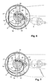
- Fig. 8
- eine Variante mit zwei Einlaßventilen und zwei Auslaßventilen sowie
- Fig. 9
- eine Variante mit drei Einlaßventilen und zwei Auslaßventilen pro Zylinder der Brennkraftmaschine.
- Fig. 1
- the internal combustion engine according to the invention in a longitudinal section along the line 1-1 in Fig. 2 or Fig. 3,
- Fig. 2
- 3 shows a longitudinal section along the line II-II in FIG. 1 or FIG. 3,
- Fig. 3
- a plan view of the piston of the internal combustion engine,
- Fig. 4
- 3 shows a longitudinal section of the piston in a section along line II in FIG. 2 or FIG. 3,
- Fig. 5
- 3 shows a longitudinal section of the piston in a section along line II-II in FIG. 1 or FIG. 3,
- Fig. 6
- 1 an embodiment variant of the internal combustion engine according to the invention with an inlet and an outlet valve,
- Fig. 7
- a variant with two inlet valves and one outlet valve,
- Fig. 8
- a variant with two inlet valves and two outlet valves as well
- Fig. 9
- a variant with three intake valves and two exhaust valves per cylinder of the internal combustion engine.
Funktionsgleiche Teile sind in den Ausführungsvarianten mit gleichen Bezugszeichen versehen.Functionally identical parts are provided with the same reference symbols in the design variants.
In einem Zylinder 1 ist ein hin- und hergehender Kolben 2 angeordnet. Die Oberfläche 3 des
Kolbens 2 bildet zusammen mit der im Zylinderkopf4 dachförmig ausgebildeten Brennraumdeckfläche
5 einen Brennraum 6 aus, in welchen eine Zündeinrcichtung 8 einmündet. Die
Mündung 10 einer Kraftstoffeinbringungseinrichtung 9 befindet sich am Rand des Brennraumes
6. Die Längsachse der Kraftstoffeinbringungseinrichtung 9 ist mit 11 bezeichnet, der
Winkel y zwischen der Längsachse 1 1 und der Ebene des Zylinderkopfes 4 beträgt 25 bis 60°.
Die Kraftstoffeinbringungseinrichtung 9 ist so angeordnet, daß ein eingespritzer Kraftstoffstrahl
12 im wesentlichen zur Zündeinrichtung 8 gerichtet ist, und der Kraftstoffstrahl 12
etwa im Bereich der Brennraummulde 14 des Kolben 2 auf dessen Oberfläche 3 auftrifft. Für
die folgenden Winkel- und Entfernungsangaben wird eine Bezugsebene ε eingeführt, welche
durch die Verschneidungslinie der beiden dachförmigen begrenzungsflächen des
Brennraum 6 und der Kolbenachse 7 aufgespannt wird. (siehe Fig. 1 bzw. Fig. 3).A
Wie aus den Figuren 1 bis 9 ersichtlich, ist an der Kolbenoberfläche 3 eine die Drallbewegung
der Zylinderladung unterstützende, asymmetrische, bogenförmige Leitrippe 13 angeformt,
welche in ihrer äußeren Kontur die dachförmige Begrenzung des Brennraum 6 weitgehend
nachbildet ist, und die im wesentlichen zentral ausgebildete Brennraummulde 14 sowie einen
im Bereich der Kraftstoffeinbringungseinrichtung 9 liegenden Muldeneinlauf 15 aufweist. In
Richtung der mit 16 bezeichneten Drallströmung (siehe z. B. Fig. 3) weist die Leitrippe 13 ein
sich in Breite und Höhe verjüngendes Ende 17 auf.As can be seen from FIGS. 1 to 9, the swirl movement is on the
Weiters ist ausgehend vom Muldeneinlauf 15 ein um das sich verjüngende Ende 17 der
Leitrippe 13 herumgeführter Muldenzulauf 18 vorgesehen, welcher als rinnenartige Vertiefung
19 in die Kolbenoberfläche 3 eingearbeitet ist.Furthermore, starting from the
Die ebenen Teile der Kolbenoberfläche 3 verbreitern sich einlaßseitig und auslaßseitig zu
Quetschflächen 20, 21, wobei die Leitrippe 13 im Anschluß an diese Quetschflächen jeweils
dachförmige Begrenzungsflächen 22, 23 aufweist, welche durch eine zur Kolbenoberfläche 3
parallele Abflachung 24 miteinander verbunden sein können.The flat parts of the
Wie inbesondere aus den Figuren 3 bis 5 ersichtlich weist die Erfindung folgende Merkmale
auf:
Die Angaben über die Exzentrizität beziehen sich auf den Flächenschwerpunkt z der Brennraummulde
14 in der Ebene der Kolbenoberfläche 3. Die Brennraummulde 14 kann auch im
wesentlichen kreisförmig ausgebildet sein. Mit D wird jeweils der Kolbendurchmesser bezeichnet.
Die Winkelangaben im Zusammenhang mit dem Anfang 25 und dem Ende 17 der
Leitrippe 13 werden ausgehend von der Bezugsebene ε im Uhrzeigersinn um die Kolbenachse
7 gemessen. Die innere Strömungsleitfläche 13', welche die Brennraummulde begrenzt,
kann nach außen (δ < 5°) oder nach innen (δ < 20°) geneigt sein.The data on the eccentricity refer to the center of gravity z of the
Wie aus den Figuren 6 bis 9 ersichtlich kann die Erfindung vorteilhaft auf Ausführungsvarianten mit zwei, drei, vier oder fünf Ventilen pro Zylinder angewandt werden.As can be seen from FIGS. 6 to 9, the invention can be advantageous in terms of design variants with two, three, four or five valves per cylinder.
Claims (12)
Applications Claiming Priority (3)
| Application Number | Priority Date | Filing Date | Title |
|---|---|---|---|
| AT532/97 | 1997-03-27 | ||
| AT53297 | 1997-03-27 | ||
| AT0053297U AT2378U1 (en) | 1997-08-28 | 1997-08-28 | INTERNAL COMBUSTION ENGINE |
Publications (3)
| Publication Number | Publication Date |
|---|---|
| EP0899432A2 true EP0899432A2 (en) | 1999-03-03 |
| EP0899432A3 EP0899432A3 (en) | 1999-12-22 |
| EP0899432B1 EP0899432B1 (en) | 2002-12-11 |
Family
ID=3493123
Family Applications (1)
| Application Number | Title | Priority Date | Filing Date |
|---|---|---|---|
| EP98890231A Expired - Lifetime EP0899432B1 (en) | 1997-08-28 | 1998-08-06 | Spark ignition internal combustion engine |
Country Status (5)
| Country | Link |
|---|---|
| US (1) | US5979399A (en) |
| EP (1) | EP0899432B1 (en) |
| JP (1) | JP3079427B2 (en) |
| AT (2) | AT2378U1 (en) |
| DE (1) | DE59806601D1 (en) |
Cited By (1)
| Publication number | Priority date | Publication date | Assignee | Title |
|---|---|---|---|---|
| DE19726683B4 (en) * | 1997-06-24 | 2009-03-19 | Iav Gmbh Ingenieurgesellschaft Auto Und Verkehr | Multi-cylinder gasoline engine with fuel injection into the combustion chamber and a method of operating the same |
Families Citing this family (24)
| Publication number | Priority date | Publication date | Assignee | Title |
|---|---|---|---|---|
| EP1739294A1 (en) * | 1997-05-20 | 2007-01-03 | Nissan Motor Co., Ltd. | Piston for a direct injection gasoline engine |
| US6223715B1 (en) * | 1998-03-23 | 2001-05-01 | Yamaha Hatsudoki Kabushiki Kaisha | Combustion chamber for direct injected engine |
| GB9821052D0 (en) * | 1998-09-28 | 1998-11-18 | Ricardo Consulting Eng | Direct injection gasoline engines |
| AT3751U1 (en) * | 1999-08-26 | 2000-07-25 | Avl List Gmbh | INTERNAL COMBUSTION ENGINE |
| DE10018777B4 (en) | 2000-04-15 | 2018-05-30 | Dr. Ing. H.C. F. Porsche Aktiengesellschaft | Internal combustion engine of the Ottobau type with direct injection |
| JP2002327622A (en) * | 2001-04-27 | 2002-11-15 | Unisia Jecs Corp | Internal combustion engine piston |
| JPWO2003029635A1 (en) * | 2001-09-17 | 2005-01-20 | 日産自動車株式会社 | Apparatus and method for forming a stratified mixture of an internal combustion engine |
| JP3931752B2 (en) * | 2002-07-12 | 2007-06-20 | トヨタ自動車株式会社 | INTERNAL COMBUSTION ENGINE FOR COMPRESSED IGNITION OF MIXED AIR AND CONTROL METHOD FOR INTERNAL COMBUSTION ENGINE |
| US20050183693A1 (en) * | 2004-02-25 | 2005-08-25 | Ford Global Technologies Llc | Method and apparatus for controlling operation of dual mode hcci engines |
| DE102004053049A1 (en) * | 2004-11-03 | 2006-05-04 | Daimlerchrysler Ag | Internal combustion engine with direct injection |
| US7240645B2 (en) * | 2005-10-28 | 2007-07-10 | Reisser Heinz-Gustav A | Internal combustion engine |
| US7647907B2 (en) | 2006-12-07 | 2010-01-19 | Contour Hardening, Inc. | Induction driven ignition system |
| US8424501B2 (en) * | 2006-12-07 | 2013-04-23 | Contour Hardening, Inc. | Induction driven ignition system |
| US7533643B2 (en) * | 2006-12-07 | 2009-05-19 | Contour Hardening, Inc. | Induction driven ignition system |
| KR20100049934A (en) * | 2008-11-04 | 2010-05-13 | 현대자동차주식회사 | Gasoline direct injection engine |
| DE102009026574A1 (en) * | 2009-05-29 | 2010-12-02 | Robert Bosch Gmbh | Internal-combustion engine i.e. gas engine, has laser ignition device comprising ignition laser with ignition point, where ignition point lies in region of combustion chamber, in which flow rate at time of ignition is low |
| KR101373805B1 (en) * | 2009-11-26 | 2014-03-12 | 기아자동차주식회사 | Gasoline direct injection engine |
| US9091199B2 (en) * | 2013-02-26 | 2015-07-28 | GM Global Technology Operations LLC | Combustion system for an engine having a swirl inducing combustion chamber |
| JP6264882B2 (en) * | 2013-12-26 | 2018-01-24 | トヨタ自動車株式会社 | Combustion chamber structure of a spark ignition internal combustion engine |
| JP2015124659A (en) * | 2013-12-26 | 2015-07-06 | トヨタ自動車株式会社 | Combustion chamber structure of spark ignition type internal combustion engine |
| US10422299B2 (en) * | 2016-04-21 | 2019-09-24 | Tenneco Inc. | Piston with asymmetric upper combustion surface and method of manufacture thereof |
| US9995203B2 (en) * | 2016-10-27 | 2018-06-12 | Caterpillar Inc. | Piston design for flow re-direction |
| CN108915646A (en) * | 2018-09-06 | 2018-11-30 | 李龙龙 | Gas transmission line multiphase flow drainage gas production tool |
| JP7180304B2 (en) * | 2018-11-16 | 2022-11-30 | マツダ株式会社 | engine combustion chamber structure |
Family Cites Families (11)
| Publication number | Priority date | Publication date | Assignee | Title |
|---|---|---|---|---|
| DE649738C (en) * | 1935-03-06 | 1937-09-04 | Alfred Buechi | Four-stroke internal combustion engine with slide control |
| DE1576001A1 (en) * | 1967-01-14 | 1970-05-21 | Daimler Benz Ag | Externally ignited internal combustion engine with stratified charge |
| FR2421276A1 (en) * | 1978-03-31 | 1979-10-26 | Chrysler France | IC engine with turbulence generator - has piston crown face formed with chamber from which extend tapering curved channels |
| JPS58501332A (en) * | 1981-08-13 | 1983-08-11 | マツセイ−フア−ガソン−パ−キンス リミテツド | internal combustion engine |
| US4446830A (en) * | 1983-01-10 | 1984-05-08 | Ford Motor Company | Method of operating an engine with a high heat of vaporization fuel |
| US4719884A (en) * | 1986-02-03 | 1988-01-19 | Kubota Ltd. | Combustion chamber with a domed auxiliary chamber for a spark-ignition engine |
| US5140958A (en) * | 1990-06-27 | 1992-08-25 | Toyota Jidosha Kabushiki Kaisha | Two-stroke engine |
| JPH07102976A (en) * | 1993-10-05 | 1995-04-18 | Toyota Motor Corp | In-cylinder injection spark ignition engine |
| US5775288A (en) * | 1995-08-17 | 1998-07-07 | Yamaha Hatsudoki Kabushiki Kaisha | Combustion chamber |
| AT1392U1 (en) * | 1996-05-30 | 1997-04-25 | Avl Verbrennungskraft Messtech | INTERNAL COMBUSTION ENGINE |
| JP3746344B2 (en) * | 1996-12-24 | 2006-02-15 | トヨタ自動車株式会社 | Combustion chamber structure of internal combustion engine |
-
1997
- 1997-08-28 AT AT0053297U patent/AT2378U1/en not_active IP Right Cessation
-
1998
- 1998-08-06 EP EP98890231A patent/EP0899432B1/en not_active Expired - Lifetime
- 1998-08-06 AT AT98890231T patent/ATE229616T1/en not_active IP Right Cessation
- 1998-08-06 DE DE59806601T patent/DE59806601D1/en not_active Expired - Lifetime
- 1998-08-27 US US09/141,315 patent/US5979399A/en not_active Expired - Fee Related
- 1998-08-28 JP JP10242388A patent/JP3079427B2/en not_active Expired - Fee Related
Cited By (1)
| Publication number | Priority date | Publication date | Assignee | Title |
|---|---|---|---|---|
| DE19726683B4 (en) * | 1997-06-24 | 2009-03-19 | Iav Gmbh Ingenieurgesellschaft Auto Und Verkehr | Multi-cylinder gasoline engine with fuel injection into the combustion chamber and a method of operating the same |
Also Published As
| Publication number | Publication date |
|---|---|
| US5979399A (en) | 1999-11-09 |
| EP0899432A3 (en) | 1999-12-22 |
| DE59806601D1 (en) | 2003-01-23 |
| JP3079427B2 (en) | 2000-08-21 |
| EP0899432B1 (en) | 2002-12-11 |
| ATE229616T1 (en) | 2002-12-15 |
| JPH11141399A (en) | 1999-05-25 |
| AT2378U1 (en) | 1998-09-25 |
Similar Documents
| Publication | Publication Date | Title |
|---|---|---|
| EP0899432B1 (en) | Spark ignition internal combustion engine | |
| DE19713028C2 (en) | Four-stroke internal combustion engine with spark ignition | |
| DE19713030C2 (en) | Four-stroke internal combustion engine with spark ignition | |
| DE19713029C2 (en) | Four-stroke internal combustion engine with spark ignition | |
| DE69717050T2 (en) | combustion chamber | |
| DE19804161C2 (en) | Four-stroke internal combustion engine | |
| DE10124750A1 (en) | Fuel injection system has injection valve in combustion chamber near inlet valve and facing cylinder wall and produces several fuel jets, at least one oriented tangentially near ignition plug | |
| EP1319822B9 (en) | Combustion engine with direct injection | |
| EP0909885B1 (en) | Combustion engine with spark ignition | |
| EP0897052B1 (en) | Spark ignition internal combustion engine | |
| EP1362996B1 (en) | Piston for a direct injected spark ignition combustion engine | |
| EP0741237B1 (en) | Spark ignited combustion engine | |
| DE69008131T2 (en) | Internal combustion engine. | |
| DE10041424C2 (en) | Internal combustion engine with spark ignition | |
| DE10354827A1 (en) | fuel injection system | |
| DE19838868C2 (en) | Internal combustion engine with spark ignition | |
| DE19621635A1 (en) | Diesel IC-engine cylinder head | |
| WO2004059154A1 (en) | Internal combustion engine having auto-ignition | |
| AT1392U1 (en) | INTERNAL COMBUSTION ENGINE | |
| DE10027452C2 (en) | Process for mixture formation with impact support in internal combustion engines with gasoline direct injection | |
| DE10106887A1 (en) | Direct-injection internal combustion engine with spark ignition and method for operating such an internal combustion engine | |
| DE4033822C2 (en) | Combustion chamber of a diesel engine with direct injection | |
| EP0881372B1 (en) | Four-stroke engine with controlled ignition and direct injection | |
| AT1562U1 (en) | FOUR-STROKE INTERNAL COMBUSTION ENGINE | |
| AT1564U1 (en) | FOUR-STROKE INTERNAL COMBUSTION ENGINE |
Legal Events
| Date | Code | Title | Description |
|---|---|---|---|
| PUAI | Public reference made under article 153(3) epc to a published international application that has entered the european phase |
Free format text: ORIGINAL CODE: 0009012 |
|
| AK | Designated contracting states |
Kind code of ref document: A2 Designated state(s): AT DE ES FR GB IT SE |
|
| AX | Request for extension of the european patent |
Free format text: AL;LT;LV;MK;RO;SI |
|
| PUAL | Search report despatched |
Free format text: ORIGINAL CODE: 0009013 |
|
| AK | Designated contracting states |
Kind code of ref document: A3 Designated state(s): AT BE CH CY DE DK ES FI FR GB GR IE IT LI LU MC NL PT SE |
|
| AX | Request for extension of the european patent |
Free format text: AL;LT;LV;MK;RO;SI |
|
| 17P | Request for examination filed |
Effective date: 20000114 |
|
| AKX | Designation fees paid |
Free format text: AT DE ES FR GB IT SE |
|
| GRAG | Despatch of communication of intention to grant |
Free format text: ORIGINAL CODE: EPIDOS AGRA |
|
| GRAG | Despatch of communication of intention to grant |
Free format text: ORIGINAL CODE: EPIDOS AGRA |
|
| GRAH | Despatch of communication of intention to grant a patent |
Free format text: ORIGINAL CODE: EPIDOS IGRA |
|
| 17Q | First examination report despatched |
Effective date: 20020603 |
|
| GRAH | Despatch of communication of intention to grant a patent |
Free format text: ORIGINAL CODE: EPIDOS IGRA |
|
| GRAA | (expected) grant |
Free format text: ORIGINAL CODE: 0009210 |
|
| AK | Designated contracting states |
Kind code of ref document: B1 Designated state(s): AT DE ES FR GB IT SE |
|
| PG25 | Lapsed in a contracting state [announced via postgrant information from national office to epo] |
Ref country code: GB Free format text: LAPSE BECAUSE OF FAILURE TO SUBMIT A TRANSLATION OF THE DESCRIPTION OR TO PAY THE FEE WITHIN THE PRESCRIBED TIME-LIMIT Effective date: 20021211 |
|
| REF | Corresponds to: |
Ref document number: 229616 Country of ref document: AT Date of ref document: 20021215 Kind code of ref document: T |
|
| REG | Reference to a national code |
Ref country code: GB Ref legal event code: FG4D Free format text: NOT ENGLISH |
|
| REF | Corresponds to: |
Ref document number: 59806601 Country of ref document: DE Date of ref document: 20030123 |
|
| PG25 | Lapsed in a contracting state [announced via postgrant information from national office to epo] |
Ref country code: SE Free format text: LAPSE BECAUSE OF FAILURE TO SUBMIT A TRANSLATION OF THE DESCRIPTION OR TO PAY THE FEE WITHIN THE PRESCRIBED TIME-LIMIT Effective date: 20030311 |
|
| GBV | Gb: ep patent (uk) treated as always having been void in accordance with gb section 77(7)/1977 [no translation filed] |
Effective date: 20021211 |
|
| PG25 | Lapsed in a contracting state [announced via postgrant information from national office to epo] |
Ref country code: ES Free format text: LAPSE BECAUSE OF FAILURE TO SUBMIT A TRANSLATION OF THE DESCRIPTION OR TO PAY THE FEE WITHIN THE PRESCRIBED TIME-LIMIT Effective date: 20030627 |
|
| PG25 | Lapsed in a contracting state [announced via postgrant information from national office to epo] |
Ref country code: AT Free format text: LAPSE BECAUSE OF NON-PAYMENT OF DUE FEES Effective date: 20030806 |
|
| ET | Fr: translation filed | ||
| PLBE | No opposition filed within time limit |
Free format text: ORIGINAL CODE: 0009261 |
|
| STAA | Information on the status of an ep patent application or granted ep patent |
Free format text: STATUS: NO OPPOSITION FILED WITHIN TIME LIMIT |
|
| 26N | No opposition filed |
Effective date: 20030912 |
|
| PGFP | Annual fee paid to national office [announced via postgrant information from national office to epo] |
Ref country code: IT Payment date: 20080826 Year of fee payment: 11 Ref country code: FR Payment date: 20080828 Year of fee payment: 11 |
|
| REG | Reference to a national code |
Ref country code: FR Ref legal event code: ST Effective date: 20100430 |
|
| PG25 | Lapsed in a contracting state [announced via postgrant information from national office to epo] |
Ref country code: FR Free format text: LAPSE BECAUSE OF NON-PAYMENT OF DUE FEES Effective date: 20090831 |
|
| PG25 | Lapsed in a contracting state [announced via postgrant information from national office to epo] |
Ref country code: IT Free format text: LAPSE BECAUSE OF NON-PAYMENT OF DUE FEES Effective date: 20090806 |
|
| PGFP | Annual fee paid to national office [announced via postgrant information from national office to epo] |
Ref country code: DE Payment date: 20131002 Year of fee payment: 16 |
|
| REG | Reference to a national code |
Ref country code: DE Ref legal event code: R119 Ref document number: 59806601 Country of ref document: DE |
|
| REG | Reference to a national code |
Ref country code: DE Ref legal event code: R119 Ref document number: 59806601 Country of ref document: DE Effective date: 20150303 |
|
| PG25 | Lapsed in a contracting state [announced via postgrant information from national office to epo] |
Ref country code: DE Free format text: LAPSE BECAUSE OF NON-PAYMENT OF DUE FEES Effective date: 20150303 |