EP0898016B1 - Verfahren und Vorrichtung zum Transportieren eines Gleisabschnitts - Google Patents
Verfahren und Vorrichtung zum Transportieren eines Gleisabschnitts Download PDFInfo
- Publication number
- EP0898016B1 EP0898016B1 EP98114517A EP98114517A EP0898016B1 EP 0898016 B1 EP0898016 B1 EP 0898016B1 EP 98114517 A EP98114517 A EP 98114517A EP 98114517 A EP98114517 A EP 98114517A EP 0898016 B1 EP0898016 B1 EP 0898016B1
- Authority
- EP
- European Patent Office
- Prior art keywords
- track
- frame
- frame legs
- auxiliary
- gantry crane
- Prior art date
- Legal status (The legal status is an assumption and is not a legal conclusion. Google has not performed a legal analysis and makes no representation as to the accuracy of the status listed.)
- Expired - Lifetime
Links
- 238000000034 method Methods 0.000 title claims description 15
- 238000009434 installation Methods 0.000 claims description 19
- 230000000284 resting effect Effects 0.000 claims 2
- 230000000149 penetrating effect Effects 0.000 claims 1
- 210000002414 leg Anatomy 0.000 description 60
- 230000032258 transport Effects 0.000 description 15
- 125000006850 spacer group Chemical group 0.000 description 7
- 238000010276 construction Methods 0.000 description 3
- 210000000689 upper leg Anatomy 0.000 description 3
- XEEYBQQBJWHFJM-UHFFFAOYSA-N Iron Chemical compound [Fe] XEEYBQQBJWHFJM-UHFFFAOYSA-N 0.000 description 1
- 150000001875 compounds Chemical class 0.000 description 1
- 238000006073 displacement reaction Methods 0.000 description 1
- 238000005553 drilling Methods 0.000 description 1
- 238000004519 manufacturing process Methods 0.000 description 1
- 230000001360 synchronised effect Effects 0.000 description 1
Images





Classifications
-
- E—FIXED CONSTRUCTIONS
- E01—CONSTRUCTION OF ROADS, RAILWAYS, OR BRIDGES
- E01B—PERMANENT WAY; PERMANENT-WAY TOOLS; MACHINES FOR MAKING RAILWAYS OF ALL KINDS
- E01B23/00—Easily dismountable or movable tracks, e.g. temporary railways; Details specially adapted therefor
-
- E—FIXED CONSTRUCTIONS
- E01—CONSTRUCTION OF ROADS, RAILWAYS, OR BRIDGES
- E01B—PERMANENT WAY; PERMANENT-WAY TOOLS; MACHINES FOR MAKING RAILWAYS OF ALL KINDS
- E01B23/00—Easily dismountable or movable tracks, e.g. temporary railways; Details specially adapted therefor
- E01B23/10—Shiftable tracks for heavy loads, e.g. carrying excavators
- E01B23/14—Fastening or joining means
-
- E—FIXED CONSTRUCTIONS
- E01—CONSTRUCTION OF ROADS, RAILWAYS, OR BRIDGES
- E01B—PERMANENT WAY; PERMANENT-WAY TOOLS; MACHINES FOR MAKING RAILWAYS OF ALL KINDS
- E01B29/00—Laying, rebuilding, or taking-up tracks; Tools or machines therefor
- E01B29/02—Transporting, laying, removing, or renewing lengths of assembled track, assembled switches, or assembled crossings
Definitions
- the invention relates to a method for transporting a track section, in particular switch, crossing or frog area, to a laying site, wherein the Track section on at least a first dolly on a standard track in the Near the installation site is transported and then by means of cranes from the trolley in turn, with the track section on an auxiliary track to the laying site be moved to finally lower the track section and install.
- the invention relates to a device for transporting a track section to a laying site, wherein the track section optionally via a traverse raised by at least two cranes of at least a first trolley and is movable on an auxiliary track to the installation site.
- Switches mounted on sleepers are often moved from a manufacturing site to a laying site transported by rail-bound vehicles and then relocated. According to the state Technically, a corresponding track section is supported by a traverse and by means of this transported. At the place of installation, the track section can be transferred to auxiliary traverses and then discontinued and installed by means of this.
- a track of a traverse is hanging on a chassis supportable, which is movable on a track.
- the chassis itself is in turn by means of a caterpillar, which is movable next to the track, can be raised and lowered.
- DE 29 28 152 relates to a device for receiving or laying of Track switches and crossings. It also a tracked vehicle is used, which in desired circumference is rotatable to the track longitudinal axis.
- US 5,127,335 provides for laying intersections and points caterpillars, which is an integral part of a traverse which carries the track part to be laid.
- FR 2 561 275 relates to a device for laying a rail part, wherein a Wheel-supported vehicle is used which extends to both sides of the rails supported the track.
- the present invention is based on the problem, a method and an apparatus of the aforementioned type so that with structurally simple measures also in terms of area, especially in terms of width large track sections are laid can, possibly also high load bearing cranes are used, the easily on both standard tracks and on the auxiliary track are movable.
- the problem is essentially solved by the fact that cranes are gantry cranes used during their transport on the standard track with folded Frame legs transported on at least a second transport vehicle such be that in the process on the auxiliary track in a transverse to its longitudinal direction extending plane supporting frame legs in the longitudinal direction of the standard track be aligned, that for placing the gantry crane on the auxiliary track this first by means of one of the second. Dolly lifted outgoing lifting device and then rotated 90 ° or about 90 °, the frame legs in a circumference be unfolded that they are positioned on the auxiliary track, and then that the gantry crane positioned to the track section, lifted the track section and by means of the crane is transported to the installation site and lowered there. It should be before the Position the gantry crane to the track section of the gantry crane with it on the auxiliary track supporting frame legs continue to be raised until the frame legs forming sections aligned with each other to the required extent and then secured become.
- gantry cranes for receiving the track section of the first dolly and for transfer to the auxiliary track over which the track section transports to the installation site is used, gantry cranes that transported as the track section on dolly without the need for separate tracks; because of the collapsible legs as well as aligning the gantry during transport on the standard track the permissible space profile of a standard track is not exceeded, so that a usual Transportation can be done. Only when the gantry crane is to be transferred to the auxiliary track, whose track is considerably wider than that of the standard track, there is a turning of the gantry crane and unfolding its legs, so that the gantry crane over the to be laid Track section can be moved to lift the track section and the installation site to be able to transport.
- the track section is preferably directly on or via a traverse stored first dolly, so that the gantry cranes themselves to secure the track section do not need to be used.
- the gantry crane turns 90 ° and unfolds the frame legs supported on the auxiliary track or its rails, takes place until complete Aligning the gantry load distribution over both of the second dolly outgoing lifting device, which is preferably a scissor lift as well as the auxiliary track itself, so that the former dimensioned accordingly can be.
- the second dolly outgoing lifting device which is preferably a scissor lift as well as the auxiliary track itself, so that the former dimensioned accordingly can be.
- the portal crane itself will be along the auxiliary track via motor-driven wheel elements supported, so that a problem-free and accurate procedure is possible. It can the Portal crane remotely controlled to be movable on the auxiliary track.
- two associated gantry cranes for transporting a track section such can be controlled, that the first gantry crane via a first remote control and the second Portal crane operated via a second remote control, with the second remote control is convertible so that both the first and the second gantry crane operable synchronously are.
- the invention is characterized in that the cranes with gantry cranes during transport on at least a second. Dolly folded up, from A frame frame outgoing frame legs are that each gantry crane on the second Transport trolley is mounted on a lifting device that extends around a vertical Axis for aligning during transport in a longitudinal direction of the track Level arranged frame legs in a direction transverse to the longitudinal direction plane is formed rotatable. This is preferably in the lifting device to a lift table, in particular scissor lift, which raises by means of spindle drive or is lowerable.
- the teaching of the invention is a high load receiving with simple measures and on track wide track movable gantry crane for laying a track section usable, the gantry crane itself being common on standard railroads and does not exceed permissible room profiles.
- the gantry crane on the one hand collapsible Frame legs and on the other hand on a turning and lifting device the second dolly is supported on the standard track during the procedure, turned to align or park on an auxiliary track to the required extent and to be raised.
- the lifting table itself is preferably rotatable by means of a turntable formed, which starts from a dolly-side frame or a base plate, the or over the trolley bottom passing through elements such as bolts non-rotatable is arranged on the trolley.
- the required counter forces also recorded for turning the gantry crane.
- the Frame or the base plate on dolly edge side brackets on the trolley self-assured. These may be U-shaped brackets that are themselves on the one hand above the frame or the base plate and on the other hand below the Cargo bed of the trolley extend.
- the gantry crane a trolley has, which is movable by means of a rack and pinion drive.
- each one is connected via a joint Sections consists, each hinge leg outer side in a plane that at arranged on the auxiliary track gantry crane runs transversely to the longitudinal direction of the auxiliary track. This makes it possible, the gantry crane initially with in the track direction to the outside angled frame leg sections like thighs on the auxiliary track during lifting so that when lifting the gantry crane a load distribution between Lifting table and auxiliary track itself done.
- each frame leg on the end via motor-driven wheels supported by the auxiliary track, it goes without saying that only a few the wheels are motor driven.
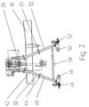
- the gantry cranes 18, 20 according to the invention of a Hochrahmen 26 outgoing frame legs 28, 30, 32, 34, each of at least two mutually pivotable portions, an outer portion 36, 40 and one of the high frame 26 outgoing inner portion 38, 42 are composed.
- the sections 36, 38, 40, 42 via a hinge 44, 45, joint or equivalent element connected.
- the sections 36, 38, 40, 42 are hinged outwards.
- the high frame 26 are raised in a circumference and rotated by preferably 90 °, that the on a trolley supporting inner portions 38, 42 are free and the outer portions 36, 40 can be pivoted to in the manner described below placed on the auxiliary track or its rails 22, 24 and then raised again to be until the frame legs 26, 28, 30, 32 and their sections 36, 38, 40, 42 in required extent aligned to each other.
- the frame 26 can not over illustrated telescopic devices such as stamp, which emanate from the high frame 26 can, or a lifting table (Fig. 5, 6) are raised.
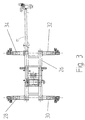
- two wheels 46, 48 and 50, 52 go from each outer section 36, 40 of the frame legs 28, 30, 32, 34, wherein at least one of the wheels 46, 52 by means of a motor is driven to move the gantry cranes 18, 20 along the auxiliary track to can.
- auxiliary track level frame legs 30, 32 and 28, 34 connected via longitudinal struts 58, which when folded Frame legs 28, 30, 32, 34 are removed.
- FIGS. 5 and 6 are further features to be emphasized and embodying the invention for elements described in connection with FIGS. 1 to 3 have been used, basically the same reference numerals.
- a lifting table 62 is carried along by a transporting carriage 60 Scissor arms 64, 66 to the frame 26 and thus the gantry crane in the required To be able to lift and turn the circumference.
- the lifting table 62 is on a turntable 68 supported, via a base plate or a base frame 70 with the trolley 60 is connected. In this case go from the base frame or the base plate 70 bolts from that pass through the loading surface 72 of the trolley 60, whereby the required Drehêt is given.
- the scissor arms 64, 66 which are interconnected centrally via an axis 67, are on the one hand on a base plate 74 of the lifting table 62 and on the other hand on the high frame 26th hinged. This is indicated by the reference numerals 76 and 78.
- the scissor arm 64 is with its free end 80 along a guide rail 82 of the lifting table 62 slidably. Accordingly, the scissor arm 66 with its free end 84 along a guide rail 86, which emanates from the high frame 26.
- a spindle drive 88 is attached, which in the embodiment of Attachment of the scissor arm 66 goes out.
- the scissor arm 64 a Fixed lock nut, which is interspersed by the spindle of the spindle drive 88 in accordance with the direction of rotation of the spindle 88, the scissor arms 64, 66 along the guide rails 82, 86 to method. Accordingly, the high frame 26 and thus the gantry crane is raised or lowered.
- a trolley 90 by means of a rack and pinion drive traversable.
- a rack is arranged on the high frame 26, with the a gear driven by the trolley 90 via a motor 92 meshes.
- a cable drum 101 runs in the region of an end face of the high frame 26, a cable drum 101, which in turn can be actuated via a motor 102.
- the high frame 26 is first by means of the lifting table 62 by Actuating the spindle drive 88 raised to an extent that the gantry crane to the Loading surface 72 of the trolley 60 is spaced in a circumference that the lifting table 62 can be rotated by 90 ° by means of the turntable 68.
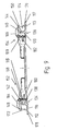
- FIGS. 7 to 12 an auxiliary track 110 zuent Spotify, along which a crane movable is that has a construction as described above. With one or several corresponding cranes can then a track section such as section of a switch Move to a place of installation and installed there.
- the auxiliary track 110 which includes the rails 22, 24, must be excessive in track width be exactly misplaced. To ensure this with simple measures, at the same time the Possibility should be given to quickly build up or dismantle the track 110, The following measures are planned.
- Each rail 22, 24 is at least partially arranged in brackets 112, 113 stationary.
- Each holder 112, 113 consists of an L or U-profile, from the bottom 116th Bolts go out 118, via the possibly via an intermediate layer 119 a ribbed plate 120 is fastened, on which the rail 22, 24 by means of clamping clamps 122, 124 fastened is.
- clamping clamps 122, 124 fastened is fastened, on which the rail 22, 24 by means of clamping clamps 122, 124 fastened is.
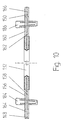
- lane keepers 126, 128, 130 are provided, which in Periodically connect the brackets 112, 113 with each other.
- each tracking device has a spacer 132, whose respective End has a designed as a step 134, 136 rectangular recess, wherein a in the graphic representation of vertically extending legs 138, 140 along the outside of the inner leg 142, 144 of the holder 112, 113 extends. Above the Leg 142, 144 preferably extends perpendicular to leg 138, 140 extending portion 148, 150 of the steps 134, 136, on the longitudinal edge of the leg 142, 144 supported with proper positioning of the tracking device 126, 128, 130 is.
- Each spacer element 132 is fork-shaped in its end region 152, 154 Accordingly, two parallel in side view L-shaped legs 156, 158 and 160, 162, wherein the respective horizontal leg of the section 148 and 150 is.
- the U- or claw-shaped element 164, 166 has a extending along the bottom or transverse leg 116, 117 extending portion 172, 174, with a projection 176, 178 when properly positioned below the foot 181 of the rail 22, 24 runs.
- the clear width of the recess 168, 170 of the element 164, 166 is wider than the thickness of the side leg 142, 144, as can be seen from the drawing.
- the wedge elements 184, 186 can each be secured by means of spring plugs 188, 187, unless they are self-locking fixed in the slots 180, 182.
- the horizontal runs between the free ends extending legs 148, 150 of the fork-shaped ends of the spacer element 132 and the nose-shaped projection 176, 178 of the claw-shaped element 164, 166 a Free space within which the rail foot 181 can extend with its longitudinal edge.
- the rail 22, 24 is fixedly secured in the holder 112, 113, thereby takes a Securing the lane keeping device.
- the tabs 196, 198 in the region of the respective rail section 188, 190 have elongated holes 210, 212, which corresponding slots in the Webs 192, 194 of the rail sections 188, 190 are associated overlapping.
- 190 partially overlapping slots now each wedge element 214 and 216 pushed, creating a relative displacement between the tabs 196 and 198 and the rail sections 188, 190 such that the abutting surfaces of the sections 188, 190 come to rest on each other, so that a gap between the rail sections 188, 190 does not form.
- the wedge elements 214, 216 may - like the wedge elements 184, 186 for securing the Lane keepers - be secured by spring plugs in the narrow range of Wedge members 214, 216 are supported on the outer surface of the tab 198, provided that Wedge elements 214, 216 are not self-locking positioned.
- Due to the features of the invention is a simple mounting or dismounting the Rails 22, 24 possible, while ensuring that the required track is complied with.
Landscapes
- Engineering & Computer Science (AREA)
- Architecture (AREA)
- Civil Engineering (AREA)
- Structural Engineering (AREA)
- Mechanical Engineering (AREA)
- Leg Units, Guards, And Driving Tracks Of Cranes (AREA)
- Machines For Laying And Maintaining Railways (AREA)
- Traffic Control Systems (AREA)
- Magnetic Heads (AREA)
- Intermediate Stations On Conveyors (AREA)
- Platform Screen Doors And Railroad Systems (AREA)
- Pusher Or Impeller Conveyors (AREA)
- Devices For Checking Fares Or Tickets At Control Points (AREA)
- Jib Cranes (AREA)
Description
- Fig. 1
- eine Vorderansicht einer ersten Ausführungsform eines Portalkrans zum Verlegen eines Gleisabschnitts,
- Fig.2
- eine Seitenansicht des Portalkrans nach Fig. 1,
- Fig. 3
- eine Draufsicht des Portalkrans nach Fig. 1 und 2,
- Fig. 4
- eine Seitenansicht einer von zwei Portalkränen zu einem Verlegeort transportierbaren Traverse mit an dieser befestigtem Gleisabschnitt,
- Fig. 5
- eine Seitenansicht einer zweiten Ausführungsform eines Portalkrans in auf ein Hilfsgleis ausgerichteter-Position,
- Fig. 6
- der Portalkran nach Fig. 5 in auf dem Hilfsgleis abgestützter Position,
- Fig. 7
- einen Ausschnitt eines Hilfsgleises,
- Fig. 8
- einen Schnitt entlang der Linie AA in Fig. 7,
- Fig. 9
- eine Spurhalteeinrichtung für das Hilfsgleis gemäß Fig. 7 in Seitenansicht,
- Fig. 10
- die Spurhalteeinrichtung nach Fig. 9 in Draufsicht,
- Fig. 11
- in Draufsicht auf Stoß miteinander verbundene Schienenabschnittedes Hilfsgleises gemäß Fig. 7 und
- Fig. 12
- eine Lasche der Verbindung gemäß Fig. 11.
- 10
- Traverse
- 12
- Gleisabschnitt
- 14, 16
- Schienen (Standardgleis)
- 18, 20
- Portalkräne
- 22, 24
- Schienen (Hilfsgleis)
- 26
- Hochrahmen
- 28, 30, 32, 34
- Rahmenbeine
- 36, 40
- äußerer Abschnitt der Rahmenbeine
- 38, 42
- innerer Abschnitt der Rahmenbeine
- 44, 45
- Scharnier
- 46, 48, 50, 52
- Laufräder
- 54, 56
- Teleskopstreben
- 58
- Längsstreben
- 60
- Transportwagen
- 62
- Hubtisch
- 64, 66.
- Scherenarme
- 67
- Achse
- 68
- Drehkranz
- 70
- Grundrahmen
- 72
- Ladefläche des Transportwagens
- 74
- Basisplatte
- 76, 78
- Anlenkpunkte
- 80
- freies Ende des Scherenarms 64
- 82
- Führungsschiene
- 84
- freies Ende des Scherenarms 66
- 86
- Führungsschiene
- 88
- Spindelantrieb
- 90
- Laufkatze
- 92
- Motor
- 94, 96
- galgenförmige Halterungen
- 98, 100
- Hebezüge
- 101
- Kabeltrommel
- 102
- Motor
- 110
- Hilfsgleis
- 112, 113
- Halterungen
- 1 16
- Boden
- 118
- Schrauben
- 119
- Zwischenlage
- 120
- Rippenplatte
- 122, 124
- Spannklemmen
- 126, 128, 130
- Spurhalteeinrichtungen
- 132
- Abstandselement
- 134, 136
- Stufe
- 138, 140
- vertikaler Schenkel
- 142, 144
- innenliegender Schenkel der Halterung 112, 113
- 148, 150
- Abschnitt
- 152, 154
- Endbereiche
- 156, 158, 160, 162
- L-förmiger Schenkel
- 164, 166
- klauenförmiges Element
- 168, 170
- Aussparung
- 172, 174
- Abschnitt
- 176, 178
- Vorsprung
- 181
- Fuß
- 180, 182
- Längsschlitze
- 184, 186
- Keilelemente
- 185, 187
- Federstecker
- 188, 190
- Abschnitte der Schienen 22, 24
- 192, 194
- Stege
- 196, 198
- Laschen
- 200, 202, 204, 206
- Bohrungen
- 208
- Schraube
- 210, 212
- Langlöcher
- 214, 216
- Keilelement
Claims (14)
- Verfahren zum Transportieren eines Gleisabschnitts (12), insbesondere Weiche, Kreuzung oder Herzstückbereich, zu einem Verlegeort, wobei der Gleisabschnitt auf zumindest einem ersten Transportwagen auf einem Standardgleis bis in die Nähe des Verlegeortes transportiert wird und sodann mittels Kränen (18, 20) von dem Transportwagen angehoben wird, die ihrerseits mit dem Gleisabschnitt auf einem Verlegeben wird, die ihrerseits mit dem Gleisabschnitt auf einem Hilfsgleis (110) zu dem Verlegeort verfahren werden, um schließlich den Gleisabschnitt abzusenken und einzubauen,
dadurch gekennzeichnet, dass als Kräne Portalkrane (18, 20) verwendet werden, die während ihres Transportes auf dem Standardgleis mit zusammengeklappten Rahmenbeinen (28, 30, 32, 34) aut zumindest einem zweiten Transportwagen derart transportiert werden, dass die beim Verfahren auf dem Hilfsgleis in einer quer zu dessen Längsrichtung verlaufenden Ebene sich abstützenden Rahmenbeine in Längsrichtung des Standardgleises ausgerichtet werden, dass zum Aufsetzen des Portalkrans auf das Hilfsgleis (110) dieser bei weiterhin zusammengeklappten Rahmenbeinen zunächst mittels einer von dem zweiten Transportwagen ausgehenden Hebeeinrichtung angehoben und gedreht, sodann die Rahmenbeine ausgeklappt und auf dem Hilfsgleis positioniert werden und dass anschließend der Kran zu dem zu transportierenden Gleisabschnitt positioniert, der Gleisabschnitt angehoben und mittels des Krans zum Verlegeort transportiert und dort abgesenkt wird. - Verfahren nach Anspruch 1,
dadurch gekennzeichnet, dass der Portalkran (18, 20) bei sich auf dem Hilfsgleis (110) angerichteten und sich auf diesem abstützenden Rahmenbeinen (28, 30, 32, 34) weiter angehoben wird, bis dass die Rahmenbeine bildende Abschnitte (36, 30, 40, 42) in erforderlichem Umfang zueinander ausgerichtet sind und sodann gesichert werden. - Verfahren nach Anspruch 1 oder 2,
dadurch gekennzeichnet, dass der Portalkran (18, 20) über motorangetriebene Radelemente (46, 52) auf dem Hilfsgleis abgestützt wird und/oder ferngesteuert auf dem Hilfsgleis (110) verfahren wird. - Verfahren nach zumindest einem der vorhergehenden Ansprüche,
dadurch gekennzeichnet, dass zwei einander zugeordnete Portalkräne (18, 20) zum Transportieren eines Gleisabschnitts (12) derart ansteuerbar sind, dass ein erster Portalkran über eine erste Fernsteuerung und der zweite Portalkran über eine zweite Fernsteuerung unabhängig voneinander betätigt werden, wobei die zweite Fernsteuerung derart umstellbar ist, dass der erste und der zweite Portalkran über die zweite Fernsteuerung synchron betätigt werden. - Vorrichtung zum Transportieren eines Gleisabschnittes (12) zu einem Verlegeort, wobei der Gleisabschnitt vorzugsweise über eine Traverse (10) mittels zumindest zweier Kränen (18, 20) von zumindest einem ersten Transportwagen anhebbar und auf einem Hilfsgleis (22, 24) zu dem verlegeort verfahrbar ist,
dadurch gekennzeichnet, dass die Kräne (18, 20) Portalkräne mit beim Transport auf zumindest einem zweiten Transportwagen (60) angeordneten zusammengeklappten von einem Hochrahmen ausgehenden Rahmenbeinen (28, 30; 32, 34) sind, dass jeder Portalkran auf dem zumindest zweiten Transportwagen auf einer Hebevorrichtung (62) befestigt ist, die um eine vertikal verlaufende Achse zum Ausrichten von beim Transport in eine in Längsrichtung des Standardgleises verlaufenden Ebene angeordnete Rahmenbeine (30, 32; 28, 34) in eine quer zur Längsrichtung verlaufende Ebene drehbar ausgebildet ist. - Vorrichtung nach Anspruch 5,
dadurch gekennzeichnet, dass die Hebevorrichtung ein Hubtisch (62) ist, der insbesondere mittels eines Spindelantriebs (88) anheb- bzw. absenkbar und mittels eines Drehkranzes (68) drehbar ist, der seinerseits von einem Rahmen oder einer Grundplatte (70) ausgeht, der bzw. die über den Transportwagen (60) bzw. dessen Transportfläche (62) durchsetzende Elemente wie Bolzen drehgesichert ist. - Vorrichtung nach Anspruch 5,
dadurch gekennzeichnet, dass jedes Rahmenbein (28, 30, 32) aus über ein Gelenk (44, 45) verbundene Abschnitte (36, 38, 40, 42) besteht, wobei jedes Gelenk schenkelaußenseitig in einer Ebene verläuft, die bei auf dem Hilfsgleis (22, 24) angeordnetem Portalkran (10, 12) quer zur Längsrichtung des Hilfsgleises verläuft. - Vorrichtung nach Anspruch 7
dadurch gekennzeichnet, dass die Abschnitte (36, 38, 40, 42) der Rahmenbeine (28, 30, 32, 34) über Flanschplatten verbindbar sind. - Vorrichtung nach zumindest einem der Ansprüche 5-8,
dadurch gekennzeichnet, dass die in einer Ebene entlang des Hilfsgleises (22, 24) verlaufenden Rahmenbeine (30, 32; 28, 34) über ein während des Transports entfernbares Verbindungselement (54) wie Strebe verbindbar ist. - Vorrichtung nach zumindest einem der Ansprüche 5-9
dadurch gekennzeichnet, dass die in einer quer zu dem Hilfsgleis verlaufenden Ebene anordbaren Rahmenbeine (28, 30; 32, 34) über Teleskoprohre (54, 56) abslandsveränderbar sind, die sowohl an dem Hochrahmen (26) als auch an den Rahmenbeinen angelenkt sind. - Vorrichtung nach zumindest einem der Ansprüche 5-10,
dadurch gekennzeichnet, dass jedes Rahmenbein (28, 30; 32, 34) endseitig vorzugsweise zwei sich auf dem Hilfsgleis (22, 24) abstützende Laufräder (46, 48, 50, 52) aufweist, von denen zumindest eines motorgetrieben ist. - Vorrichtung nach zumindest einem der Ansprüche 5-11,
dadurch gekennzeichnet, dass der auf dem Transportwagen angeordnete Portalkran (18, 20) mit zusammengeklappten Rahmenbeinen (28, 30, 32, 34) ein für das Standardgleis zulässiges Raumprofil aufweist. - Vorrichtung nach zumindest einem der Ansprüche 5-12,
dadurch gekennzeichnet, dass der portalkran (10, 12) eine Laufkatze (90) aufweist, die mittels eines Zahnstangenantriebs verfahrbar ist. - Vorrichtung nach Anspruch 6,
dadurch gekennzeichnet. dass der Rahmen bzw. die Grundplaue (70), von dem bzw. von der der Drehkranz (68) ausgeht, über transportwagenlängsrandseitig verlaufende Halterungen mit dem Transportwagen (60) gesichert ist.
Priority Applications (2)
| Application Number | Priority Date | Filing Date | Title |
|---|---|---|---|
| EP03009999A EP1338701B1 (de) | 1997-08-13 | 1998-08-03 | Hilfsgleis |
| EP03009998A EP1338700B1 (de) | 1997-08-13 | 1998-08-03 | Hilfsgleis |
Applications Claiming Priority (4)
| Application Number | Priority Date | Filing Date | Title |
|---|---|---|---|
| DE1997135200 DE19735200A1 (de) | 1997-08-13 | 1997-08-13 | Verfahren und Vorrichtung zum Transportieren eines Gleisabschnitts |
| DE19735200 | 1997-08-13 | ||
| DE19800218 | 1998-01-06 | ||
| DE1998100218 DE19800218A1 (de) | 1998-01-06 | 1998-01-06 | Verfahren und Vorrichtung zum Transportieren eines Gleisabschnitts |
Related Child Applications (2)
| Application Number | Title | Priority Date | Filing Date |
|---|---|---|---|
| EP03009999A Division EP1338701B1 (de) | 1997-08-13 | 1998-08-03 | Hilfsgleis |
| EP03009998A Division EP1338700B1 (de) | 1997-08-13 | 1998-08-03 | Hilfsgleis |
Publications (3)
| Publication Number | Publication Date |
|---|---|
| EP0898016A2 EP0898016A2 (de) | 1999-02-24 |
| EP0898016A3 EP0898016A3 (de) | 2000-05-31 |
| EP0898016B1 true EP0898016B1 (de) | 2003-12-17 |
Family
ID=26039126
Family Applications (3)
| Application Number | Title | Priority Date | Filing Date |
|---|---|---|---|
| EP98114517A Expired - Lifetime EP0898016B1 (de) | 1997-08-13 | 1998-08-03 | Verfahren und Vorrichtung zum Transportieren eines Gleisabschnitts |
| EP03009998A Expired - Lifetime EP1338700B1 (de) | 1997-08-13 | 1998-08-03 | Hilfsgleis |
| EP03009999A Expired - Lifetime EP1338701B1 (de) | 1997-08-13 | 1998-08-03 | Hilfsgleis |
Family Applications After (2)
| Application Number | Title | Priority Date | Filing Date |
|---|---|---|---|
| EP03009998A Expired - Lifetime EP1338700B1 (de) | 1997-08-13 | 1998-08-03 | Hilfsgleis |
| EP03009999A Expired - Lifetime EP1338701B1 (de) | 1997-08-13 | 1998-08-03 | Hilfsgleis |
Country Status (6)
| Country | Link |
|---|---|
| EP (3) | EP0898016B1 (de) |
| AT (3) | ATE292711T1 (de) |
| DE (3) | DE59810440D1 (de) |
| DK (1) | DK0898016T3 (de) |
| ES (1) | ES2213243T3 (de) |
| PT (1) | PT898016E (de) |
Families Citing this family (17)
| Publication number | Priority date | Publication date | Assignee | Title |
|---|---|---|---|---|
| DE20312567U1 (de) * | 2003-08-13 | 2003-11-06 | Eichholz GmbH & Co. KG, 97922 Lauda-Königshofen | Vorrichtung zum Transport von für eine feste Fahrbahn bestimmten, vormontierten Weichen |
| ES2363849B1 (es) * | 2009-06-16 | 2012-06-19 | Fcc Contrucción, S.A. | Procedimiento de instalación de vía en placa en túneles bitubo. |
| CN103015276B (zh) * | 2013-01-06 | 2015-02-18 | 中铁上海工程局集团有限公司 | 一种有关位移结构改进的铺轨机主机及其装配方法 |
| CN104326395A (zh) * | 2014-10-14 | 2015-02-04 | 江苏扬子鑫福造船有限公司 | 一种门座式起重机快速移位工装 |
| CN104499384A (zh) * | 2015-01-04 | 2015-04-08 | 中铁四局集团有限公司 | 一种地铁隧道内运营线钢枕临时过渡轨道结构 |
| CN106809618A (zh) * | 2017-03-17 | 2017-06-09 | 上海邮政科学研究院 | 一种用于物流分拣的斜接轨道 |
| CN108726395A (zh) * | 2018-07-13 | 2018-11-02 | 中铁工程机械研究设计院有限公司 | 轮胎式地铁铺轨起重机及其施工方法 |
| DE102021106050A1 (de) * | 2021-03-12 | 2022-09-15 | Voestalpine Railway Systems GmbH | Herzstück |
| CN113479787B (zh) * | 2021-07-21 | 2025-03-28 | 中交二公局第六工程有限公司 | 侧喂架廊机及管廊施工工艺 |
| CN114772464B (zh) * | 2022-05-07 | 2024-10-25 | 株洲时代电子技术有限公司 | 一种轨道线路龙门吊运无线控制及龙门吊运系统 |
| CN114684709B (zh) * | 2022-05-07 | 2025-02-11 | 株洲时代电子技术有限公司 | 一种轨道线路龙门群吊作业方法 |
| CN114852870B (zh) * | 2022-05-07 | 2025-01-24 | 株洲时代电子技术有限公司 | 一种轨道线路龙门吊运无线控制及龙门吊运作业方法 |
| CN114837024A (zh) * | 2022-05-23 | 2022-08-02 | 中国二十二冶集团有限公司 | 轨道倒运辅助装置及方法 |
| CN115009534B (zh) * | 2022-06-29 | 2024-09-13 | 中航西安飞机工业集团股份有限公司 | 一种翼盒狭小空间轨道铺设车 |
| CN115285853B (zh) * | 2022-08-10 | 2025-07-29 | 中建八局第一建设有限公司 | 一种具有装配结构的管廊机电吊装装置及其吊装方法 |
| CN115520776B (zh) * | 2022-09-14 | 2025-07-22 | 上海海迅机电工程有限公司 | 一种用于极地科考的多功能收放装置 |
| CN117005252A (zh) * | 2023-08-17 | 2023-11-07 | 淄博洁翔机电科技开发有限公司 | 一种配套有装载车的钢轨提拉器 |
Family Cites Families (10)
| Publication number | Priority date | Publication date | Assignee | Title |
|---|---|---|---|---|
| FR2049398A5 (de) * | 1969-06-09 | 1971-03-26 | Olivier Raymond | |
| DE2619504C3 (de) * | 1976-05-03 | 1978-11-16 | Georg Robel Gmbh & Co, 8000 Muenchen | Verlegeanlage für Schwellen, Schienen und Gleisjoche |
| AT362812B (de) * | 1978-11-16 | 1981-06-25 | Plasser Bahnbaumasch Franz | Fahrbare einrichtung zum aufnehmen und bzw. oder verlegen von gleisweichen oder -kreuzungen |
| CH651338A5 (fr) * | 1982-11-25 | 1985-09-13 | Sig Schweiz Industrieges | Machine de chantier ferroviaire pour le remplacement d'un troncon ou d'un appareil de voie monte. |
| DE3338687C2 (de) * | 1983-10-25 | 1985-09-05 | Deutsche Gesellschaft für Wiederaufarbeitung von Kernbrennstoffen mbH, 3000 Hannover | Fernbedienbare Fernhantierungseinrichtung für Großzellen |
| DE3468463D1 (en) * | 1983-12-20 | 1988-02-11 | Scheuchzer Fils Auguste | Method for the renewal of railroad switches, and railroad machine for carrying it out |
| FR2561275B3 (fr) * | 1984-03-14 | 1986-06-20 | Bertrand Gilles | Procede de renouvellement des appareils de voie ferree et dispositif de mise en oeuvre |
| AT387763B (de) * | 1986-02-25 | 1989-03-10 | Mayreder Kraus & Co Ing | Kranbahn |
| US5127335A (en) * | 1990-07-09 | 1992-07-07 | Kershaw Manufacturing Company, Inc. | Points and crossing changer |
| DE59500694D1 (de) * | 1994-02-14 | 1997-10-30 | Weiss Gmbh & Co Leonhard | Verladeverfahren für Eisenbahntransporte und Einrichtungen zur Durchführung dieses Verfahrens |
-
1998
- 1998-08-03 EP EP98114517A patent/EP0898016B1/de not_active Expired - Lifetime
- 1998-08-03 AT AT03009998T patent/ATE292711T1/de not_active IP Right Cessation
- 1998-08-03 DE DE59810440T patent/DE59810440D1/de not_active Expired - Fee Related
- 1998-08-03 EP EP03009998A patent/EP1338700B1/de not_active Expired - Lifetime
- 1998-08-03 DK DK98114517T patent/DK0898016T3/da active
- 1998-08-03 AT AT98114517T patent/ATE256788T1/de not_active IP Right Cessation
- 1998-08-03 EP EP03009999A patent/EP1338701B1/de not_active Expired - Lifetime
- 1998-08-03 ES ES98114517T patent/ES2213243T3/es not_active Expired - Lifetime
- 1998-08-03 PT PT98114517T patent/PT898016E/pt unknown
- 1998-08-03 DE DE59812726T patent/DE59812726D1/de not_active Expired - Fee Related
- 1998-08-03 DE DE59812099T patent/DE59812099D1/de not_active Expired - Fee Related
- 1998-08-03 AT AT03009999T patent/ATE278840T1/de not_active IP Right Cessation
Also Published As
| Publication number | Publication date |
|---|---|
| EP1338700B1 (de) | 2005-04-06 |
| EP1338700A1 (de) | 2003-08-27 |
| DE59810440D1 (de) | 2004-01-29 |
| EP0898016A3 (de) | 2000-05-31 |
| EP0898016A2 (de) | 1999-02-24 |
| ATE278840T1 (de) | 2004-10-15 |
| PT898016E (pt) | 2004-04-30 |
| ATE256788T1 (de) | 2004-01-15 |
| DK0898016T3 (da) | 2004-04-19 |
| EP1338701A1 (de) | 2003-08-27 |
| EP1338701B1 (de) | 2004-10-06 |
| ES2213243T3 (es) | 2004-08-16 |
| DE59812099D1 (de) | 2004-11-11 |
| DE59812726D1 (de) | 2005-05-12 |
| ATE292711T1 (de) | 2005-04-15 |
Similar Documents
| Publication | Publication Date | Title |
|---|---|---|
| EP1338701B1 (de) | Hilfsgleis | |
| DE2749470A1 (de) | Einziehbares, fahrbares haengegeruest fuer unterhaltungsarbeiten an brueckenkonstruktionen u.dgl. | |
| EP0276646B1 (de) | Anlage zum Aufnehmen oder Verlegen, sowie Transportieren von Gleisjochen | |
| EP3615734A1 (de) | Verfahren zur errichtung von bauwerken, bauwerk und verlegevorrichtung | |
| AT17062U1 (de) | Fahrbares Arbeitsgerüst | |
| DE202025100709U1 (de) | Montagevorrichtung für vorgefertigte Bauteile von Brückendecksystemen | |
| DE19800218A1 (de) | Verfahren und Vorrichtung zum Transportieren eines Gleisabschnitts | |
| EP1738028B1 (de) | Maschine zum transport von weichen | |
| EP0486456B1 (de) | Weichentransportwagen | |
| AT521858A1 (de) | Mobile Arbeitshalle | |
| DE69005175T2 (de) | Pfahlrammeinrichtung, Methode zur Beförderung und Errichtung derselben und Methode zur Errichtung von Fundamenten neben Schienen. | |
| EP0134311A2 (de) | Brückenuntersichtgerät | |
| DE29908482U1 (de) | Kappenschalvorrichtung | |
| EP2610207B1 (de) | Kran | |
| EP1277916B1 (de) | Vorrichtung und Verfahren zur Herstellung einer bewehrten Betoninnenschale eines Tunnels | |
| DE2453281C3 (de) | Ortsveränderbares Schalungsgerüst | |
| AT11209U1 (de) | Schalungswagen sowie schalung mit einem solchen schalungswagen | |
| DE19610440C2 (de) | Vorrichtung zum Zusammenbau und zum Verlegen von Spurträger- und Vorbauträgerabschnitten zu einem Brückentragwerk | |
| DE3820656A1 (de) | Einrichtung und verfahren zur lagekorrektur eines auf einem laengs-betonband eingiessbaren gleisgerippes | |
| DE2318314A1 (de) | Teleskopkran mit zusammenklappbarem ausleger | |
| DE3020770C2 (de) | Fahrzeug für den Ausbau von Gruben und Tunnelbauten | |
| DE69207966T2 (de) | Raumschalung | |
| EP1762657B1 (de) | Mobiles militärisches Brückensystem | |
| DE10026612A1 (de) | Schalungswagen sowie Schalung mit einem solchen Schalungswagen | |
| DE19620511A1 (de) | Verfahren und Vorrichtung zum Verlegen von Brücken |
Legal Events
| Date | Code | Title | Description |
|---|---|---|---|
| PUAI | Public reference made under article 153(3) epc to a published international application that has entered the european phase |
Free format text: ORIGINAL CODE: 0009012 |
|
| AK | Designated contracting states |
Kind code of ref document: A2 Designated state(s): AT BE CH DE DK ES FI FR GB GR IE IT LI LU NL PT SE |
|
| AX | Request for extension of the european patent |
Free format text: AL;LT;LV;MK;RO;SI |
|
| PUAL | Search report despatched |
Free format text: ORIGINAL CODE: 0009013 |
|
| AK | Designated contracting states |
Kind code of ref document: A3 Designated state(s): AT BE CH CY DE DK ES FI FR GB GR IE IT LI LU MC NL PT SE |
|
| AX | Request for extension of the european patent |
Free format text: AL;LT;LV;MK;RO;SI |
|
| 17P | Request for examination filed |
Effective date: 20000901 |
|
| AKX | Designation fees paid |
Free format text: AT BE CH DE DK ES FI FR GB GR IE IT LI LU NL PT SE |
|
| RAP1 | Party data changed (applicant data changed or rights of an application transferred) |
Owner name: BWG GMBH & CO. KG |
|
| RAP1 | Party data changed (applicant data changed or rights of an application transferred) |
Owner name: VAE AKTIENGESELLSCHAFT Owner name: BWG GMBH & CO. KG |
|
| 17Q | First examination report despatched |
Effective date: 20021125 |
|
| RAP1 | Party data changed (applicant data changed or rights of an application transferred) |
Owner name: VAE GMBH Owner name: BWG GMBH & CO. KG |
|
| GRAH | Despatch of communication of intention to grant a patent |
Free format text: ORIGINAL CODE: EPIDOS IGRA |
|
| GRAS | Grant fee paid |
Free format text: ORIGINAL CODE: EPIDOSNIGR3 |
|
| GRAA | (expected) grant |
Free format text: ORIGINAL CODE: 0009210 |
|
| AK | Designated contracting states |
Kind code of ref document: B1 Designated state(s): AT BE CH DE DK ES FI FR GB GR IE IT LI LU NL PT SE |
|
| REG | Reference to a national code |
Ref country code: GB Ref legal event code: FG4D Free format text: NOT ENGLISH |
|
| REG | Reference to a national code |
Ref country code: CH Ref legal event code: EP |
|
| REG | Reference to a national code |
Ref country code: IE Ref legal event code: FG4D Free format text: GERMAN |
|
| REF | Corresponds to: |
Ref document number: 59810440 Country of ref document: DE Date of ref document: 20040129 Kind code of ref document: P |
|
| REG | Reference to a national code |
Ref country code: CH Ref legal event code: NV Representative=s name: LUCHS & PARTNER PATENTANWAELTE |
|
| REG | Reference to a national code |
Ref country code: GR Ref legal event code: EP Ref document number: 20040400650 Country of ref document: GR |
|
| REG | Reference to a national code |
Ref country code: SE Ref legal event code: TRGR |
|
| GBT | Gb: translation of ep patent filed (gb section 77(6)(a)/1977) |
Effective date: 20040316 |
|
| REG | Reference to a national code |
Ref country code: DK Ref legal event code: T3 |
|
| REG | Reference to a national code |
Ref country code: PT Ref legal event code: SC4A Free format text: AVAILABILITY OF NATIONAL TRANSLATION Effective date: 20040309 |
|
| REG | Reference to a national code |
Ref country code: ES Ref legal event code: FG2A Ref document number: 2213243 Country of ref document: ES Kind code of ref document: T3 |
|
| ET | Fr: translation filed | ||
| PLBE | No opposition filed within time limit |
Free format text: ORIGINAL CODE: 0009261 |
|
| STAA | Information on the status of an ep patent application or granted ep patent |
Free format text: STATUS: NO OPPOSITION FILED WITHIN TIME LIMIT |
|
| 26N | No opposition filed |
Effective date: 20040920 |
|
| PGFP | Annual fee paid to national office [announced via postgrant information from national office to epo] |
Ref country code: GB Payment date: 20050725 Year of fee payment: 8 |
|
| PGFP | Annual fee paid to national office [announced via postgrant information from national office to epo] |
Ref country code: PT Payment date: 20050726 Year of fee payment: 8 |
|
| PGFP | Annual fee paid to national office [announced via postgrant information from national office to epo] |
Ref country code: SE Payment date: 20050811 Year of fee payment: 8 |
|
| PGFP | Annual fee paid to national office [announced via postgrant information from national office to epo] |
Ref country code: NL Payment date: 20050812 Year of fee payment: 8 Ref country code: FR Payment date: 20050812 Year of fee payment: 8 Ref country code: FI Payment date: 20050812 Year of fee payment: 8 Ref country code: DK Payment date: 20050812 Year of fee payment: 8 Ref country code: DE Payment date: 20050812 Year of fee payment: 8 Ref country code: CH Payment date: 20050812 Year of fee payment: 8 |
|
| PGFP | Annual fee paid to national office [announced via postgrant information from national office to epo] |
Ref country code: IE Payment date: 20050815 Year of fee payment: 8 |
|
| PGFP | Annual fee paid to national office [announced via postgrant information from national office to epo] |
Ref country code: ES Payment date: 20050816 Year of fee payment: 8 Ref country code: AT Payment date: 20050816 Year of fee payment: 8 |
|
| PGFP | Annual fee paid to national office [announced via postgrant information from national office to epo] |
Ref country code: LU Payment date: 20050822 Year of fee payment: 8 |
|
| PGFP | Annual fee paid to national office [announced via postgrant information from national office to epo] |
Ref country code: GR Payment date: 20050830 Year of fee payment: 8 |
|
| PGFP | Annual fee paid to national office [announced via postgrant information from national office to epo] |
Ref country code: BE Payment date: 20050914 Year of fee payment: 8 |
|
| PG25 | Lapsed in a contracting state [announced via postgrant information from national office to epo] |
Ref country code: IE Free format text: LAPSE BECAUSE OF NON-PAYMENT OF DUE FEES Effective date: 20060803 Ref country code: FI Free format text: LAPSE BECAUSE OF NON-PAYMENT OF DUE FEES Effective date: 20060803 Ref country code: AT Free format text: LAPSE BECAUSE OF NON-PAYMENT OF DUE FEES Effective date: 20060803 |
|
| PG25 | Lapsed in a contracting state [announced via postgrant information from national office to epo] |
Ref country code: SE Free format text: LAPSE BECAUSE OF NON-PAYMENT OF DUE FEES Effective date: 20060804 |
|
| PG25 | Lapsed in a contracting state [announced via postgrant information from national office to epo] |
Ref country code: LI Free format text: LAPSE BECAUSE OF NON-PAYMENT OF DUE FEES Effective date: 20060831 Ref country code: DK Free format text: LAPSE BECAUSE OF NON-PAYMENT OF DUE FEES Effective date: 20060831 Ref country code: CH Free format text: LAPSE BECAUSE OF NON-PAYMENT OF DUE FEES Effective date: 20060831 Ref country code: BE Free format text: LAPSE BECAUSE OF NON-PAYMENT OF DUE FEES Effective date: 20060831 |
|
| PGFP | Annual fee paid to national office [announced via postgrant information from national office to epo] |
Ref country code: IT Payment date: 20060831 Year of fee payment: 9 |
|
| PG25 | Lapsed in a contracting state [announced via postgrant information from national office to epo] |
Ref country code: PT Free format text: LAPSE BECAUSE OF NON-PAYMENT OF DUE FEES Effective date: 20070205 |
|
| REG | Reference to a national code |
Ref country code: PT Ref legal event code: MM4A Free format text: LAPSE DUE TO NON-PAYMENT OF FEES Effective date: 20070205 |
|
| PG25 | Lapsed in a contracting state [announced via postgrant information from national office to epo] |
Ref country code: NL Free format text: LAPSE BECAUSE OF NON-PAYMENT OF DUE FEES Effective date: 20070301 Ref country code: DE Free format text: LAPSE BECAUSE OF NON-PAYMENT OF DUE FEES Effective date: 20070301 |
|
| REG | Reference to a national code |
Ref country code: DK Ref legal event code: EBP |
|
| REG | Reference to a national code |
Ref country code: CH Ref legal event code: PL |
|
| EUG | Se: european patent has lapsed | ||
| GBPC | Gb: european patent ceased through non-payment of renewal fee |
Effective date: 20060803 |
|
| NLV4 | Nl: lapsed or anulled due to non-payment of the annual fee |
Effective date: 20070301 |
|
| REG | Reference to a national code |
Ref country code: IE Ref legal event code: MM4A |
|
| REG | Reference to a national code |
Ref country code: FR Ref legal event code: ST Effective date: 20070430 |
|
| REG | Reference to a national code |
Ref country code: ES Ref legal event code: FD2A Effective date: 20060804 |
|
| PG25 | Lapsed in a contracting state [announced via postgrant information from national office to epo] |
Ref country code: GB Free format text: LAPSE BECAUSE OF NON-PAYMENT OF DUE FEES Effective date: 20060803 |
|
| BERE | Be: lapsed |
Owner name: *VAE G.M.B.H. Effective date: 20060831 Owner name: *BWG G.M.B.H. & CO. K.G. Effective date: 20060831 |
|
| PG25 | Lapsed in a contracting state [announced via postgrant information from national office to epo] |
Ref country code: ES Free format text: LAPSE BECAUSE OF NON-PAYMENT OF DUE FEES Effective date: 20060804 |
|
| PG25 | Lapsed in a contracting state [announced via postgrant information from national office to epo] |
Ref country code: FR Free format text: LAPSE BECAUSE OF NON-PAYMENT OF DUE FEES Effective date: 20060831 |
|
| PG25 | Lapsed in a contracting state [announced via postgrant information from national office to epo] |
Ref country code: LU Free format text: LAPSE BECAUSE OF NON-PAYMENT OF DUE FEES Effective date: 20060803 |
|
| PG25 | Lapsed in a contracting state [announced via postgrant information from national office to epo] |
Ref country code: GR Free format text: LAPSE BECAUSE OF NON-PAYMENT OF DUE FEES Effective date: 20070302 |
|
| PG25 | Lapsed in a contracting state [announced via postgrant information from national office to epo] |
Ref country code: IT Free format text: LAPSE BECAUSE OF NON-PAYMENT OF DUE FEES Effective date: 20070803 |