EP0896402A2 - Schalldämmendes Material und Anwendung in Kabeltrommeln - Google Patents
Schalldämmendes Material und Anwendung in Kabeltrommeln Download PDFInfo
- Publication number
- EP0896402A2 EP0896402A2 EP98306171A EP98306171A EP0896402A2 EP 0896402 A2 EP0896402 A2 EP 0896402A2 EP 98306171 A EP98306171 A EP 98306171A EP 98306171 A EP98306171 A EP 98306171A EP 0896402 A2 EP0896402 A2 EP 0896402A2
- Authority
- EP
- European Patent Office
- Prior art keywords
- sound
- cable
- absorbing material
- bearing surface
- containing chamber
- Prior art date
- Legal status (The legal status is an assumption and is not a legal conclusion. Google has not performed a legal analysis and makes no representation as to the accuracy of the status listed.)
- Withdrawn
Links
- 239000011358 absorbing material Substances 0.000 title claims abstract description 75
- 230000002093 peripheral effect Effects 0.000 claims abstract description 14
- 239000000853 adhesive Substances 0.000 claims description 21
- 230000001070 adhesive effect Effects 0.000 claims description 21
- -1 polyethylene Polymers 0.000 claims description 19
- 239000011248 coating agent Substances 0.000 claims description 15
- 230000000712 assembly Effects 0.000 claims description 14
- 238000000429 assembly Methods 0.000 claims description 14
- 239000004698 Polyethylene Substances 0.000 claims description 5
- 229920000573 polyethylene Polymers 0.000 claims description 5
- 238000000576 coating method Methods 0.000 claims description 2
- 239000010410 layer Substances 0.000 abstract description 18
- 230000002238 attenuated effect Effects 0.000 abstract description 6
- 239000000463 material Substances 0.000 abstract description 6
- 239000002355 dual-layer Substances 0.000 abstract description 3
- 239000011347 resin Substances 0.000 description 28
- 229920005989 resin Polymers 0.000 description 28
- 229920001343 polytetrafluoroethylene Polymers 0.000 description 27
- 239000004810 polytetrafluoroethylene Substances 0.000 description 27
- 239000011247 coating layer Substances 0.000 description 14
- 229920002799 BoPET Polymers 0.000 description 9
- 239000007788 liquid Substances 0.000 description 7
- 238000005461 lubrication Methods 0.000 description 4
- 239000000203 mixture Substances 0.000 description 4
- 239000003795 chemical substances by application Substances 0.000 description 3
- 230000000694 effects Effects 0.000 description 3
- 238000005507 spraying Methods 0.000 description 3
- WABPQHHGFIMREM-UHFFFAOYSA-N lead(0) Chemical compound [Pb] WABPQHHGFIMREM-UHFFFAOYSA-N 0.000 description 2
- 238000012986 modification Methods 0.000 description 2
- 230000004048 modification Effects 0.000 description 2
- 239000002356 single layer Substances 0.000 description 2
- 239000007921 spray Substances 0.000 description 2
- NIXOWILDQLNWCW-UHFFFAOYSA-N acrylic acid group Chemical group C(C=C)(=O)O NIXOWILDQLNWCW-UHFFFAOYSA-N 0.000 description 1
- 230000004075 alteration Effects 0.000 description 1
- 239000004020 conductor Substances 0.000 description 1
- 238000007796 conventional method Methods 0.000 description 1
- 238000010438 heat treatment Methods 0.000 description 1
- 238000009413 insulation Methods 0.000 description 1
- 238000000034 method Methods 0.000 description 1
- 238000004080 punching Methods 0.000 description 1
- 239000012858 resilient material Substances 0.000 description 1
- 238000004804 winding Methods 0.000 description 1
Images



Classifications
-
- B—PERFORMING OPERATIONS; TRANSPORTING
- B60—VEHICLES IN GENERAL
- B60R—VEHICLES, VEHICLE FITTINGS, OR VEHICLE PARTS, NOT OTHERWISE PROVIDED FOR
- B60R16/00—Electric or fluid circuits specially adapted for vehicles and not otherwise provided for; Arrangement of elements of electric or fluid circuits specially adapted for vehicles and not otherwise provided for
- B60R16/02—Electric or fluid circuits specially adapted for vehicles and not otherwise provided for; Arrangement of elements of electric or fluid circuits specially adapted for vehicles and not otherwise provided for electric constitutive elements
- B60R16/023—Electric or fluid circuits specially adapted for vehicles and not otherwise provided for; Arrangement of elements of electric or fluid circuits specially adapted for vehicles and not otherwise provided for electric constitutive elements for transmission of signals between vehicle parts or subsystems
- B60R16/027—Electric or fluid circuits specially adapted for vehicles and not otherwise provided for; Arrangement of elements of electric or fluid circuits specially adapted for vehicles and not otherwise provided for electric constitutive elements for transmission of signals between vehicle parts or subsystems between relatively movable parts of the vehicle, e.g. between steering wheel and column
-
- H—ELECTRICITY
- H01—ELECTRIC ELEMENTS
- H01R—ELECTRICALLY-CONDUCTIVE CONNECTIONS; STRUCTURAL ASSOCIATIONS OF A PLURALITY OF MUTUALLY-INSULATED ELECTRICAL CONNECTING ELEMENTS; COUPLING DEVICES; CURRENT COLLECTORS
- H01R35/00—Flexible or turnable line connectors, i.e. the rotation angle being limited
- H01R35/02—Flexible line connectors without frictional contact members
- H01R35/025—Flexible line connectors without frictional contact members having a flexible conductor wound around a rotation axis
-
- Y—GENERAL TAGGING OF NEW TECHNOLOGICAL DEVELOPMENTS; GENERAL TAGGING OF CROSS-SECTIONAL TECHNOLOGIES SPANNING OVER SEVERAL SECTIONS OF THE IPC; TECHNICAL SUBJECTS COVERED BY FORMER USPC CROSS-REFERENCE ART COLLECTIONS [XRACs] AND DIGESTS
- Y10—TECHNICAL SUBJECTS COVERED BY FORMER USPC
- Y10T—TECHNICAL SUBJECTS COVERED BY FORMER US CLASSIFICATION
- Y10T428/00—Stock material or miscellaneous articles
- Y10T428/31504—Composite [nonstructural laminate]
- Y10T428/3154—Of fluorinated addition polymer from unsaturated monomers
-
- Y—GENERAL TAGGING OF NEW TECHNOLOGICAL DEVELOPMENTS; GENERAL TAGGING OF CROSS-SECTIONAL TECHNOLOGIES SPANNING OVER SEVERAL SECTIONS OF THE IPC; TECHNICAL SUBJECTS COVERED BY FORMER USPC CROSS-REFERENCE ART COLLECTIONS [XRACs] AND DIGESTS
- Y10—TECHNICAL SUBJECTS COVERED BY FORMER USPC
- Y10T—TECHNICAL SUBJECTS COVERED BY FORMER US CLASSIFICATION
- Y10T428/00—Stock material or miscellaneous articles
- Y10T428/31504—Composite [nonstructural laminate]
- Y10T428/31826—Of natural rubber
- Y10T428/3183—Next to second layer of natural rubber
Definitions
- This invention relates to a sound-absorbing material and a cable reel including the same, and more particularly it relates to a sound-absorbing material preferably adapted to be used in a cable reel which is mounted on a steering device for an automotive vehicle and electrically interconnects a stationary member assembly and a movable member assembly through a flat cable.
- a cable reel is provided in a steering wheel in order to supply an electrical power to an air bag system.
- a cable reel will be described below by referring to the drawings.
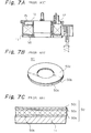
- Figs. 7A to 7C show an example of a conventional cable reel.
- Fig. 7A is a schematic longitudinal sectional view of a conventional cable reel.
- Fig. 7B is a perspective view of a conventional sound-absorbing material.
- Fig. 7C is a fragmentary cross sectional view of the sound-absorbing material shown in Fig. 7B.
- the conventional cable reel includes a movable member assembly 10 which rotates together with a steering wheel, and a stationary member assembly 11 which is secured to a stationary shaft on a body frame.
- the movable and stationary member assemblies 10 and 11 define an annular cable containing chamber 12 which accommodates a flat cable 15 in a coiled manner. Opposite ends of the flat cable 15 in the coiled manner are connected to lead wires which are led out from the movable and stationary member assemblies 10 and 11, respectively, to be connected to an external connector or electrical wires.
- the flat cable 15 is wound in the cable containing chamber 12 when the steering wheel is turned in either a clockwise or counter clockwise direction while the flat cable 15 is unwound in the chamber 12 when the steering wheel is turned in the other direction, so that a device (air bag) on the steering wheel is electrically connected to a power source on the body frame.
- the cable reel involves a problem in that an unpleasant sliding noise is generated when the lateral opposite edges of the flat cable 15 slide on upper and lower bearing surfaces of the cable containing chamber 12 upon winding and unwinding of the flat cable 15 in the chamber 12.
- the flat cable 15 caused to vibrate in an axial direction (from an upper to lower direction or from a lower to upper direction) of the steering wheel during idling or driving of the automotive vehicle, thereby giving rise to an unpleasant vibration noise due to collision between the bearing surfaces of the chamber 12 and the lateral opposite edges of the flat cable 15.
- Japanese Utility Model Publication No. HEI 6-36040 (1994) discloses a cable reel in which a highly lubricative sheet such as a polytetrafluoroethylene (PTFE) resin or the like is adhered to at least one of bearing surfaces of a cable containing chamber in order to attenuate sliding noise
- a highly lubricative sheet such as a polytetrafluoroethylene (PTFE) resin or the like is adhered to at least one of bearing surfaces of a cable containing chamber in order to attenuate sliding noise
- HEI 8-104471 discloses a cable reel in which a sound-absorbing material made of a resilient material such as a rubber or the like or a sound-absorbing material with the polytetrafluoroethylene (PTFE) resin is attached to bearing surfaces of stationary and movable member assemblies by means of clamps provided on the surfaces.
- a polytetrafluoroethylene resin sheet is adhered by way of PET (polyethylene telephthalate) to a surface of a rubber sheet since the former lacks adhesion to the latter.
- the polytetrafluoroethylene resin sheet disclosed in Japanese Utility Model Publication No. HEI 6-36040 (1994) can attenuate sliding noise on account of its high lubrication, it cannot reduce noise which is caused by collision of the flat cable onto the bearing surfaces of the cable reel due to axial vibrations of the cable in swirl. In particular, such unpleasant collision noise is likely to be accentuated when an engine is idling.
- the resilient sheet disclosed in Japanese Patent Public Disclosure No. HEI 8-104471 (1996) hardly attenuates sliding noise, since the lubrication between the flat cable and the resilient sheet is poor, although the sheet can reduce the collision or vibration noise.
- a rubber sheet 50a having a polytetrafluoroethylene (PTFE) resin sheet 50c provided thereon can attenuate and absorb both a sliding and vibration noise by means of a highly lubricative resin and rubber sheet.
- PTFE polytetrafluoroethylene
- the rubber sheet 50a cannot effectively absorb sliding noise and thus cannot obtain a substantial sound-absorbing effect since the sheet 50a is a flat plate having a single layer.
- a rubber sheet 50a, a polyethylene telephthalate (PET) film 50b and a polytetrafluoroethylene (PTFE) resin sheet 50c must be punched out into an annular shape adapted to be used, since the bearing surfaces of the cable containing chamber 12 is in an annular form. Consequently, this involves much loss of material. In particular, a total cost of the cable reel becomes high since the PTFE resin sheet is expensive.
- PET polyethylene telephthalate
- PTFE polytetrafluoroethylene
- the above sound-absorbing material involves a high cost due to an increase in working steps, since the PET film 50b is adhered to the rubber sheet 50a through an adhesive and then the PTFE resin sheet 50c is attached to the PET film 50b by way of an adhesive.
- the above sound-absorbing material gives rise to a problem in that it reduces a sound-absorbing effect since the hard PET film 50b is interposed between the rubber sheet 50a having a sound-absorbing function and the PTFE resin sheet 50c having a lubricative function. It is difficult to produce the PTFE resin sheet 50c having a low thickness since it is produced by means of skiving. Consequently, the sheet 50c on the market is usually more than 20 ⁇ m. Such a thick PTFE resin sheet 50c in addition to the hard PET film 50b will lower the sound-absorbing function.
- An object of the present invention is to provide a sound-absorbing material and a cable reel including the same which can effectively attenuate both a sliding and vibration noise and which can be produced inexpensively.
- a sound-absorbing material in accordance with the present invention comprises: two rubber sheets piled on each other, at least one of the two rubber sheets being provided on the inner surface with a ragged portion to define an air layer between the rubber sheets; and a highly lubricative layer formed directly on the outer surface of the one rubber sheet by coating the outer surface with a fluororesin system coating agent mixed with an adhesive.
- the air layer can be formed between the two rubber sheets since each opposing surface of at least one of the two rubber sheets is formed into a ragged surface. It is possible to attenuate noise with a high degree of efficiency by directing the noise onto the ragged surface of the rubber sheet. Thus, the sound-absorbing material of the present invention can absorb the noise with a high degree of efficiency.
- the polytetrafluoroethylene resin is formed into a sheet beforehand and the resin sheet is attached to the rubber sheet through the PET film, since it is difficult to directly adhere the resin sheet to the rubber sheet.
- a fluororesin system coating agent in a liquid form is mixed with the adhesive prior to being formed into a sheet, and the mixture in a liquid form is applied directly onto the surface of the rubber sheet by means of a spray, a brush, or a roller, and then the coated layer is heated to a given temperature and hardened to form a very thin and highly lubricative coating layer on the rubber sheet.
- the agent When the fluororesin system coating agent is used as it is and the agent mixed with the adhesive is applied onto the rubber sheet, the agent will fit on the rubber sheet and thus it is possible to directly form the highly lubricative coating layer made of the fluororesin system coating agent on the rubber sheet without using the PET.
- the application of the fluororesin system coating agent on the rubber sheet makes the thickness of the coating layer less than that of the conventional resin sheet, and as PET is not used, the sound-absorbing function of the rubber sheet can be enhanced and an adhesion step for a PET film and a PTFE resin sheet can be eliminated, thereby reducing work processes.
- a highly lubricative coating layer can be formed on a rubber sheet by first applying an adhesive on the rubber sheet and then applying a pure fluororesin system coating agent having no adhesive by means of a spray or the like.
- the fluororesin system coating agent may be a PTFE resin.
- a mixture of the fluororesin system coating agent of 95% in weight and the adhesive (prior to being hardened) of 5% in weight is preferable. If the fluororesin system coating agent is less than 95% in weight, lubrication of the agent becomes poor. If the adhesive is less than 5% in weight, adhesion becomes poor.
- the ragged portion on the entire inner surface of the one rubber sheet may include a number of tip-shaped or stripe-shaped protrusions to define an air layer between the two rubber sheets.
- the ragged portion in either the tip-shaped protrusions or stripe-shaped protrusions can absorb the noise efficiently.
- a sheet made of polyethylene telephthalate (PET) is attached to the outer surface of the other rubber sheet through an adhesive. This makes it easy to attach the rubber sheet to another member.
- a cable reel having any one of the above sound-absorbing materials comprises: a stationary member assembly; a movable member assembly mounted on the stationary member assembly; a cable containing chamber formed into an annular configuration by the stationary and movable member assemblies, the chamber being adapted to contain a flat cable in a coiled manner therein; and means for electrically leading opposite ends of the flat cable out from the stationary and movable member assemblies, respectively.
- the sound-absorbing material is attached to at least one of bearing surfaces of the cable containing chamber which face opposite lateral edges of the flat cable. The one bearing surface is adapted to bear a weight of the flat cable.
- the cable reel described above is attached to a steering device of an automotive vehicle to supply electrical power to an air bag system.
- the movable member assembly which rotates with a steering wheel is turned to one direction, the flat cable is wound in the cable containing chamber in the cable reel while the flat cable is unwound when the assembly is turned in the other direction.
- the lateral opposite edges of the flat cable in particular, the lateral lower edge which is subject to its own weight, slide on the bearing surfaces of the cable containing chamber, in particular, the lower bearing surface during rotary motion. Since the highly lubricative thin coating layer made of the PTFE resin or the like is formed on the rubber sheet mounted on the bearing surface of the cable containing chamber, it is possible to allow the flat cable to smoothly rotate on the bearing surface, thereby suppressing sliding noise.
- the sound-absorbing material having an annular configuration may be attached to the bearing surface of the cable containing chamber having an annular configuration.
- the sound-absorbing material including a plurality of sector pieces may be attached at an equidistance in a circumferential direction to the bearing surface of the cable containing chamber having an annular configuration.
- Each of the sector pieces is divergent from an inner peripheral edge of the bearing surface to an outer peripheral edge of the bearing surface.
- the sector pieces can be partially disposed on the bearing surface. Consequently, the contact area between the sound-absorbing material and the flat cable becomes small and thus can attenuate both sliding noise and vibration noise.
- a sound-absorbing material and a cable reel including the same in accordance with the present invention will be explained below by referring to Figs. 1 to 6.
- the sound-absorbing material is attached to a cable reel mounted on a steering device in an automotive vehicle.
- a main body of the cable reel of the present invention has the same structure as that of the conventional cable reel shown in Fig. 7A. In both structures, the same members are indicated by the same reference numbers.
- the cable reel of the present invention includes a movable member assembly 10 which is secured to a steering wheel (not shown) to be turned together with it, and a stationary member assembly 11 which is secured to a shaft (not shown) fixed on a body frame.
- the movable member assembly 10 has an upper wall 10a and an inner peripheral wall 10b while the stationary member assembly 11 has a lower wall 11a and an outer peripheral wall 11b.
- the movable and stationary member assemblies 10 and 11 define an annular cable containing chamber 12.
- the cable containing chamber 12 accommodates a flat cable 15 in a coiled manner. An inner end of the flat cable 15 in a coiled manner is connected to a lead wire 13 which is led out through an attaching hole 10c in the upper wall 10a of the movable member assembly 10.
- An outer end of the flat cable 15 in a coiled manner is connected to a lead wire 14 which is led out from the stationary member assembly 11.
- the flat cable 15 is wound in the cable containing chamber 12 when the steering wheel is turned in one direction while the flat cable 15 is unwound in the chamber 12 when the steering wheel is turned in the other direction.
- lead wires 13 and 14 are electrically coupled to each other through the flat cable 15, even if the steering wheel is turned to either direction.
- the flat cable 15 as shown in Fig. 2, includes a pair of insulation resin films 16a and 16b, and a conductive material 17 interposed between the films 16a and 16b.
- the flat cable 15 is wound and unwound in the cable containing chamber 12 while either one of lateral opposite edges 15a and 15b of the flat cable 15 is sliding on a lower annular flat bearing surface 12a of the cable containing chamber 12. Accordingly, a sound-absorbing material 20 is mounted on the lower bearing surface 12a, as shown in Fig. 3.
- the cable containing chamber 12 is provided on the upper wall with a plurality of elongate ribs 18 each of which extends radially and is spaced apart at a given distance in the circumferential direction. There is a slightly small clearance between the ribs 18 and the lateral upper edge 15a of the flat cable 15. Thus, no sliding noise is caused on the upper side in the cable containing chamber 12.
- the sound-absorbing material 20 may be mounted on the upper flat annular wall of the cable containing chamber 12 without providing the ribs 18 on the wall.
- the sound-absorbing material 20 in the first embodiment is formed into substantially the same annular configuration as the lower annular bearing surface 12a of the stationary member assembly 11.
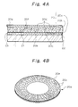
- the sound-absorbing material 20 has a dual layer structure comprising an upper rubber sheet 20b and a lower rubber sheet 20a, a front side surface 20e of the lower rubber sheet 20a and a back side surface 20f of the upper rubber sheet 20b are provided with a number of tip-shaped protrusions or ragged portions 20c and 20d, respectively.
- the front side surface 20e is opposed to the back side surface 20f through the protrusions 20c and 20d.
- the upper and lower rubber sheets 20b and 20a are integrated together by interconnecting the peripheral edges of the sheets to form the sound-absorbing material 20 having a thickness of about 1.3 mm.
- an air layer 21 is defined between the opposing surfaces 20e and 20f of the lower and upper rubber sheets 20a and 20b by means of the protrusions 20c and 20d. Consequently, sounds transmitted to the sound-absorbing material 20 are struck at the protrusions or the ragged portions 20c and 20d, are reflected on the protrusions irregularly, and are attenuated in the material 20. Thus, the sounds are effectively absorbed in the material 20.
- a highly lubricative coating layer 20g made of a fluororesin system material is formed on a surface of the sound-absorbing material 20, that is, a surface of the upper rubber sheet 20b.
- the highly lubricative coating layer 20g is formed on the entire front side surface of the upper rubber sheet 20b by mixing an adhesive in liquid form (for example, an acrylic system adhesive) in the polytetrafluoroethylene resin, spraying such a mixed liquid on the entire surface of the annular rubber sheet 20b to form a layer having a given thickness (for example 3 ⁇ m), heating at a given temperature, and hardening the layer.
- an adhesive in liquid form for example, an acrylic system adhesive
- the sound-absorbing material 20 constructed by the above manner is adhered to the lower bearing surface 12a of the stationary member assembly 11 through the PET film by means of the adhesive 23.
- the lateral lower edge 15b of the flat cable 15 slides on the highly lubricative coating layer 20g made of the polytetrafluoroethylene resin, sliding noise is attenuated.
- vibration noise is generated by the axial vibration of the flat cable 15 during the idling mode or the driving mode of the engine, when the flat cable 15 collides on the lower sound-absorbing material 20 in the empty weight direction.
- Such a vibration noise is struck on the protrusions 20c and 20d of the lower and upper rubber sheets 20a and 20b, thereby being absorbed in the sheets.
- the highly lubricative coating layer 20g is formed into an extremely thin layer (3 ⁇ m in this embodiment) by applying the fluororesin coating agent to the upper rubber sheet 20b, although the layer 20g itself is hard, the layer 20g does not interfere with the sound-absorbing function of the rubber sheet 21.
- vibration noise as well as sliding noise can be reduced by the sound-absorbing material 20.
- Fig. 5 shows a second embodiment of the cable reel having the sound-absorbing material 20 in accordance with the present invention.
- the second embodiment is the same as the first embodiment except that the sound-absorbing material 20 includes three sectoral pieces and each sectoral piece is disposed on the lower annular bearing surface 12a of the stationary member assembly 11 by an equal distance in a circumferential direction.
- Each sound-absorbing material 20 in the second embodiment has a dual layer structure including an upper rubber sheet 20b and a lower rubber sheet 20a in the same manner as that in the first embodiment.
- the upper and lower rubber sheets 20b and 20a are provided on opposing surfaces 20f and 20e with tip-shaped protrusions, respectively.
- An air layer 21 is defined between the upper and lower rubber sheets 20b and 20a.
- the sound-absorbing material 20 is divided into three sectoral pieces and the sectoral pieces are spaced apart from each other in a circumferential direction on the lower bearing surface 12a of the assembly 11, a total contact area between the sound-absorbing material 20 and the lateral edge of the flat cable 15 becomes small, thereby reducing sliding noise and vibration noise.
- the rubber sheet 25 may be provided on a surface 25a with stripe-shaped protrusions 25b.
- the tip-shaped projections 20c and 20d are formed on the opposing surfaces 20e and 20f of the rubber sheets 20a and 20b of the sound-absorbing material 20 in the first and second embodiments, the protrusions may be formed on either one of the sheets 20a and 20b in order to obtain a sound-absorbing effect.
- the cable reel of the present invention can be attached to not only the steering device but also a similar device.
- the sound-absorbing material of the present invention can be attached to not only the bearing surface or surfaces of the cable containing chamber but also a surface on which a member slides and collides in order to attenuate sliding noise and vibration noise.
- the sound-absorbing material can highly attenuate the sounds by defining an air layer between the two rubber sheets and bringing the sounds into collision onto the ragged portions in the air layer. This results in a high efficiency of sound-absorbing in comparison with a conventional sound-absorbing material having a single layer structure including a rubber sheet.
- the thickness of the highly lubricative coating layer very thin since it is formed by spraying uniformly a liquid mixture of an adhesive and a fluororesin system coating agent such as a PTFE directly onto the surface of the rubber sheet.
- the bearing surface which bears a lateral edge of the flat cable has a good lubrication, in the case where the sound-absorbing material is applied to the cable reel, thereby reducing sliding noise.
- vibration noise can be effectively absorbed and attenuated by the projections in the air layer defined between the two rubber sheets.
- the rubber sheet does not interfere with the sound-absorbing function since the highly lubricative coating layer on the rubber sheet is extremely thin in thickness.
- the sound-absorbing material of the present invention can effectively reduce both sliding noise and vibration noise.
- a quantity of the expensive polytetrafluoroethylene resin to be used can be reduced by 10% to 50% in comparison with the conventional polytetrafluoroethylene resin sheet formed into an annular shape piece by a punching or blanking manner, since the highly lubricative coating layer is very thin and the spraying requires a minimum quantity of the resin. Consequently it is possible to greatly lower a cost of the sound-absorbing material.
- the highly lubricative sound-absorbing material of the present invention can be formed merely by applying the fluororesin system coating agent to the surface of the rubber sheet. Thus, it is possible to further lower the cost.
Landscapes
- Engineering & Computer Science (AREA)
- Mechanical Engineering (AREA)
- Soundproofing, Sound Blocking, And Sound Damping (AREA)
- Steering Controls (AREA)
Applications Claiming Priority (3)
| Application Number | Priority Date | Filing Date | Title |
|---|---|---|---|
| JP9214961A JPH1167402A (ja) | 1997-08-08 | 1997-08-08 | 吸音材および該吸音材を備えたケーブルリール |
| JP21496197 | 1997-08-08 | ||
| JP214961/97 | 1997-08-08 |
Publications (2)
| Publication Number | Publication Date |
|---|---|
| EP0896402A2 true EP0896402A2 (de) | 1999-02-10 |
| EP0896402A3 EP0896402A3 (de) | 1999-11-03 |
Family
ID=16664442
Family Applications (1)
| Application Number | Title | Priority Date | Filing Date |
|---|---|---|---|
| EP98306171A Withdrawn EP0896402A3 (de) | 1997-08-08 | 1998-08-03 | Schalldämmendes Material und Anwendung in Kabeltrommeln |
Country Status (3)
| Country | Link |
|---|---|
| US (1) | US5975453A (de) |
| EP (1) | EP0896402A3 (de) |
| JP (1) | JPH1167402A (de) |
Families Citing this family (7)
| Publication number | Priority date | Publication date | Assignee | Title |
|---|---|---|---|---|
| JP2000350346A (ja) * | 1999-05-31 | 2000-12-15 | Sumitomo Wiring Syst Ltd | ケーブルリールの吸音構造 |
| DE19948724A1 (de) * | 1999-10-09 | 2001-04-12 | Eaton Corp Eaton Ct Cleveland | Verfahren zur Herstellung eines Gehäuses für eine elektrische Verbindungseinrichtung zwischen gegeneinander drehbaren Teilen |
| US6299454B1 (en) * | 2000-03-23 | 2001-10-09 | Methode Electronics, Inc. | Steering column interconnector having conductive elastic rolling contacts |
| US20050284689A1 (en) * | 2004-06-23 | 2005-12-29 | Michael Simpson | Clockspring with sound dampener |
| JP4665848B2 (ja) * | 2006-03-15 | 2011-04-06 | 日立電線株式会社 | コネクタ構造 |
| JP6160125B2 (ja) * | 2013-03-01 | 2017-07-12 | 株式会社ジェイテクト | 転がり軸受装置 |
| CN117068880A (zh) * | 2022-05-16 | 2023-11-17 | 达碧珂机场解决方案德国有限责任公司 | 用于飞机服务地坑的电力供应系统 |
Citations (5)
| Publication number | Priority date | Publication date | Assignee | Title |
|---|---|---|---|---|
| US4469736A (en) * | 1982-05-22 | 1984-09-04 | Metzeler Schaum Gmbh | Planar element for the absorption of air-transmitted sound and method of manufacturing the same |
| EP0417350A1 (de) * | 1989-09-12 | 1991-03-20 | Petri AG | Stromleitungsverbinder zur Überbrückung von Leiterunterbrechungen zwischen gegeneinander drehbaren Teilen |
| JPH0636040Y2 (ja) * | 1988-03-31 | 1994-09-21 | アルプス電気株式会社 | ケーブルリール |
| JPH08104471A (ja) * | 1994-10-04 | 1996-04-23 | Matsushita Electric Ind Co Ltd | ケーブルリール |
| EP0848460A1 (de) * | 1996-12-13 | 1998-06-17 | Sumitomo Wiring Systems, Ltd. | Stark schmierendes und Geräusche schluckendes Material mit entsprechender Anwendung für eine Vorrichtung zum Aufrollen von Kabeln |
Family Cites Families (7)
| Publication number | Priority date | Publication date | Assignee | Title |
|---|---|---|---|---|
| US5296287A (en) * | 1992-11-25 | 1994-03-22 | Textiles Coated Incorporated | Single membrane insulation material |
| JP3435556B2 (ja) * | 1994-05-25 | 2003-08-11 | インターメタリックス株式会社 | 固体潤滑皮膜形成方法 |
| US5798181A (en) * | 1994-10-04 | 1998-08-25 | W. L. Gore & Associates, Inc. | Fluoropolymer coated elastomeric rollers and structures |
| JPH08162242A (ja) * | 1994-12-09 | 1996-06-21 | Yazaki Corp | 固定体と回転体との電気的接続装置 |
| JPH08190000A (ja) * | 1995-01-05 | 1996-07-23 | Fuji Photo Film Co Ltd | 放射線像変換パネル |
| JPH08306458A (ja) * | 1995-05-02 | 1996-11-22 | Yazaki Corp | 回転体と固定体との間の電気的接続装置 |
| JP3087623B2 (ja) * | 1995-09-04 | 2000-09-11 | 住友電装株式会社 | ワイヤハーネス結束用テープ及びワイヤハーネス |
-
1997
- 1997-08-08 JP JP9214961A patent/JPH1167402A/ja not_active Withdrawn
-
1998
- 1998-07-31 US US09/127,178 patent/US5975453A/en not_active Expired - Fee Related
- 1998-08-03 EP EP98306171A patent/EP0896402A3/de not_active Withdrawn
Patent Citations (5)
| Publication number | Priority date | Publication date | Assignee | Title |
|---|---|---|---|---|
| US4469736A (en) * | 1982-05-22 | 1984-09-04 | Metzeler Schaum Gmbh | Planar element for the absorption of air-transmitted sound and method of manufacturing the same |
| JPH0636040Y2 (ja) * | 1988-03-31 | 1994-09-21 | アルプス電気株式会社 | ケーブルリール |
| EP0417350A1 (de) * | 1989-09-12 | 1991-03-20 | Petri AG | Stromleitungsverbinder zur Überbrückung von Leiterunterbrechungen zwischen gegeneinander drehbaren Teilen |
| JPH08104471A (ja) * | 1994-10-04 | 1996-04-23 | Matsushita Electric Ind Co Ltd | ケーブルリール |
| EP0848460A1 (de) * | 1996-12-13 | 1998-06-17 | Sumitomo Wiring Systems, Ltd. | Stark schmierendes und Geräusche schluckendes Material mit entsprechender Anwendung für eine Vorrichtung zum Aufrollen von Kabeln |
Also Published As
| Publication number | Publication date |
|---|---|
| JPH1167402A (ja) | 1999-03-09 |
| US5975453A (en) | 1999-11-02 |
| EP0896402A3 (de) | 1999-11-03 |
Similar Documents
| Publication | Publication Date | Title |
|---|---|---|
| EP0848460A1 (de) | Stark schmierendes und Geräusche schluckendes Material mit entsprechender Anwendung für eine Vorrichtung zum Aufrollen von Kabeln | |
| TW200300396A (en) | Speaker for vehicle and installation structure therefor | |
| EP0895900B1 (de) | Kabeltrommel mit geräuschabsorbierendem Material und Verfahren zur Herstellung des geräuschabsorbierenden Materials für die Kabeltrommel | |
| US5975453A (en) | Sound-absorbing material and a cable reel including the same | |
| US6196488B1 (en) | Sound-absorbing material and a cable reel including the same | |
| US6152394A (en) | Sound-absorbing material and a cable reel including the same | |
| CA2095975A1 (en) | Motor brush spring subassembly | |
| EP1058357A1 (de) | Schallabsorbierende Anordnung für Kabeltrommel | |
| JP2000327230A (ja) | ケーブルリールの吸音構造 | |
| EP1013508A3 (de) | Tülle mit elastischer Flansch zur Befestigung auf einer Tafel | |
| JP2000327271A (ja) | ケーブルリールの吸音構造 | |
| JPH10200283A (ja) | 電子回路のシールドケース | |
| JP3821447B2 (ja) | 索式ミラー制御装置 | |
| JPH10154564A (ja) | 高滑性吸音材および該高滑性吸音材を備えたケーブルリール | |
| JP3087623B2 (ja) | ワイヤハーネス結束用テープ及びワイヤハーネス | |
| JPH10140733A (ja) | 構造物の外装材及び外装材に対する内装材の固定方法 | |
| JP2667808B2 (ja) | 防音カバーを備えたモータ | |
| JPH10154563A (ja) | 高滑性吸音材および該高滑性吸音材を備えたケーブルリール | |
| JP2506943Y2 (ja) | ア―ス具付除電ブラシ | |
| JP3384942B2 (ja) | 回転コネクター | |
| JPH08301535A (ja) | 連続する圧着端子などの巻取り具 | |
| JP3374105B2 (ja) | 回転コネクタ | |
| JP2604030Y2 (ja) | ドアトリム上端部表皮材処理構造 | |
| JPH11265773A (ja) | 回転コネクタ装置 | |
| JPH08284784A (ja) | スタータ |
Legal Events
| Date | Code | Title | Description |
|---|---|---|---|
| PUAI | Public reference made under article 153(3) epc to a published international application that has entered the european phase |
Free format text: ORIGINAL CODE: 0009012 |
|
| 17P | Request for examination filed |
Effective date: 19980819 |
|
| AK | Designated contracting states |
Kind code of ref document: A2 Designated state(s): DE FR GB |
|
| AX | Request for extension of the european patent |
Free format text: AL;LT;LV;MK;RO;SI |
|
| PUAL | Search report despatched |
Free format text: ORIGINAL CODE: 0009013 |
|
| AK | Designated contracting states |
Kind code of ref document: A3 Designated state(s): AT BE CH CY DE DK ES FI FR GB GR IE IT LI LU MC NL PT SE |
|
| AX | Request for extension of the european patent |
Free format text: AL;LT;LV;MK;RO;SI |
|
| RIC1 | Information provided on ipc code assigned before grant |
Free format text: 6H 01R 35/04 A, 6H 01R 35/02 B |
|
| AKX | Designation fees paid |
Free format text: DE FR GB |
|
| 17Q | First examination report despatched |
Effective date: 20020930 |
|
| GRAH | Despatch of communication of intention to grant a patent |
Free format text: ORIGINAL CODE: EPIDOS IGRA |
|
| RIC1 | Information provided on ipc code assigned before grant |
Free format text: 7H 01R 35/04 A, 7H 01R 35/02 B, 7B 60R 13/08 B, 7B 60R 16/02 B, 7G 10K 11/16 B, 7E 04B 1/82 B |
|
| RIN1 | Information on inventor provided before grant (corrected) |
Inventor name: MAEGAWA, AKIHITO,SUMITOMO WIRING SYSTEMS LTD, Inventor name: IIZUKA, TETSUYA,SUMITOMO WIRING SYSTEMS, LTD Inventor name: SAKATA, TOMOYUKI,HARNESS SYS. TECHN. RES. LTD. |
|
| STAA | Information on the status of an ep patent application or granted ep patent |
Free format text: STATUS: THE APPLICATION IS DEEMED TO BE WITHDRAWN |
|
| 18D | Application deemed to be withdrawn |
Effective date: 20030603 |