EP0894637B1 - Drucker mit mehreren Druckköpfen für grossen Druckbereich - Google Patents
Drucker mit mehreren Druckköpfen für grossen Druckbereich Download PDFInfo
- Publication number
- EP0894637B1 EP0894637B1 EP98305954A EP98305954A EP0894637B1 EP 0894637 B1 EP0894637 B1 EP 0894637B1 EP 98305954 A EP98305954 A EP 98305954A EP 98305954 A EP98305954 A EP 98305954A EP 0894637 B1 EP0894637 B1 EP 0894637B1
- Authority
- EP
- European Patent Office
- Prior art keywords
- head
- printer
- width
- mode
- Prior art date
- Legal status (The legal status is an assumption and is not a legal conclusion. Google has not performed a legal analysis and makes no representation as to the accuracy of the status listed.)
- Expired - Lifetime
Links
Images


Classifications
-
- B—PERFORMING OPERATIONS; TRANSPORTING
- B41—PRINTING; LINING MACHINES; TYPEWRITERS; STAMPS
- B41J—TYPEWRITERS; SELECTIVE PRINTING MECHANISMS, i.e. MECHANISMS PRINTING OTHERWISE THAN FROM A FORME; CORRECTION OF TYPOGRAPHICAL ERRORS
- B41J3/00—Typewriters or selective printing or marking mechanisms characterised by the purpose for which they are constructed
- B41J3/54—Typewriters or selective printing or marking mechanisms characterised by the purpose for which they are constructed with two or more sets of type or printing elements
Definitions
- the present invention relates to ink jet or bubble jet printers which have multiple printing heads, and particularly relates to the provision of plural print modes for such printers, including the provision of a wide width print mode and a standard width print mode.
- ink jet printers are provided with multiple ink jet print heads, such as two or three print heads.
- the multiple print heads though mounted on a common carriage, are each capable of independent operation, thereby providing the ability to decrease overall printing time (by overlapped printing by each print head), or to increase overall ink capacity (by providing differently-colored inks in the ink reservoirs for each print head).
- Figure 1 illustrates diagrammatically a conventional ink jet printer having multiple print heads.
- an ink jet printer 10 having two print heads, namely print head A and print head B.
- the print heads are mounted for lateral reciprocal movement across a support surface for a recording medium, from the position indicated by solid lines to the position indicated by dotted lines.
- Print head A can print in area 11
- print head B can print in area 12
- both print head A and print head B can print in fully overlapped relation in area 13.
- These areas all correspond in lateral width to standard A-4 size width or standard 81 ⁇ 2 x 11 inch width.
- a recording material loaded against paper base position 14, when advanced by printer 10 by unshown feeding means can be printed upon by print head A, by print head B, or by print heads A and B in a fully overlapped mode.
- United States Patent No. 4,204,779 describes an impact printer having a pair of daisywheel print heads mechanically linked at a fixed lateral separation of 55 columns.
- the purpose of the arrangement is to provide a character set twice as extensive as that provided by a single daisywheel.
- Software control permits two modes of operation. In the so-called concurrent mode, a line buffer is used and characters 55 columns apart are printed in parallel during one continuous movement of the pair of print heads. In a slower, sequential mode, adjacent characters are printed one after the other, the appropriate one of the two print heads being moved to the current print position, if necessary, prior to the printing of each character.
- Scan area 16 is both larger than the printable area for standard width recording media (i.e., areas 11, 12 and 13).
- the additional scan width for head B, namely 16a, is not printed on and is essentially wasted.
- the invention provides a multi-head printer comprising:
- the invention provides a printing method for a multi-head printer having at least first and second print heads mounted for lateral reciprocal movement across a support surface for a recording medium, the first and second print heads being laterally displaced with respect to each other such that a first lateral print area is printable by both of the first and second print heads and such that a portion of a second and larger lateral print area is printable by the second print head but not by the first print head, the printing method comprising the steps of:
- the invention provides a print driver which when executed in a host computer causes all the steps of the method described above to be performed; and a computer-readable medium on which is stored code which when executed in a host computer causes all the steps of the method described above to be performed.
- the invention provides a printing system comprising:
- An embodiment of the invention provides an additional print mode for printing on wide width recording media (such as A-3 or 11 x 17 inch ledger paper) but with only one print head which, in the example described above, would be print head B. More particularly, in addition to a standard width print mode in which fully or partially overlapped printing by both print heads is performed in a standard width area, the embodiment provides a wide-width print mode in which printing is performed by only one print head and not the other but over a wider width.
- wide width recording media such as A-3 or 11 x 17 inch ledger paper
- this embodiment can provide a wide-width printing capability for printers which heretofore have been limited to a standard width, and can provide the wide width printing capability without significantly increasing the overall footprint of the printer. Specifically, since multi-head printers are already sized to accommodate the additional scan width of one of the print heads, there is no need to increase the overall size of the printer to additionally accommodate wider format recording media. Thus, the overall footprint of the printer remains substantially the same even though wider format recording media can now be accommodated.
- one conventional multi-head printer provides black ink only for print head B, and cyan, magenta and yellow inks for print head A.
- An embodiment of the invention would preserve four color printing in standard widths; whereas for wider format print media, which typically would be accounting ledger sheets for which four color printing is not normally needed, the embodiment would provide black only print capabilities which were not heretofore obtainable.
- sensing means may be provided so as to sense head configuration such as what type of print heads are mounted (for example, black only or three- or four-color print heads), and detection means can be provided so as to detect the width of the recording medium present in the paper path.
- a controller in the printer automatically selects the most appropriate print mode based on the sensed print head configuration. If desired, it is possible to select mode also based on the detected print media width.
- the sensed print head configuration and/or the detected print media width can be transmitted over a bi-directional interface back to a host computer from which print data is sent, and the host computer can (1) automatically select the most appropriate print mode based on the data received over the bi-directional interface, or (2) automatically select the most appropriate print mode based on print data characteristics such as color content or page width, or (3) allow a user to select the most appropriate print mode, or (4) permit a combination of any of the foregoing, all based on the available print modes.
- Embodiments of the invention include a printer driver executable in a host computer so as to output print data to a multi-head printer having a standard width print mode for overlapped printing by two print heads and a wide-width print mode for printing by only one print head and not the others. Based on print head configuration and/or print data characteristics, the print driver determines what print modes are available. The print driver then either automatically selects the most appropriate print mode, or allows a user to select the print mode, whereupon print data is sent to the printer together with the selected print mode so as to effect printout of the print data in the selected mode.
- a purge unit 35 is provided to purge the nozzles of print heads A and B so as to ensure free flow of ink therethrough.
- the purge unit is outside of the paper feed path, as defined by fixed paper base registration position 39, against which recording media of all sizes are registered in preparation for printing.
- the printer includes an automatic sheet feeder 36 to feed sheets of standard width from supply tray 29a.
- a manual feed slot 38 is provided in the rear of printer 30 to accept wide width recording medium, which are too large to be fed from supply tray 29a by the auto sheet feeder.
- Sensing means such as keyed mechanical interlocks, are provided for each of heads A and B so as to sense the type of head mounted on the carriage, thereby to detect head configuration.
- Detection means 37 such as LED detection arrays, are provided in a paper feed path of printer 30 so as to detect the width of the recording medium fed therethrough.
- the lateral scanning width of head A is depicted at 40, and the lateral scanning width of head B is depicted at 41.
- head A printable area is depicted at 42
- head B printable area is depicted at 44.
- 45 depicts an area in which both of head A and head B can print in fully or partially overlapped relation with both of head A and head B being able to print throughout the entire representative computer equipment according to one embodiment of the invention.
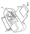
- Figure 3 is a close-up perspective view of a printer according to one embodiment of the invention.
- Figure 4 is a diagram for explaining head configuration of a multi-head printer according to one embodiment of the invention.
- Figure 5 is a view showing print element (or nozzle) arrangement in a print head.
- Figure 6 is a detailed block diagram showing the internal construction of the computing equipment and the printer shown in Figure 2.
- Figure 7 is a flow diagram for explaining print mode selection in the printer.
- Figure 8 is a flow diagram for explaining a print driver and print mode selection therein.
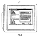
- Figure 9 is a representative example of a prompt for user selection of printing mode.
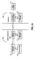
- Figure 10 is a high-level functional block diagram of the interaction between the host computer and the printer.
- Figure 11 is a view for explaining head combinations usable for printing in a printer according to one embodiment of the invention.
- Figure 12 is a view for explaining how printer footprint is affected by relative placement of the fixed paper registration position and the print head purge/maintenance station.
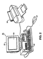
- FIG. 2 is a view showing the outward appearance of a representative printer 30 according to one embodiment of the invention, connected to representative computing equipment which incorporates a print driver according to other aspects of the invention.
- computing equipment 20 such as an IBM PC or PC-compatible computer having a windowing operating system such as a Microsoft Windows® operating system.
- Computing equipment 20 is provided with a display monitor 23 having a display screen 22 on which computing equipment 20 displays images to the user.
- Computing equipment 20 is further provided with a floppy disk drive 24 with which removable floppy disk media may be read or written, fixed disk drive 25 for storing data files and application program files, a keyboard 26 for permitting input of text data and manipulation of objects displayed on display screen 22, and a pointing device 27 such as a mouse or the like which is also provided to permit manipulation of objects on display screen 22.
- a floppy disk drive 24 with which removable floppy disk media may be read or written
- fixed disk drive 25 for storing data files and application program files
- keyboard 26 for permitting input of text data and manipulation of objects displayed on display screen 22
- a pointing device 27 such as a mouse or the like which is also provided to permit manipulation of objects on display screen 22.
- connections may be provided to computing equipment 20, such as a connection or interface to a local area network or to facsimile/modem/telephone interface, both for sending and receiving color image data as well as other files such as files which include program instruction sequences by which computing equipment 20 is operating.
- Printer 30 is a color ink jet printer that includes multiple print heads (here, two print heads) and is interfaced to computing equipment 20. Interface between computing equipment 20 and printer 30 may be of any variety, such as an infrared interface or a standard printer interface, but the interface shown here is an IEEE 1284 bi-directional or Centronix interface. Printer 30 includes a pair of ink jet print heads, with each having plural ink ejection nozzles aligned vertically in groups of each of plural colors, as described more fully below.
- stored application programs such as graphics application programs, drawing application programs, desktop publishing application programs, and the like, are selectively activated to process and to manipulate data. Also in accordance with operator instructions, and based on those stored application programs, commands are issued to display images on monitor 23 and also to print images appearing on monitor 23 on printer 30.
- Figure 3 is a close-up perspective view of printer 30, showing first and second print heads A and B mounted for lateral reciprocal movement in the direction of arrow l across an unshown support surface for a recording medium.
- Each print head carries an ink reservoir to supply ink ejected by print nozzles thereon.
- each print head carries two ink jet reservoirs: a black ink reservoir, and a combined cyan, magenta and yellow (CMY) ink reservoir.
- the two ink reservoirs are respectively depicted at 28a and 28b, for print head B.
- the print heads need not be identically configured; rather, as described below, the print heads can be configured differently such as black ink only for print head B and CMY ink only for print head A.
- Unshown sensing means such as a mechanical key sensor senses the type of print head and ink reservoir color mounted at each position of A and B.
- the ink reservoirs need not necessarily be carried on their respective print heads; rather, ink can be supplied through flexible tubing from off-head mounted remote ink reservoirs.
- a standard-width recording medium such as paper is fed from supply tray 29a, through a feed path past heads A and B for printing thereon, and ejected onto eject tray 29b.
- Wide-width recording media may be fed from supply tray 29a, but more preferably wide-width media is fed from a manual feed port (depicted in Figure 4) in the rear of printer 30.
- Detection means such as a light sensor array, detects paper width so as to determine whether the recording medium is, for example, A-4, 81 ⁇ 2 x 11, A-3 or 11 x 17 ledger.
- FIG. 4 is a schematic view of the arrangement of the dual print heads in printer 30.
- Each of print heads A and B, each carrying its respective ink reservoir(s), is mounted on carriage 33 for reciprocal back and forth lateral motion on guide rail 34.
- the carriage 33 is driven across guide rail 34 by suitable driving means, such as a belt or the like, so as to drive print heads A and B in scanning motions across a support surface for the recording medium.
- a fixed separation on carriage 33 is provided between print heads A and B.
- area 45 corresponds to a width of A-4 recording medium, (that is, 210 mm)
- area 46 corresponds to a width of A-3 recording medium (that is, 297 mm).
- Figure 5 shows the arrangement of print elements on each of print heads A and B.
- the print elements are vertically oriented and arranged in groups for each ink color, with 24 nozzles being provided for yellow ink, 24 nozzles being provided for magenta ink, 24 nozzles being provided for cyan ink, and 64 nozzles being provided for black ink.
- the print elements are arranged vertically, or near-vertically with a slight slant angle that corresponds to formation of a vertical line during rapid sequential firing of the nozzles during movement of the print head in the direction of arrow A.
- the print head is driven horizontally across the recording medium so as to effect printing in bands, with one band corresponding to the 24 rows of pixels printed during one scan of the print head.
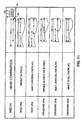
- Figure 11 depicts the head combination usable for printing.
- the upper right corner of Figure 11 schematically depicts the arrangement of printer 30, and shows the relative position of print heads A and B, carriage 33, purge unit 35, and fixed paper registration position 39.
- single head printouts by head B only
- partially overlapped multi-head printouts are available.
- single head printouts using either head A or head B
- partially- or fully-overlapped multi-head printouts are available.
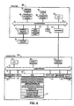
- FIG. 6 is a detailed block diagram showing the internal construction of computing equipment 20 and the internal construction of printer 30.
- computing equipment 20 includes a central processing unit (CPU) 50 such as a programmable microprocessor interfaced to computer bus 51.
- CPU central processing unit
- display interface 52 for interfacing to display 23
- printer interface 53 for interfacing to printer 30
- floppy disk drive interface 54 for interfacing to floppy disk 24
- keyboard interface 55 for interfacing to keyboard 26, and a pointing device 56 interface for interfacing to pointing device 27.
- Main memory 57 such as random access memory (RAM) interfaces to computer bus 51 so as to provide CPU 50 with access to memory storage.
- RAM random access memory
- CPU 50 loads those application instruction sequences from disk 25 (or other storage media such as media accessed via a network or a floppy disk drive 24) into main memory 57 and executes those stored program instruction sequences out of the main memory.
- Read only memory (ROM) 58 is provided for storing invariant instruction sequences, such as start-up instruction sequences or basic input/output operating system (BIOS) sequences for operation of keyboard 26.
- invariant instruction sequences such as start-up instruction sequences or basic input/output operating system (BIOS) sequences for operation of keyboard 26.
- BIOS basic input/output operating system
- fixed disk 25 stores program instruction sequences for the windowing operating system and for various application programs such as graphics application programs, drawing application programs, desktop publishing application programs, and the like.
- fixed disk 25 also stores color image files such as might be displayed on monitor 23 or printed on printer 30 under control of a designated application program.
- Fixed disk 25 also stores a color monitor driver which controls how RGB color primary values are provided to display interface 52, and a print driver 59 which is a print driver for controlling how CMYK color component values are derived from RGB color primary values and provided to printer interface 53 together with a print mode selected in accordance with the invention, for print out by printer 30.
- Other device drivers are also stored on fixed disk 25, for providing appropriate signals to various devices, such as network devices, facsimile devices, and the like, connected in computing equipment 20.
- printer 30 includes a CPU 60, such as a V853 single chip microprocessor, connected to computer bus 61. Also connected to computer bus 61 are RAM 62, ROM 63, external memory interface 64, interface 65 to a print engine, interface 66 to a panel, and interface 67 to computer 20.
- RAM 62 is comprised of working storage for printer 30, and in particular includes a print data buffer area as described more fully below.
- ROM 63 is comprised by a font ROM for storing font data, a program ROM to store program instruction sequences used to control printer 30, and invariant data such as printer model number and the like.
- External memory interface 64 interfaces to external memory cartridges such as cartridge 70 that provide additional fonts for printer 30, or provide additional random access memory.
- Interface 65 interfaces to a print engine 71 including interfaces to printer heads A and B, an interface to the drive means for carriage 33, an interface to purge unit 35, and other unshown interfaces such as interfaces to document feed sections and interfaces to printer nozzle controls.
- Interface 66 to a panel includes an interface to panel 72, comprised, for example, by an LCD display for displaying status of the printer, LEDs for indicating on-line and off-line or error conditions, and various control buttons for setting and otherwise interfacing with printer 30.
- Interface 67 includes a complementary interface to printer interface 53 of computer 20.
- CPU 60, bus 61, RAM 62 and ROM 63 comprise control means for controlling operation of printer 30.
- Figure 6 illustrates the individual components of printer 30 as separate and distinct from one another, it is preferable that at least some of those components are combined.
- external memory interface 64, interface 65 to the print engine, interface 66 to the panel, and interface 67 all into a single gate array.
- the aforementioned gate array is further combined with CPU 60, RAM 62 and ROM 63 into a so-called four-in-one chip, which eliminates the need to provide leads to a separate computer bus and lessens the number of interconnections needed so as to fabricate a control portion for printer 30.
- FIG 10 is a high-level functional block diagram illustrating how computer 20 interacts with printer 30 in the practice of the invention.
- application program 75 such as an image processing application stored on disk 25
- the windowing operating system 76 issues graphics device interface calls to printer driver 59.
- printer driver 59 selects a print mode and derives print data corresponding to the print instruction from application 75, and stores the print data in print data buffer 77. Thereafter, and again in accordance with the invention, print driver 59 obtains print data from print data buffer 77 and transmits the print data to printer 30 for printout thereby.
- printer 30 through use of control software 81 comprised by the program stored in ROM 63 receives the print data from print driver 59 and stores it in a print data buffer 82.
- Print data buffer 82 resides in RAM 62.
- control software 81 retrieves the stored print data from print data buffer 82, processes it such as by decompression, and transmits it to print engine 71 for printout thereby.
- Figure 7 is a flow diagram showing process steps by which the control means of printer 30 selects a print mode for operation in accordance with the invention.
- the process steps shown in Figure 7 are stored as code on a computer-readable medium such as ROM 63 for execution by CPU 60 in printer 30.
- print mode selection might also be based on a detected width of the recording medium or on whether or not a preference has been set as to print quality.
- print quality it should be borne in mind that print quality will generally be higher when printing is performed with only a single head, since printing with a single head will ensure that print quality is not adversely affected by possible misalignments or other mismatches such as a density mismatch between each of multiple print heads.
- print output performed by print head A will likewise be misaligned with respect to print output formed by print head B.
- Corresponding Application No. entitled “Auto-alignment System for a Printing Device”, filed by the inventors herein, describes how to detect and compensate for such a misalignment, but in general it is difficult to compensate for misalignment better than ⁇ 1 ⁇ 2 a print element. Such a misalignment will appear as a vertical step in the printed output, and will be avoided altogether if printing is confined to printing by only a single print head.
- step S701 obtains head configuration through readout of a sensing means.
- step S701 reads a sensing means so as to determine what type of print head is mounted at each of print positions A and B.
- each of the print positions may have mounted therein an all-black print cartridge, a three-color (CMY) print cartridge, a four-color (CMYK) print cartridge, or a photo print cartridge.
- CMY three-color
- CMYK four-color
- a photo print cartridge refers to a print cartridge having inks of lesser density than normal, so as to provide additional inks to select from and to produce more photo-realistic printed output.
- no print cartridge at all is mounted at a particular print station, or the print cartridge mounted at a particular print station is not functioning properly such as through an out-of-ink condition or other malfunction.
- step S702 determines the available print modes based on the printer head configuration.
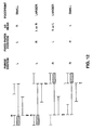
- available print modes refers to the print modes that are possible based on the print head configuration and based on the head combinations shown in Figure 11. For example, if printer head A is a three-color print head and printer head B is a black-only print head, then available print modes include standard width single- or multi-head black-and-white printout, standard width multi-head color printout, and wide width single head black-and-white printout; whereas if head A is replaced with a four-color print head then the available print modes in addition include a wide width multi-head black-and-white printout. Available print modes based on some typical head configurations for each of heads B and A are shown in the following Table 1.
- step S703 Flow advances to steps S703 through S706 in which one print mode from the available print modes is automatically selected by the control means. Selection may be based on detected width of the recording medium, or it may be based on whether or not a preference has been set as to print quality, or both. If selection based on detected medium width is desired, then step S703 detects the width of the recording medium by reference to detection means 37. Flow then advances to step S704 which determines whether a print quality preference has been set by the user. Typically, a print quality preference may be set by a manually-operable switch on the face of printer 30, or may be set by interaction of the user with the control panel of the printer. Print quality preference can include a choice from among "HIGH”, “FAST”, or "AUTO SELECT". Based on whether a print quality preference has been set, flow advances either to step S705 or to step S706.
- step S705 selects a print mode from the available print modes based on the print quality preference.
- step S706 in which the fastest print mode is selected based on the print modes available for the detected width of the recording medium. In either event, flow then advances to step S707 in which printer 30 prints in the selected print mode.
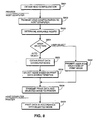
- FIG. 8 is a flow diagram showing process steps for a printer driver in accordance with the invention.
- Process steps S803 through S808 are stored as code on a computer-readable medium for execution by CPU 50 in host computer 20, such as being stored in disk 25.
- the process step shown in Figure 8 are a printer driver executable in a host computer so as to set a printer mode for printout of a print image by an ink jet printer having multiple print heads laterally spaced apart with respect to each other.
- the printer includes plural print modes including at least a standard width print mode for overlapped printout in a first lateral print area by both of first and second print heads, as well as a wide width print mode for printout in a second and larger lateral print area by only one print head and not any others.
- the process steps determine available print modes based on printer head configuration, and automatically select a print mode from the available print modes based on print data characteristics such as color content and desired print width. Alternatively, the available print modes may be displayed for user selection of one of the available print modes. Print data and the selected mode are thereafter transmitted to the printer for printout thereby.
- step S801 the printer 30 obtains print head configuration in a manner similar to that in step S701, and in step S802 printer 30 transmits the head configuration over the bi-directional interface to host computer 20.
- step S803 host computer 20 determines the available print modes. Processing for step S803 is identical to that of step S702, with the exception that processing is performed in host computer 20 rather than in printer 30.
- step S804 host computer 20 determines whether to prompt a user to select a print mode from the available print modes, or whether to automatically select a print mode based on print data characteristics. If automatic selection is desired, then flow advances to step S805 in which host computer 20 examines the characteristics of the print data. Specifically, characteristics of the print data includes color content of the print data, as well as desired width of printout of the print data. The phrase "color content" refers, for example, to whether the print data is black-and-white print data, full-color print data, or photo-quality print data. Based on the print data characteristics, step S806 selects one of the available print modes for use by the printer. Flow then advances to step S808 in which host computer 20 transmits the print data and the selected mode to printer 30, whereupon printer 30 prints the data in accordance with the selected mode (step S809).
- step S804 user selection is desired, then flow branches to step S807 in which the user is prompted to select a print mode from the available print modes.
- Figure 9 shows a suitable graphical user interface by which a user is prompted to select a display mode from the available display modes. As seen in Figure 9, all available print modes are displayed for selection by the user, and in addition, the user is presented with a variety of options as to print width, quality, and color. If "AUTO SELECT" is selected for each of these options, then the user is presented with the widest variety of available print modes. On the other hand, by selecting a specific width, quality or color content, the user may narrow his choices of available print modes, thereby to assist him in selecting the most appropriate print mode for desired print output. When the user is satisfied with his choice, the "PRINT" button is selected, thereby verifying his selection to host computer 20.
- printer footprint is affected by head separation between heads A and B.
- Figure 12 depicts how printer footprint is additionally affected by the relative placement of fixed paper registration guide 39 and print head purge station 35. That is, Figure 12 depicts four possible combinations of positions for registration guide 39 and purge station 35: left/left, left/right, right/left and right/right. For each combination, the home position of carriage 33 and heads A and B is depicted in solid lines, whereas the far scanned position of the carriage and heads is depicted in dotted lines.
- Frar scanned position means the position to which the carriage and heads must travel so as to ensure that fully overlapped printing is possible for standard width recording media.
- the lowermost combination i.e., right/right
- the wide mode (A3) head is the left head on carriage 33, and the far-scanned position is shown in dotted lines.
- the overall effect is a printer with a small footprint.
- the wide mode head is the right head, and the far-scanned position is depicted in dotted lines. Again, the overall footprint is small.
- the wide mode print head may be either the left head or the right head
- the far-scanned position is depicted in dotted lines.
- the overall footprint is larger.
- a similar larger footprint is obtained for the right/left combination. It can therefore be observed that the overall printer footprint is small if the purge station 35 and the fixed paper registration guide 39 are positioned on the same side of the printer, with the purge station located outside of the paper feed path.
- the wide mode print head it is further preferable for the wide mode print head to be opposite to the fixed paper position.
- the present invention can be implemented as computer code stored on a medium or in electronic form e.g. a downloaded or stored printer driver.
Landscapes
- Printers Characterized By Their Purpose (AREA)
- Ink Jet (AREA)
- Record Information Processing For Printing (AREA)
- Accessory Devices And Overall Control Thereof (AREA)
Claims (37)
- Drucker (10) mit mehreren Druckköpfen, mit
zumindest einem ersten und einem zweiten Druckkopf (A, B), die für eine seitliche Hin- und Herbewegung über eine Stützfläche für ein Aufzeichnungsmedium montiert sind, wobei die ersten und zweiten Druckköpfe in Bezug zueinander derart seitlich verschoben sind, dass ein erster seitlicher Druckbereich (45) mit sowohl dem ersten als auch dem zweiten Druckkopf druckbar ist, und dass ein Teil eines zweiten und größeren seitlichen Druckbereichs (44) mit dem zweiten Druckkopf jedoch nicht mit dem ersten Druckkopf druckbar ist,
einer Standardbreite-Druckbetriebsart zum überlappenden Drucken in dem ersten seitlichen Druckbereich mit sowohl dem ersten als auch dem zweiten Druckkopf, und
einer breite-Breite-Druckbetriebsart zum Drucken auf ein Druckmedium mit breiter Breite in dem zweiten seitlichen Druckbereich mit zumindest dem zweiten Druckkopf und nicht mit dem ersten Druckkopf. - Drucker mit mehreren Druckköpfen nach Anspruch 1, wobei die Druckköpfe um einen Abstand entsprechend ungefähr einer Hälfte der Breite des Standardbreite-Druckgegenstands seitlich verschoben sind.
- Drucker mit mehreren Druckköpfen nach Anspruch 1, wobei der erste und der zweite Druckkopf um ungefähr 61 mm seitlich verschoben sind.
- Drucker mit mehreren Druckköpfen nach Anspruch 1, zudem mit einer breiter-Druck-mehrere-Köpfe-Betriebsart zum überlappenden Drucken mit dem ersten und dem zweiten Druckkopf, wobei der erste Druckkopf hauptsächlich in dem ersten seitlichen Druckbereich druckt, und wobei der zweite Druckkopf hauptsächlich in dem zweiten seitlichen Druckbereich druckt.
- Drucker mit mehreren Druckköpfen nach Anspruch 1, zudem mit einer bi-direktionalen Schnittstelle (67) zum Empfangen von Druckdaten und einem Betriebsart-Auswahlbefehl von einem Hostcomputer.
- Drucker mit mehreren Druckköpfen nach Anspruch 5, zudem mit einer Ermittlungseinrichtung zum Ermitteln einer Druckkopfkonfiguration des Druckers, und wobei der Drucker dahingehend ausgestaltet ist, um dem Hostcomputer die ermittelte Druckkopfkonfiguration zur Verfügung zu stellen, wodurch eine Betriebsartauswahl auf eine Auswahl von Betriebsarten gegründet werden kann, die von der Druckkopfkonfiguration als verfügbar bestimmt sind.
- Drucker mit mehreren Druckköpfen nach Anspruch 1, zudem mit einer Ermittlungseinrichtung zum Ermitteln einer Druckkopfkonfiguration, und zudem mit einer Steuereinrichtung (60, 61, 62, 63) zur automatischen Auswahl einer Druckbetriebsart auf der Grundlage der ermittelten Druckkopfkonfiguration.
- Drucker mit mehreren Druckköpfen nach Anspruch 1, zudem mit einer Erfassungseinrichtung (37) zum Erfassen einer Breite eines in den Drucker eingeführten Aufzeichnungsmediums, und zudem mit einer Steuereinrichtung (60, 61, 62, 63) zur automatischen Auswahl einer Druckbetriebsart auf der Grundlage der erfassten Breite.
- Drucker mit mehreren Druckköpfen nach Anspruch 1, zudem mit einer fixierten Lagerichtigkeitsführung (39), gegen welche die Lagerichtigkeit von Aufzeichnungsmedien mit sowohl breiter Breite als auch Standardbreite geprüft werden kann, wobei ein Ende von sowohl dem ersten als auch dem zweiten seitlichen Druckbereich von der Lagerichtigkeitsführung bestimmt wird.
- Drucker mit mehreren Druckköpfen nach Anspruch 9, wobei die Lagerichtigkeitsführung (39) einen Aufzeichnungsmedium-Speisepfad definiert, und zudem mit einer Reinigungsstation (35), die sich außerhalb des Aufzeichnungsmedium-Speisepfads befindet.
- Drucker mit mehreren Druckköpfen nach Anspruch 10, wobei die Reinigungsstation (35) und die Lagerichtigkeitsführung (39) an einem gemeinsamen Ende des Druckers angeordnet sind.
- Drucker mit mehreren Druckköpfen nach Anspruch 9, wobei der zweite Druckkopf (B) auf einer Seite angeordnet ist, die einer Seite gegenüberliegt, auf welcher die Lagerichtigkeitsführung (39) angeordnet ist.
- Druckverfahren für einen Drucker (10) mit mehreren Druckköpfen, der zumindest einen ersten und einen zweiten Druckkopf (A, B) aufweist, die für eine seitliche Hinund Herbewegung über eine Stützfläche für ein Aufzeichnungsmedium montiert sind, wobei die ersten und zweiten Druckköpfe in Bezug zueinander derart seitlich verschoben sind, dass ein erster seitlicher Druckbereich (45) mit sowohl dem ersten als auch dem zweiten Druckkopf druckbar ist, und dass ein Teil eines zweiten und größeren seitlichen Druckbereichs (44) mit dem zweiten Druckkopf jedoch nicht mit dem ersten Druckkopf druckbar ist, mit den Schritten
Auswählen (S705) einer Betriebsart aus einer Standardbreite-Druckbetriebsart zum überlappenden Drucken in dem ersten seitlichen Druckbereich mit sowohl dem ersten als auch dem zweiten Kopf und einer breite-Breite-Druckbetriebsart zum Drucken auf ein Druckmedium mit breiter Breite in dem zweiten seitlichen Druckbereich mit zumindest dem zweiten Druckkopf und nicht mit dem ersten Druckkopf, und
Drucken (S707, S809) von Druckdaten gemäß der ausgewählten Betriebsart aus der Standardbreite-Druckbetriebsart und der breite-Breite-Druckbetriebsart. - Druckverfahren nach Anspruch 13, zudem mit den Schritten
Erfassen (S701, S801) einer Druckkopfkonfiguration des ersten Druckkopfs und des zweiten Druckkopfs,
Bestimmen (S702, S803) auf der Grundlage der erfassten Druckkopfkonfiguration, welche der Betriebsarten verfügbar sind. - Druckverfahren nach Anspruch 14, bei dem Auswahlschritt aus den verfügbaren Druckbetriebsarten automatisch eine Druckbetriebsart ausgewählt wird.
- Druckverfahren nach Anspruch 15, zudem mit dem Schritt des Erfassens (S703) einer Breite eines in den Drucker eingeführten Aufzeichnungsmediums, und wobei bei dem Auswahlschritt eine Druckbetriebsart auf der Grundlage der erfassten Breite ausgewählt wird.
- Druckverfahren nach Anspruch 14, wobei eine Druckbetriebsart in einem Hostcomputer ausgewählt wird (S806), von welchem Druckdaten übertragen werden.
- Druckverfahren nach Anspruch 17, wobei eine Druckbetriebsart auf der Grundlage von Druckcharakteristika der Druckdaten in einem Hostcomputer (20) ausgewählt werden (S806).
- Druckverfahren nach Anspruch 18, wobei die Druckcharakteristika der Druckdaten Farbcharakteristika und Breitencharakteristika umfassen.
- Druckverfahren nach Anspruch 14, zudem mit dem Schritt des Aufforderns eines Benutzers durch den Hostcomputer zur Auswahl der Druckbetriebsart auf der Grundlage einer Anzeige von verfügbaren Druckbetriebsarten.
- Drucktreiber (59), welcher bei Ausführung bei einem Hostcomputer (20) veranlasst, dass alle Schritte eines Verfahrens nach einem der Ansprüche 13 bis 20 durchgeführt werden.
- Computerlesbares Medium, auf welchem Code (59) gespeichert ist, welcher bei Ausführung bei einem Hostcomputer (20) veranlasst, dass alle Schritte eines Verfahrens nach einem der Ansprüche 13 bis 20 durchgeführt werden.
- Drucksystem, mit
einem Drucker (10) mit mehreren Druckköpfen nach Anspruch 1, zudem mit einer Druckschnittstelle (67) zum Empfangen von Druckdaten und einer Betriebsartauswahl, und
einem Hostcomputer (20) mit einem Drucktreiber (59) zum Auswählen einer Druckbetriebsart für den Drucker mit mehreren Druckköpfen, indem verfügbare Druckbetriebsarten auf der Grundlage einer Druckkopfkonfiguration des Druckers mit mehreren Druckköpfen bestimmt werden, um unter den verfügbaren Druckbetriebsarten eine Druckbetriebsart auszuwählen, und um Druckdaten und die ausgewählte Druckbetriebsart an die Druckschnittstelle zu übertragen. - Drucksystem nach Anspruch 23, wobei der erste und der zweite Druckkopf (A,B) um einen Abstand entsprechend ungefähr einer Hälfte der Breite des Standardbreite-Druckgegenstands seitlich verschoben sind.
- Drucksystem nach Anspruch 24, wobei der erste und der zweite Druckkopf (A,B) um ungefähr 61 mm seitlich verschoben sind.
- Drucksystem nach Anspruch 23, zudem mit einer breiter-Druck-mehrere-Köpfe-Betriebsart zum überlappenden Drucken mit dem ersten und dem zweiten Druckkopf, wobei der erste Druckkopf (A) hauptsächlich in dem ersten seitlichen Druckbereich (45) druckt, und wobei der zweite Druckkopf (B) hauptsächlich in dem zweiten seitlichen Druckbereich (44) druckt.
- Drucksystem nach Anspruch 23, wobei die Druckschnittstelle (67) von einer bi-direktionalen Schnittstelle (67) umfasst ist.
- Drucksystem nach Anspruch 27, zudem mit einer Ermittlungseinrichtung zum Ermitteln einer Druckkopfkonfiguration des Druckers (10), und wobei der Drucker dahingehend ausgestaltet ist, um dem Hostcomputer (20) die ermittelte Druckkopfkonfiguration zur Verfügung zu stellen, wodurch eine Betriebsartauswahl auf eine Auswahl von Betriebsarten gegründet werden kann, die von der Druckkopfkonfiguration als verfügbar bestimmt sind.
- Drucksystem nach Anspruch 27, wobei der Hostcomputer (29) dahingehend ausgestaltet ist, um Druckcharakteristika der Druckdaten zu erlangen, und zudem dahingehend ausgestaltet ist, um auf der Grundlage von Druckcharakteristika der Druckdaten aus verfügbaren Druckbetriebsarten eine Betriebsart auszuwählen.
- Drucksystem nach Anspruch 29, wobei Charakteristika der Druckdaten Farbcharakteristika und Breitencharakteristika umfassen.
- Drucksystem nach Anspruch 27, wobei der Hostcomputer dahingehend ausgestaltet ist, um nach einer Benutzerauswahl einer Druckbetriebsart aus verfügbaren Druckbetriebsarten aufzufordern, die aus der Druckkopfkonfiguration bestimmt sind.
- Drucksystem nach Anspruch 23, zudem mit einer Ermittlungseinrichtung zum Ermitteln einer Druckkopfkonfiguration, und zudem mit einer Steuereinrichtung (60, 61, 62, 63) zur automatischen Auswahl einer Druckbetriebsart auf der Grundlage der ermittelten Druckkopfkonfiguration.
- Drucksystem nach Anspruch 23, zudem mit einer Erfassungseinrichtung (37) zum Erfassen einer Breite eines in den Drucker eingeführten Aufzeichnungsmediums, und zudem mit einer Steuereinrichtung (60, 61, 62, 63) zur automatischen Auswahl der Druckbetriebsart auf der Grundlage der erfassten Breite.
- Drucksystem nach Anspruch 23, zudem mit einer fixierten Lagerichtigkeitsführung (39), gegen welche die Lagerichtigkeit von Aufzeichnungsmedien mit sowohl breiter Breite als auch Standardbreite geprüft werden kann, wobei ein Ende von sowohl dem ersten als auch dem zweiten seitlichen Druckbereich von der Lagerichtigkeitsführung bestimmt wird.
- Drucksystem nach Anspruch 34, wobei die Lagerichtigkeitsführung (39) einen Aufzeichnungsmedium-Speisepfad definiert, und zudem mit einer Reinigungsstation (35), die sich außerhalb des Aufzeichnungsmedium-Speisepfads befindet.
- Drucksystem nach Anspruch 35, wobei die Reinigungsstation (35) und die Lagerichtigkeitsführung (39) an einem gemeinsamen Ende des Druckers angeordnet sind.
- Drucksystem nach Anspruch 35, wobei der zweite Druckkopf (B) auf einer Seite angeordnet ist, die einer Seite gegenüberliegt, auf welcher die Lagerichtigkeitsführung (39) angeordnet ist.
Applications Claiming Priority (2)
| Application Number | Priority Date | Filing Date | Title |
|---|---|---|---|
| US901139 | 1997-07-28 | ||
| US08/901,139 US6050674A (en) | 1997-07-28 | 1997-07-28 | Multi-head printer with wide printing mode |
Publications (3)
| Publication Number | Publication Date |
|---|---|
| EP0894637A2 EP0894637A2 (de) | 1999-02-03 |
| EP0894637A3 EP0894637A3 (de) | 1999-10-27 |
| EP0894637B1 true EP0894637B1 (de) | 2004-09-29 |
Family
ID=25413650
Family Applications (1)
| Application Number | Title | Priority Date | Filing Date |
|---|---|---|---|
| EP98305954A Expired - Lifetime EP0894637B1 (de) | 1997-07-28 | 1998-07-27 | Drucker mit mehreren Druckköpfen für grossen Druckbereich |
Country Status (4)
| Country | Link |
|---|---|
| US (1) | US6050674A (de) |
| EP (1) | EP0894637B1 (de) |
| JP (1) | JP3554196B2 (de) |
| DE (1) | DE69826580T2 (de) |
Families Citing this family (16)
| Publication number | Priority date | Publication date | Assignee | Title |
|---|---|---|---|---|
| JP4026948B2 (ja) * | 1997-09-29 | 2007-12-26 | キヤノン株式会社 | ネットワークシステム、デバイス、デバイスの制御方法、及び、記憶媒体 |
| US6373593B1 (en) * | 1998-05-04 | 2002-04-16 | Canon Kabushiki Kaisha | Printer which accommodates carriage speed non-uniformities |
| US6775022B2 (en) * | 1999-04-14 | 2004-08-10 | Canon Kabushiki Kaisha | Printer control based on head alignment |
| AUPP996099A0 (en) | 1999-04-23 | 1999-05-20 | Silverbrook Research Pty Ltd | A method and apparatus(sprint01) |
| JP2001022481A (ja) * | 1999-07-07 | 2001-01-26 | Ricoh Co Ltd | ネットワークプリンタ装置およびネットワークプリンタシステム |
| US6390703B1 (en) * | 2000-09-14 | 2002-05-21 | Hewlett-Packard Company | Media handling system |
| JP3714894B2 (ja) * | 2001-09-13 | 2005-11-09 | 大日本スクリーン製造株式会社 | 画像記録装置および画像記録装置を含む画像記録システム |
| KR100396565B1 (ko) * | 2001-12-19 | 2003-09-02 | 삼성전자주식회사 | 잉크젯 프린터의 화질보상방법 |
| JP3753126B2 (ja) * | 2002-11-29 | 2006-03-08 | ブラザー工業株式会社 | 媒体端部検出装置及び画像形成装置 |
| JP4387768B2 (ja) * | 2003-11-14 | 2009-12-24 | キヤノン株式会社 | インクジェット記録装置 |
| US20050156960A1 (en) * | 2004-01-16 | 2005-07-21 | Courian Kenneth J. | Printmode selection systems and methods |
| US7543899B2 (en) * | 2004-03-25 | 2009-06-09 | Fujifilm Corporation | Inkjet recording apparatus and liquid application method |
| JP4281648B2 (ja) * | 2004-08-04 | 2009-06-17 | セイコーエプソン株式会社 | 印刷装置 |
| US20100245892A1 (en) * | 2009-03-31 | 2010-09-30 | Konica Minolta Systems Laboratory, Inc. | Printing Method for Screen Image |
| JP5701089B2 (ja) * | 2011-02-10 | 2015-04-15 | キヤノン株式会社 | インクジェット記録装置および予備吐出方法 |
| US10493784B2 (en) | 2017-03-31 | 2019-12-03 | Canon Kabushiki Kaisha | Printing apparatus, printing system, method of controlling printing apparatus, method of controlling printing system, and storage medium |
Family Cites Families (14)
| Publication number | Priority date | Publication date | Assignee | Title |
|---|---|---|---|---|
| US4204779A (en) * | 1978-04-07 | 1980-05-27 | Qume Corporation | High character capacity impact printer |
| EP0331481B1 (de) * | 1988-03-02 | 1994-06-22 | Canon Kabushiki Kaisha | Registriervorrichtung mit einer Vielzahl von zu verkettenden Druckwagen |
| SG79276A1 (en) * | 1989-01-28 | 2001-03-20 | Canon Kk | Ink jet recording method and color ink jet recording device for practicing the same |
| JP2974487B2 (ja) * | 1991-03-20 | 1999-11-10 | キヤノン株式会社 | 記録装置 |
| ATE235376T1 (de) * | 1991-07-30 | 2003-04-15 | Canon Kk | Vorrichtung und verfahren zum tintenstrahlaufzeichnen |
| JP2595855B2 (ja) * | 1991-12-26 | 1997-04-02 | ブラザー工業株式会社 | 印字装置の制御装置 |
| JP3093489B2 (ja) * | 1992-11-12 | 2000-10-03 | キヤノン株式会社 | インクジェット記録方法 |
| JP3391924B2 (ja) * | 1995-01-31 | 2003-03-31 | キヤノン株式会社 | 画像記録装置 |
| JP3305182B2 (ja) * | 1995-02-02 | 2002-07-22 | セイコーエプソン株式会社 | シリアル記録装置 |
| JP3528322B2 (ja) * | 1995-05-19 | 2004-05-17 | ブラザー工業株式会社 | インクジェット記録装置 |
| US5749662A (en) * | 1995-12-15 | 1998-05-12 | Fuji Photo Film Co., Ltd. | Printing method for recording apparatus with multiple print heads |
| US5806997A (en) * | 1996-02-20 | 1998-09-15 | Canon Business Machines, Inc. | Dot matrix printer |
| EP0822086B1 (de) * | 1996-07-30 | 2002-11-20 | Canon Kabushiki Kaisha | Aufzeichnungsgerät und Gradationsaufzeichnungsverfahren in geteilten oder überlappenden Gebieten des Aufzeichnungsmediums |
| JP3245360B2 (ja) * | 1996-07-30 | 2002-01-15 | キヤノン株式会社 | 画像記録装置 |
-
1997
- 1997-07-28 US US08/901,139 patent/US6050674A/en not_active Expired - Lifetime
-
1998
- 1998-07-27 EP EP98305954A patent/EP0894637B1/de not_active Expired - Lifetime
- 1998-07-27 DE DE69826580T patent/DE69826580T2/de not_active Expired - Lifetime
- 1998-07-28 JP JP21326598A patent/JP3554196B2/ja not_active Expired - Fee Related
Also Published As
| Publication number | Publication date |
|---|---|
| JPH11115253A (ja) | 1999-04-27 |
| JP3554196B2 (ja) | 2004-08-18 |
| DE69826580T2 (de) | 2005-10-06 |
| EP0894637A2 (de) | 1999-02-03 |
| DE69826580D1 (de) | 2004-11-04 |
| US6050674A (en) | 2000-04-18 |
| EP0894637A3 (de) | 1999-10-27 |
Similar Documents
| Publication | Publication Date | Title |
|---|---|---|
| EP0894637B1 (de) | Drucker mit mehreren Druckköpfen für grossen Druckbereich | |
| US7484821B2 (en) | Method of determining ink ejection method, printing apparatus, and method of manufacturing printing apparatus | |
| US20020135629A1 (en) | Pen alignment using a color sensor | |
| JPH09174827A (ja) | ハイブリッドインクジェットプリンタ | |
| US6604806B1 (en) | High resolution printing | |
| US20090128842A1 (en) | Image processing apparatus, copier, and image processing method and program | |
| JP2009107289A (ja) | 画像形成システム、該システムに用いられる情報処理装置および方法 | |
| JP4298221B2 (ja) | 画像形成装置及び画像形成方法 | |
| US6798538B1 (en) | Halftoning at multiple different resolutions | |
| US6166828A (en) | Clearing ink jet nozzles during printing | |
| JPH07237346A (ja) | インクジェット記録方法およびインクジェット記録装置 | |
| US6604803B1 (en) | Printer which compensates for paper unevenness | |
| US6912063B1 (en) | Ink jet recording apparatus | |
| JP2004066595A (ja) | 記録装置およびレジストレーション用パターンの記録方法 | |
| JPH07256874A (ja) | 記録装置および記録方法 | |
| JP3744273B2 (ja) | 記録方法および記録装置、並びに、そのためのプログラムを記録した可読媒体 | |
| JPH1067125A (ja) | インクジェット記録装置及び制御方法 | |
| JP2004017373A (ja) | 印刷装置 | |
| JP2005125791A (ja) | プリンタを動作させる方法および装置 | |
| JP4139529B2 (ja) | インクジェット記録装置 | |
| JPH10329311A (ja) | インクジェット記録装置及びインクジェット記録方法 | |
| JP2001038929A (ja) | インクジェット記録装置及びプリンタドライバ | |
| US7477416B2 (en) | Printing method and printing apparatus for printing on a label sheet | |
| JP3610998B2 (ja) | カラー画像形成装置 | |
| JP4938257B2 (ja) | インクジェットカラープリンタ |
Legal Events
| Date | Code | Title | Description |
|---|---|---|---|
| PUAI | Public reference made under article 153(3) epc to a published international application that has entered the european phase |
Free format text: ORIGINAL CODE: 0009012 |
|
| AK | Designated contracting states |
Kind code of ref document: A2 Designated state(s): DE ES FR GB IT NL |
|
| AX | Request for extension of the european patent |
Free format text: AL;LT;LV;MK;RO;SI |
|
| RAP1 | Party data changed (applicant data changed or rights of an application transferred) |
Owner name: CANON KABUSHIKI KAISHA |
|
| PUAL | Search report despatched |
Free format text: ORIGINAL CODE: 0009013 |
|
| AK | Designated contracting states |
Kind code of ref document: A3 Designated state(s): AT BE CH CY DE DK ES FI FR GB GR IE IT LI LU MC NL PT SE |
|
| AX | Request for extension of the european patent |
Free format text: AL;LT;LV;MK;RO;SI |
|
| 17P | Request for examination filed |
Effective date: 20000310 |
|
| AKX | Designation fees paid |
Free format text: DE ES FR GB IT NL |
|
| 17Q | First examination report despatched |
Effective date: 20030401 |
|
| GRAP | Despatch of communication of intention to grant a patent |
Free format text: ORIGINAL CODE: EPIDOSNIGR1 |
|
| GRAS | Grant fee paid |
Free format text: ORIGINAL CODE: EPIDOSNIGR3 |
|
| GRAA | (expected) grant |
Free format text: ORIGINAL CODE: 0009210 |
|
| AK | Designated contracting states |
Kind code of ref document: B1 Designated state(s): DE ES FR GB IT NL |
|
| PG25 | Lapsed in a contracting state [announced via postgrant information from national office to epo] |
Ref country code: NL Free format text: LAPSE BECAUSE OF FAILURE TO SUBMIT A TRANSLATION OF THE DESCRIPTION OR TO PAY THE FEE WITHIN THE PRESCRIBED TIME-LIMIT Effective date: 20040929 |
|
| REG | Reference to a national code |
Ref country code: GB Ref legal event code: FG4D |
|
| REF | Corresponds to: |
Ref document number: 69826580 Country of ref document: DE Date of ref document: 20041104 Kind code of ref document: P |
|
| PG25 | Lapsed in a contracting state [announced via postgrant information from national office to epo] |
Ref country code: ES Free format text: LAPSE BECAUSE OF FAILURE TO SUBMIT A TRANSLATION OF THE DESCRIPTION OR TO PAY THE FEE WITHIN THE PRESCRIBED TIME-LIMIT Effective date: 20050109 |
|
| NLV1 | Nl: lapsed or annulled due to failure to fulfill the requirements of art. 29p and 29m of the patents act | ||
| ET | Fr: translation filed | ||
| PLBE | No opposition filed within time limit |
Free format text: ORIGINAL CODE: 0009261 |
|
| STAA | Information on the status of an ep patent application or granted ep patent |
Free format text: STATUS: NO OPPOSITION FILED WITHIN TIME LIMIT |
|
| 26N | No opposition filed |
Effective date: 20050630 |
|
| PGFP | Annual fee paid to national office [announced via postgrant information from national office to epo] |
Ref country code: FR Payment date: 20090722 Year of fee payment: 12 |
|
| PGFP | Annual fee paid to national office [announced via postgrant information from national office to epo] |
Ref country code: IT Payment date: 20090717 Year of fee payment: 12 |
|
| REG | Reference to a national code |
Ref country code: FR Ref legal event code: ST Effective date: 20110331 |
|
| PG25 | Lapsed in a contracting state [announced via postgrant information from national office to epo] |
Ref country code: IT Free format text: LAPSE BECAUSE OF NON-PAYMENT OF DUE FEES Effective date: 20100727 Ref country code: FR Free format text: LAPSE BECAUSE OF NON-PAYMENT OF DUE FEES Effective date: 20100802 |
|
| PGFP | Annual fee paid to national office [announced via postgrant information from national office to epo] |
Ref country code: DE Payment date: 20140731 Year of fee payment: 17 |
|
| PGFP | Annual fee paid to national office [announced via postgrant information from national office to epo] |
Ref country code: GB Payment date: 20140724 Year of fee payment: 17 |
|
| REG | Reference to a national code |
Ref country code: DE Ref legal event code: R119 Ref document number: 69826580 Country of ref document: DE |
|
| GBPC | Gb: european patent ceased through non-payment of renewal fee |
Effective date: 20150727 |
|
| PG25 | Lapsed in a contracting state [announced via postgrant information from national office to epo] |
Ref country code: DE Free format text: LAPSE BECAUSE OF NON-PAYMENT OF DUE FEES Effective date: 20160202 Ref country code: GB Free format text: LAPSE BECAUSE OF NON-PAYMENT OF DUE FEES Effective date: 20150727 |