EP0894585B1 - Dérouleuse - Google Patents
Dérouleuse Download PDFInfo
- Publication number
- EP0894585B1 EP0894585B1 EP98113738A EP98113738A EP0894585B1 EP 0894585 B1 EP0894585 B1 EP 0894585B1 EP 98113738 A EP98113738 A EP 98113738A EP 98113738 A EP98113738 A EP 98113738A EP 0894585 B1 EP0894585 B1 EP 0894585B1
- Authority
- EP
- European Patent Office
- Prior art keywords
- roller bar
- log
- knife
- circumferential surface
- bar
- Prior art date
- Legal status (The legal status is an assumption and is not a legal conclusion. Google has not performed a legal analysis and makes no representation as to the accuracy of the status listed.)
- Expired - Lifetime
Links
Images


Classifications
-
- B—PERFORMING OPERATIONS; TRANSPORTING
- B27—WORKING OR PRESERVING WOOD OR SIMILAR MATERIAL; NAILING OR STAPLING MACHINES IN GENERAL
- B27L—REMOVING BARK OR VESTIGES OF BRANCHES; SPLITTING WOOD; MANUFACTURE OF VENEER, WOODEN STICKS, WOOD SHAVINGS, WOOD FIBRES OR WOOD POWDER
- B27L5/00—Manufacture of veneer ; Preparatory processing therefor
- B27L5/02—Cutting strips from a rotating trunk or piece; Veneer lathes
- B27L5/025—Nose-bars; Back-up rolls
-
- B—PERFORMING OPERATIONS; TRANSPORTING
- B27—WORKING OR PRESERVING WOOD OR SIMILAR MATERIAL; NAILING OR STAPLING MACHINES IN GENERAL
- B27C—PLANING, DRILLING, MILLING, TURNING OR UNIVERSAL MACHINES FOR WOOD OR SIMILAR MATERIAL
- B27C5/00—Machines designed for producing special profiles or shaped work, e.g. by rotary cutters; Equipment therefor
- B27C5/02—Machines with table
-
- B—PERFORMING OPERATIONS; TRANSPORTING
- B27—WORKING OR PRESERVING WOOD OR SIMILAR MATERIAL; NAILING OR STAPLING MACHINES IN GENERAL
- B27C—PLANING, DRILLING, MILLING, TURNING OR UNIVERSAL MACHINES FOR WOOD OR SIMILAR MATERIAL
- B27C7/00—Wood-turning machines; Equipment therefor
- B27C7/005—Wood-turning machines; Equipment therefor by means of a rotating tool
-
- B—PERFORMING OPERATIONS; TRANSPORTING
- B27—WORKING OR PRESERVING WOOD OR SIMILAR MATERIAL; NAILING OR STAPLING MACHINES IN GENERAL
- B27C—PLANING, DRILLING, MILLING, TURNING OR UNIVERSAL MACHINES FOR WOOD OR SIMILAR MATERIAL
- B27C7/00—Wood-turning machines; Equipment therefor
- B27C7/06—Arrangements for guiding or supporting the tool, e.g. tool rests
Definitions
- This invention relates to a veneer lathe according to the preamble of claim 1.
- a lathe is disclosed by US 4,602,663A.
- a veneer lathe provided with a roller bar, which is designed to peel (or cut off) a veneer from a log by making use of a knife as disclosed in U.S. Patent 3,670,790 (Porter et al. issued on June 20, 1972) wherein the roller bar is arranged parallel with the cutting edge of the knife for cutting a log and is held rotatably in a recessed portion of a holder. More specifically, the recessed portion of the holder is circular in cross-section having a diameter substantially corresponding to the outer diameter of the roller bar, and the roller bar is rotatably sustained (i.e. it is driven following the rotation of the log) in the recessed portion.
- the roller bar for pressing a log can be positioned immediately before the log is cut by the knife, so that the roller bar can be sufficiently functioned as a pressure bar, thus making it possible to obtain a veneer which is relatively smooth in surface and relatively free from so-called lathe check.
- a chuck is employed to press the axial portion of the log so as to transmit any required force from the chuck to the log for cutting the log. Therefore, once the axial portion of the log becomes fragile, the log is broken due to the power transmitting force of the chuck, thereby making it impossible to further continue the peeling work of the veneer lathe.
- the driving power required for cutting can be supplied from the nose bar-roll, so that even a log which becomes fragile at the axial portion thereof can be allowed to be peeled.
- the diameter of the nose bar-roll is relatively large in diameter (at least 15 times as large as the thickness of veneer to be cut by the lathe)
- the nose bar-roll is positioned immediately before the knife thereby to sufficiently press a log in order to prevent the lathe check, an excessive force is acted on the log as a whole, so that the log is often caused to bend whereby making it impossible to obtain a veneer of uniform thickness.
- the veneer lathe of this type cannot be positioned immediately before the knife so that a log cannot be sufficiently press at the position immediately before the knife.
- the nose bar-roll cannot be sufficiently functioned as a pressure bar. Because of this, it is difficult with the veneer lathe of this type to prevent the generation of so-called "fore-splitting", i.e. a splitting that is to be generated immediately before the cutting edge of knife at the occasion of peeling a log. Additionally, the surface of veneer to be obtained would be markedly roughened and at the same time, a big lathe check tends to be generated in the veneer.
- the object of this invention is to provide a veneer lathe which is free from the aforementioned problems accompanied with the conventional veneer lathe. More specifically, the object of the present invention is to provide a veneer lathe which is provided with a roller bar functioning not only as a pressure bar but also as a power transmitting media for transmitting at least part of driving power required for cutting a log.
- the veneer lathe according to the present invention comprises the features of claim 1.
- the roller bar is constructed such that a plurality of annular smooth surfaces, each being contiguous in the rotational direction of the roller bar and having a desired width, are formed at intervals on the circumferential surface of the roller bar and along the direction of axial line of said roller bar, other surface portion of the roller bar excluding said smooth surfaces being provided with a large number of projections.
- the aforementioned projections may be formed on the circumferential surface of the roller bar in such a manner that the tip ends thereof (the position of the tip ends in the radial direction of the roller bar) are flush with the circumferential surface of the roller bar, or in such a manner that the tip ends thereof (the position of the tip ends in the radial direction of the roller bar) are lower than the circumferential surface of the roller bar.
- the aforementioned sliding bearing may be consisted of a plurality of short sliding bearings arrayed along the direction of axial line thereof.
- the aforementioned sliding bearing may be consisted of a plurality of short sliding bearings arrayed along the direction of axial line thereof, each being sustained by one end of each of plural holding members whose the other ends are respectively cantilevered on the knife stock.
- the diameter of the roller bar is set to not more than 30mm. It would be more effective if the position of the roller bar in relative to the knife is set such that the roller bar is off-set in the direction orthogonal to the rotational direction of the log so as to come close to the log by a distance of 15% or more of a predetermined thickness of the veneer.
- axial line of the roller bar, it means an imaginary line connecting the rotational centers of the roller bar, i.e. an imaginary line connecting the rotational centers of various cross-sections orthogonal to the longitudinal direction of the roller bar.
- a veneer lathe essentially comprises a pair of spindles S which are adapted to move back and forth in the axial direction of a log 1, and a knife stock 4 which is provided with a knife 2 for peeling (or cutting) the log rotatably supported by the spindles S and with a roller bar 3.
- FIG. 2 showing a front view from the direction of the dashed line E-E of FIG. 1 wherein a log 1 is omitted
- FIG. 3 showing an enlarged front view illustrating the right side portion of FIG. 2, the roller bar 3 and the cutting edge of the knife 2 are arranged parallel with each other.
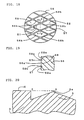
- the roller bar 3 is provided with projections 5 to be explained hereinafter with reference to FIG. 4 showing a front view of the roller bar 3 of FIG. 3.
- the roller bar 3 is formed of a round bar having a diameter of 16mm and provided on the circumferential surface thereof with a plurality of groups of array of projections 5, each group being spaced apart from each other along the axial direction of the roller bar 3 (a lateral direction in FIG. 4) as explained hereinafter and each projection having a shape of pyramid and formed by means of knurling.
- each group of array of projections 5 is consisted of three rows of projections 5 each row being spaced apart along the axial direction of the roller bar 3 as explained hereinafter from each other, and the projections 5 in each row which are sequentially formed along the rotational direction of the roller bar 3 are also spaced apart from each other by a distance which is identical with the distance between the rows.
- axial line of the roller bar 3, it means an imaginary line passing through the rotational center 3b of the roller bar 3 and being parallel with the roller bar 3.
- This "axial line” is indicated in FIG. 2 by a two dots and one dash line depicted between C-C.
- each projection 5 is shaped such that the cross-section thereof is of an isosceles triangle having an angle of about 75 degrees at the tip end 5a (shown by ⁇ ) and a distance of about 1mm between the tip end 5a and the bottom 5b thereof (a vertical distance or height in FIG. 5).
- the height of the tip end 5a of the projection 5 is flush with the level (in the radial direction) of the circumferential surface 6. The distance between neighboring tip ends 5a in the direction of the axial line (lateral direction in FIG.
- each group of array of projections 5 is set to 2.5, and the length of the bottom 5b in the direction of the axial line is set to about 1mm, so that the total width of each group of array of projections 5 consisted of three rows of projections 5 including four bottom portions 5b in the direction of the axial line is about 8.5mm.
- a smooth circumferential surface 6 is also contiguously formed along the rotational direction of the roller bar 3 with a width thereof being 3.5mm in the direction of the axial line.
- a holding member 8 which is provided with a sliding bearing 9 rotatably sustaining this roller bar 3 is constructed as explained below.
- a pressure bar table 7 is integrally mounted on the knife stock 4, and a large number of holding members 8 each having a predetermined width (35mm for instance) are secured, in parallel with the cutting edge of the knife 2, to the pressure bar table 7, i.e. the upper portions of the holding members 8 being cantilevered on the pressure bar table 7.
- the lower portion of each holding member 8 is cut out in a circular shape, and each sliding bearing 9 is inserted into and secured to this circular cut-out portion as shown in FIG. 6 illustrating a perspective view thereof or as shown in FIG. 7 illustrating a partially sectioned view taken along the dashed line F-F of FIG. 3.
- Each sliding bearing 9 is shaped such that the inner diameter thereof is large enough to house the roller bar 3 therein without substantially leaving a space therebetween, i.e. larger than 16mm by a dimension of at most 0.1mm, and that the cross-sectional shape (orthogonal to the axial line of the roller bar 3) thereof is semi-circular having an opening, e.g. on the left side in FIG. 7 wherein the length of the inner circumferential surface 11 of the groove portion 9a is set larger than a half of the circumferential length of the roller bar 3 so as to prevent the roller bar 3 held in each sliding bearing 9 from being ejected therefrom due to its own weight.
- a through-hole to be employed as a water-feed passageway 13 as mentioned hereinafter is formed in the inner circumferential surface 11.
- These holding members 8 are arranged side by side in a sufficient number so as to correspond to the length of a log to be peeled and in such a manner that the groove portions 9a of the bearings 9 neighboring to each other coincide with each other in vertical direction as well as in lateral direction of FIG. 7, and at the same time, are disposed parallel with the cutting edge of the knife 2 as shown in FIGS. 2 and 6. Under this condition, the roller bar 3 is introduced into the groove portion 9a from the right side of FIG. 6. Then, the fixing position of the roller bar 3 to the knife stock 4 is determined so as to set the roller bar 3 to a predetermined position in relative to the knife 2 as explained hereinafter.
- the knife 2 is set to 22 degrees in edge angle and one degree in clearance angle for instance, and then the knife 2 is fixed onto the knife stock 4 in such a way that the cutting edge 2a of the knife 2 is kept at the same level as that of the pivot point of spindle S.
- the position of the roller bar 3 relative to the knife 2 is set and fixed in such a way that the distance "X" between an imaginary cutting line by the knife 2, i.e. a dotted line extending perpendicularly from the cutting edge 2a as shown in FIG. 7 and a portion of the circumferential surface of the roller bar 3 which faces the dotted line is set to 80% of 1mm, i.e. 0.8mm, and that the distance "Y" between a dotted line extending horizontally from the cutting edge 2a as shown in FIG. 7 (hereinafter referred to as a horizontal cutting edge line) and the rotational center 3b of the roller bar 3 is set to 3.8mm.
- the roller bar 3 is preferably arranged such that the rotational center 3b thereof can be moved along the two dots and one dash line shown in FIG. 7, which extends from the cutting edge 2a to pass through the rotational center 3b as the roller bar 3 is so positioned as to peel a veneer having a thickness of 1mm and is slanted upward in relative to the horizontal cutting edge line by an angle of about 11.30 degrees. Therefore, the holding member 8 mounted on the knife stock 4 is enabled to move reciprocatively. Since the structure for allowing this reciprocative motion is the same as that of the conventional veneer lathe, the explanation thereof is omitted herein.
- roller bar 3 Since the roller bar 3 is arranged in this manner, when the positional relationship between the roller bar 3 and the cutting edge 2a is desired to be changed in conformity with a change in thickness of veneer to be produced, e.g. if a veneer having a thickness of 6mm is desired to be produced, the roller bar 3 can be shifted in the right upward direction (FIG. 7) along the aforementioned two dots and one dash line to an extent that the aforementioned distance X becomes 80% of 6mm, i.e. 4.8mm.
- the shaft 3a on both end portions of the roller bar 3 is constructed as follows.
- a couple of holders 10 each constructed in the same manner as that of the holding member 8 provided with the sliding bearing 9 are separately fixed onto the pressure bar table 7 so as to rotatably hold the shaft 3a.
- a sprocket (not shown) is attached to an intermediate portion of the shaft 3a between the couple of the holders 10. This sprocket is engaged with a chain 12 which is adapted to be driven by a motor 18 provided with a torque limiter for limiting a torque to be transmitted.
- the roller bar 3 is designed to be rotated always at a peripheral speed of 60m per minute.
- each holding member 8 is provided with a large number of water-feeding passageways (hereinafter referred to as passageways) 13, each passageway extending from the back surface of the holding member 8 to the inner peripheral wall 11 with which the roller bar 3 disposed inside the groove portion 9a is contacted.
- Each passageway 13 is connected with a tube 14 as shown in FIG. 7.
- Each tube 14 is communicated with a pipe 15 having closed ends and extending, in parallel with the cutting edge of the knife 2, throughout almost the whole length of the holding members 8.
- the pipe 15 is communicated via a tube 17 with a water tank 16 disposed higher than the pipe 15, so that the groove portion 9a is always supplied with water due to the gravitational force of water from the tank 16.
- a couple of female screws 19a which are spaced apart from each other in the direction orthogonal to the moving direction of the knife stock 4 are fixed as a first shifting mechanism to the knife stock 4, each female screw being engaged with a male screw 19b.
- a detector 20 comprising a rotary encoder which is designed to count the number of rotation of the male screw 19b whereby to detect the distance between the rotational center of the log 1 and the cutting edge of knife 2 is attached to the male screw 19b.
- a variable speed driving source 21 comprising a servo-motor for rotating the male screw 19b is attached to the male screw 19b.
- the knife stock 4 is caused to move leftward of FIG. 1 at a desired or predetermined velocity at the occasion of peeling a log, or to move rightward when the peeling is finished thereby to return to the original position.
- a couple of spindles S are adapted to move back and forth against the log 1 by means of a hydraulic cylinder (not shown) acting as a spindle actuating mechanism.
- the spindle S is provided with a center driving device comprising a revolution counter 23 consisting a rotary encoder, etc. for counting the number of revolution per unit time of the spindle S, and a variable speed driving source 24 consisting a DC motor, etc. for rotating the spindle S.
- the spindle S thus constructed is adapted to be controlled such that the log 1 can be rotated always at the same peripheral speed thereby to peel a veneer T with the knife 2 even if the diameter of log 1 is decreased as the knife stock 4 is moved toward the log 1 and the log 1 is peeled by the knife 2, i.e. the spindle S is controlled, by means of a controlling mechanism 22 which is designed to receive signals from the detector 20, such that the number of revolution of the spindle S increases in conformity with a change in distance between the rotational center of the log 1 and the cutting edge of the knife 2. Further, the spindle S is designed to supply, through the core portion of the log, part of the driving power required for the peeling of the log 1. By the way, the aforementioned peripheral speed of log 1 is set to become lower than the peripheral speed of the roller bar 3 (for example, 58m per minute).
- a couple of male screws 30b which are spaced apart from each other in the direction orthogonal to the moving direction of the knife stock 4 are disposed as a second shifting mechanism at a position which is symmetrical, with the spindle S being disposed at the center, to the aforementioned male screws 19b.
- each supporting stand 31 is engaged through a dovetail with a base 32 which is disposed horizontally, so that each supporting stand 31 is allowed to move linearly and horizontally, i.e. each supporting stand 31 is designed to be guided to move in the direction of K (lateral direction) shown in FIG. 1.
- each supporting stand 31 is connected with a detector 33 comprising a rotary encoder for detecting the distance between the rotational center of the log 1 and the circumferential surfaces of rolls 37 and 38 to be explained hereinafter, and with a variable speed driving source 34 comprising a servo-motor.
- a square hollow columnar mounting base member 35 is disposed between the couple of the supporting stands 31 and fixed, through its both ends, to the supporting stands 31.
- a holding member 36 which is L-shaped in side view and whose length in the direction orthogonal to the moving direction of the supporting stands 31 is shorter than that of the columnar mounting base member 35 is fixedly mounted near the center between the supporting stands 31.
- the holding member 36 is disposed so as not to interfere with the movements of a chain 41 and of a timing belt 43 as explained hereinafter.
- a supporting board 39 is secured to the holding member 36.
- a couple of rolls 37 and 38 each having an axial length slightly longer than the log 1 to be peeled are rotatably held through both end portions by bearings 39a mounted on this supporting board 39.
- These rolls 37 and 38 are positioned such that an imaginary horizontal line H-H indicated by a dashed line in FIG. 9 and passing through the rotational center of the log 1 passes through a middle point between the couple of rolls 37 and 38.
- the diameter of each roll 37 or 38 is set to 115mm, while the distance between the rotational centers of these rolls 37 and 38 is set to 145mm.
- a motor 40 is mounted on the surface of the holding member 36.
- the rotation of the motor 40 is transmitted through a chain 41 (shown in two dots and one dash in FIG. 9) to the roll 37.
- the roll 37 is designed to rotate always in the direction indicated by the arrow at a peripheral speed which is set slightly higher than the peripheral speed of the roller bar 3 (for example, 62m per minute).
- a pulse counter 42 for counting the pulse to be generated at the every rotation of an axis is mounted as a revolution-counting mechanism on the bottom surface of the mounting base member 35.
- a toothed gear (not shown) is mounted on the shaft of the pulse counter 42 as well as on the shaft of the roll 38.
- a timing belt 43 (shown as a two dots and one dash line in FIG. 9) is wound around both of these gears so as to transmit the rotation of the roll 38 to the pulse counter 42.
- the signal of rotation of the roll 38 which has been transmitted to the pulse counter 42 is then transmitted to the control mechanism 22, thus making it possible to count the number of revolution per unit time of the log 1 by also taking account of the information of signal from the detector 20 as explained below.
- the controlling mechanism 22 is designed to control each member as explained below.
- the male screw 30b is rotated so as to move the supporting stand 31 away from the log 1 thereby keeping the rolls 37 and 38 away from the log 1, while allowing only the spindle S to contact with the log thereby to rotate the log 1.
- the number of revolution per unit time of the spindle S or the log 1 is calculated by the revolution counter 23, and the signal thereof is received by the controlling mechanism 22.
- the controlling mechanism 22 is actuated to transmit an operation signal (hereinafter referred to as a first operation signal) to the variable speed driving source 21 so as to move the knife stock 4 in such a way that enables a desired constant thickness (for example 6mm) of the veneer to be obtained, i.e. to cause the knife stock 4 to move toward the log 1 at a ratio of 6mm per rotation of the log 1.
- a first operation signal an operation signal (hereinafter referred to as a first operation signal) to the variable speed driving source 21 so as to move the knife stock 4 in such a way that enables a desired constant thickness (for example 6mm) of the veneer to be obtained, i.e. to cause the knife stock 4 to move toward the log 1 at a ratio of 6mm per rotation of the log 1.
- a signal is input manually by an operator to the controlling mechanism 22, whereby the variable speed driving source 34 is actuated so as to move the supporting stand 31 toward the log 1 at a velocity which is faster than that of the knife stock 4.
- the supporting stand 31 is moved to a position where the distance between the rotational center of the log 1 and the circumferential surfaces of rolls 37 and 38 that can be detected from the detector 33 becomes identical with the distance between the rotational center of the log 1 and the cutting edge of the knife 2 that can be obtained from the detector 20 (strictly speaking, a position on the Archimedes' spiral curve taking the thickness of veneer into consideration), a signal to control the supporting stand 31 to move toward the log 1 in the same velocity as that of the knife stock 4 thereafter is transmitted to the variable speed driving source 34.
- the rolls 37 and 38 are moved toward the rotational center of the log 1 while they are always kept pressed onto the circumferential surface of the log 1 being reduced in diameter as it is peeled.
- the roll 38 which is press-contacted with the log 1 is forced to be driven following the rotation of the log 1, and the rotation of this roll 38, i.e. the peripheral speed of the log 1 is transmitted via the timing belt 43 to the pulse counter 42.
- the number of revolution per unit time of the log 1 is calculated every predetermined very short period of time that has been set in advance by the control mechanism 22.
- a signal for moving the knife stock 4 toward the log 1 at a speed of 6mm per every rotation of the log 1 at each number of revolution calculated above (hereinafter referred to as a second operation signal) is calculated by the control mechanism 22.
- the first operation signal is still transmitted to the variable speed driving source 21 and this second operation signal is not yet transmitted to the variable speed driving source 21.
- the control mechanism 22 is actuated to switch the signal to be supplied to the variable speed driving source 21 from the first operation signal which has been initially employed for moving the knife stock 4 to the second operation signal on the basis of which the movement of the knife stock 4 is further continued. After these operation signals are switched in this manner, a signal for moving back the spindle S to separate it from the log 1 is emitted.
- an operation stop signal is transmitted from the control mechanism 22 to the variable speed driving source 21 as well as to the variable speed driving source 34, whereby the movements of the knife stock 4 and the rolls 37 and 38 toward the log 1 are stopped, and then the knife stock 4 and the rolls 37 and 38 moved away from the log.
- the rolls 37 and 38 are kept away from the log, thus allowing only the spindle S to contact with the log 1 so as to rotate the log 1.
- the control mechanism 22 receives signals from the rotation counter 23 and, based on the signals, transmits the first operation signal to the variable speed driving source 21 so as to move the knife stock 4 in such a way that a constant thickness of veneer is assured.
- the spindle S is controlled to increase the number of revolution thereof in conformity with a change in distance between the rotational center of the log 1 and the cutting edge of the knife 2, the number of revolution per unit time of the spindle S increases with the movement of the knife stock 4 toward the log 1.
- the circumferential surface of the roller bar 3 is pressed onto the circumferential surface of the log 1. Since a torque limiter is attached to a motor employed for rotating the roller bar as mentioned above, the peripheral speed of the roller bar 3 is restricted as it is contacted with the log 1, thus becoming almost the same as the peripheral speed of the log 1. A driving force is supplied to the log 1 from the roller bar 3 and also from the spindle S so as to initiate the peeling of log 1 by the knife 2 to produce a veneer.
- This peeling is performed as shown in FIG. 10 illustrating the peeling state of log 1 in a position which is the same as that shown in FIG. 7 and also illustrating a region around the roller bar 3, thus obtaining a veneer T.
- the tip end 5a of the projection 5 is caused to penetrate into the circumferential surface 1a of the log 1 as shown in FIG. 11 illustrating a sectional view taken along the dashed line L-L of FIG. 10. Therefore, the log 1 is forced to rotate by the roller bar 3 under a condition where the circumferential surface 1a of log 1 is caught by the projections 5, thus making it possible to transmit a larger force from the roller bar 3 to the log 1 as compared with the case where the roller bar is entirely formed of a smooth surface.
- the distance in radial direction between the bottom 5b of the projection 5 to the tip end 5a is set to as short as about 1mm, an excessive penetration (or biting) of the tip end 5a into the circumferential surface of log 1 can be avoided. Therefore, a flaw to be formed on the surface of the produced veneer T facing the roller bar 3 is minimal, so that the quality of product such as a plywood that is to be manufactured using this veneer T would not be substantially deteriorated.
- the diameter of the roller bar 3 is as small as 16mm, it becomes possible to press the log at a position immediately before the knife 2 by making use of the smooth surface 6 and the projections 5 of the roller bar 3 as shown in FIG. 10, so that a veneer T which is minimal in lathe check can be obtained.
- the inner wall 11 as well as the circumferential surface of the roller bar 3 can be entirely wetted with water introduced into the groove portion of roller bar 3 through the rotation of the roller bar 3.
- the water introduced in this manner functions as a lubricant and also as a coolant in the rotation of roller bar 3 which is kept in place by the inner wall 11 of the holding member 8.
- a signal is transmitted manually by the operator to the control mechanism 22.
- the control mechanism 22 Upon receiving the signal, the control mechanism 22 is actuated to send a signal to various members so as to actuate these members as explained below.
- variable speed driving source 34 is actuated to move the supporting stand 31 toward the log 1 at a speed which is faster than the moving speed of the knife stock 4.
- the supporting stand 31 is moved to a position where the distance between the rotational center of the log 1 and the circumferential surfaces of rolls 37 and 38 becomes identical with the distance between the rotational center of the log 1 and the cutting edge of the knife 2, so that the rolls 37 and 38 are rendered to press-contact with the circumferential surface of the log 1, the supporting stand 31 is rendered to move, while keeping the rolls 37 and 38 press-contacted with the circumferential surface of the log 1, toward the rotational center of the log 1 at the same speed as that of the knife stock 4.
- the rolls 37 and 38 are press-contacted with the circumferential surface of the log 1, it is possible to prevent the log 1 from being bent by the horizontal force of the knife 2 applied to the log 1 even if the diameter of the log 1 becomes smaller due to the peeling thereof. Further, since the peripheral velocity of the roll 37 is preliminarily set in a manner as mentioned above, a force in the rotational direction of the log 1 is given from the roll 37 to the log 1 while allowing the roll 37 to slip over the circumferential surface of the log 1, whereby supplying part of driving force required for peeling the log.
- the control mechanism 22 When the peeling work is further advanced from the aforementioned state to such an extent that a signal is received from the detector 20 indicating that the distance between the rotational center of the log 1 and the cutting edge of the knife 2 became the aforementioned first distance, the control mechanism 22 is actuated to switch the signal to be supplied to the variable speed driving source 21 from the first operation signal which has been initially employed for moving the knife stock 4 to the second operation signal on the basis of which the movement of the knife stock 4 is further continued. Thereafter, in response to an operation signal from the control mechanism 22, the spindle S is move backward so as to be separated from the log 1.
- the roller bar 3 functions not only as a pressure bar but also as a driving force-transmitting medium for transmitting at least part of driving force required for the peeling of log to the log.
- the diameter of the roller bar is set to 16mm.
- the diameter of the roller bar is not more than 30mm, it is possible to apply the roller bar to a position immediately before the knife so as to effectively press the log, thus enabling the roller bar to function as a pressure bar and also as a medium to transmit a driving force to the log.
- the thickness of veneer to be produced is relatively thick, e.g. 10mm or so, it may be more preferable to set the diameter of the roller bar to 20mm or so.
- the thickness of veneer to be produced is relatively thin, e.g. no more than 5mm, it may be more preferable to set the diameter of the roller bar to 16mm or so.
- the distance in the direction orthogonal to the rotating direction of the log i.e. the distance X shown in FIG. 7 is selected to be not more than 85% of the thickness of veneer to be produced, a veneer which is minimal in lathe check can be obtained.
- Table 1 X in FIG. 7 (ratio (%) to the thickness of veneer) B 80 85 90 95 16 ⁇ ⁇ ⁇ ⁇ 20 ⁇ ⁇ ⁇ ⁇ 25 ⁇ ⁇ ⁇ ⁇ 30 ⁇ ⁇ ⁇ ⁇ 40 ⁇ ⁇ ⁇ ⁇ ⁇ (Note) B: The diameter of the roller bar (mm) ⁇ : Minimal in lathe check and the surface of veneer is also minimal in roughness ⁇ : More or less prominent in lathe check and the surface of veneer is also somewhat prominent in roughness ⁇ : Prominent in lathe check and the surface of veneer is also Prominent in roughness.
- the roller bar according to this invention is constructed to function not only as a pressure bar but also as a driving force-transmitting medium for transmitting at least part of driving force required for the peeling of log to the log, thus making it possible to overcome the problems accompanied with the conventional apparatus. Furthermore, since these functions can be achieved by a single roller bar, the cost for the apparatus can be saved.
- the circumferential surface of the roller bar is provided with a plurality of smooth surfaces and a plurality of roughened surfaces, each having a predetermined width, which are successively formed along the direction of axial line of the roller bar, it is possible to prevent the portion of the inner wall 11 which is contacted with the smooth surface of the roller bar from being erased substantially, thus making it possible to maintain the roller bar in a fixed position and to manufacture a veneer T excellent in quality under a desired condition.
Landscapes
- Life Sciences & Earth Sciences (AREA)
- Engineering & Computer Science (AREA)
- Wood Science & Technology (AREA)
- Forests & Forestry (AREA)
- Manufacturing & Machinery (AREA)
- Mechanical Engineering (AREA)
- Manufacture Of Wood Veneers (AREA)
- Sawing (AREA)
Claims (3)
- Dérouleuse comprenant:- une lame (2) pour découper des bandes à partir d'un tronc (1) qui est bloquée de manière pivotable contre un support-lame (4) ;- une barre (3) disposée pour exercer une pression sur une surface circonférentielle du tronc (1) en amont de ladite lame (2) dans le sens de rotation du tronc (1) ;- un palier à glissement (9) fixé audit support-lame (4), dans lequel repose de manière pivotable ladite barre (3), ce palier à glissement (9) présentant une section transversale de forme semi-circulaire et ouvrant vers le tronc (1) si la section transversale est coupée orthogonalement par rapport à une ligne axiale de ladite barre (3), avec le palier à glissement étant monté de manière à ce qu'il a vue, via ladite barre, sur le tronc (1) à découper ; et- moyens d'entraînement (18, 12) pour mettre en rotation ladite barre (3) qui repose dans ledit palier à glissement (9),caractérisée en ce que la surface circonférentielle de ladite barre (3) comprend une pluralité de tronçons circonférentiels lisses (6) dont chacun a une largeur arbitraire dans la direction de l'axe de ladite barre (3) et est contigu dans la direction de rotation de ladite barre (3), et une pluralité de tronçons comportant quelques éléments en saillie (5) formés entre les tronçons circonférentiels lisses (6) dans la direction de l'axe de ladite barre (3), lesdits éléments en saillie (5) présentant une hauteur qui ne dépasse pas la surface circonférentielle de ladite barre (3).
- Dérouleuse selon la revendication 1, caractérisée en ce que lesdits éléments en saillie (5) sont formés sur la surface circonférentielle de ladite barre (3) de manière à ce que le niveau des pointes desdits éléments en saillie (5) dans la direction radiale de ladite barre (3) est à fleur de la surface circonférentielle de la barre (3).
- Dérouleuse selon l'une des revendications 1 ou 2, caractérisée en ce que lesdits éléments en saillie (5) sont formés sur la surface circonférentielle de ladite barre (3) de manière à ce que le niveau des pointes desdits éléments en saillie (5) dans la direction radiale de ladite barre (3) est inférieur à la surface circonférentielle de la barre (3).
Applications Claiming Priority (3)
| Application Number | Priority Date | Filing Date | Title |
|---|---|---|---|
| JP21912797 | 1997-07-29 | ||
| JP219127/97 | 1997-07-29 | ||
| JP21912797 | 1997-07-29 |
Publications (3)
| Publication Number | Publication Date |
|---|---|
| EP0894585A2 EP0894585A2 (fr) | 1999-02-03 |
| EP0894585A3 EP0894585A3 (fr) | 2003-07-02 |
| EP0894585B1 true EP0894585B1 (fr) | 2006-06-07 |
Family
ID=16730671
Family Applications (1)
| Application Number | Title | Priority Date | Filing Date |
|---|---|---|---|
| EP98113738A Expired - Lifetime EP0894585B1 (fr) | 1997-07-29 | 1998-07-23 | Dérouleuse |
Country Status (10)
| Country | Link |
|---|---|
| US (1) | US5971045A (fr) |
| EP (1) | EP0894585B1 (fr) |
| KR (1) | KR100283509B1 (fr) |
| CN (1) | CN1085133C (fr) |
| CA (1) | CA2244267C (fr) |
| DE (1) | DE69834775T2 (fr) |
| ID (1) | ID20639A (fr) |
| MY (1) | MY112370A (fr) |
| NZ (1) | NZ331114A (fr) |
| TW (1) | TW369469B (fr) |
Families Citing this family (13)
| Publication number | Priority date | Publication date | Assignee | Title |
|---|---|---|---|---|
| CN1091406C (zh) * | 2000-04-20 | 2002-09-25 | 河北省文安县安里屯冷拉钢材厂 | 木材无卡轴旋切机 |
| JP4080757B2 (ja) * | 2001-02-06 | 2008-04-23 | 株式会社名南製作所 | ベニヤレース |
| US7108031B1 (en) * | 2002-01-31 | 2006-09-19 | David Secrest | Method of making patterns in wood and decorative articles of wood made from said method |
| US7370680B2 (en) * | 2006-03-03 | 2008-05-13 | Carlos Alberto Fernando Fezer | Lathe having movable spindles and method |
| DE102006027271B4 (de) * | 2006-06-09 | 2008-06-12 | Albrecht Bäumer GmbH & Co.KG | Verfahren zum Anfahren einer Schälvorrichtung für eine Folie von einem Materialblock |
| FI123331B (fi) * | 2011-02-09 | 2013-02-28 | Raute Oyj | Viilujen sorvauslaite |
| US20140261891A1 (en) * | 2013-03-13 | 2014-09-18 | Shaw Industries Group, Inc. | Cutting Knives, Systems And Methods For Forming A Predetermined Pattern Into A Wood Layer |
| CN107398976A (zh) * | 2017-09-11 | 2017-11-28 | 四川麦笠机械设备有限公司 | 一种带齿辊以及旋切装置,以及木质单板制造方法 |
| CN108705638B (zh) * | 2018-05-17 | 2020-12-11 | 漳州市炯辉机械有限公司 | 一种高质量旋切流水线的供料机构 |
| CN109318329A (zh) * | 2018-12-02 | 2019-02-12 | 广西容县美坚机械厂 | 一种原木数控无卡旋切一体机的单双压辊总成结构 |
| CN111283835B (zh) * | 2020-03-10 | 2022-01-04 | 重庆市奉节县竹轩农业开发有限公司 | 一种竹节刮皮装置 |
| CN114683369B (zh) * | 2022-04-21 | 2023-05-26 | 山东百圣源集团有限公司 | 原木板材自动旋转碎板装置 |
| CN117621131B (zh) * | 2024-01-25 | 2024-04-09 | 安徽农业大学 | 一种实木旋切加工用上料机械手及方法 |
Family Cites Families (14)
| Publication number | Priority date | Publication date | Assignee | Title |
|---|---|---|---|---|
| US3480053A (en) * | 1967-09-07 | 1969-11-25 | Melvin M Whipple | Pressure roll drives |
| CA895132A (en) * | 1970-03-05 | 1972-03-14 | Her Majesty In Right Of Canada As Represented By The Minister Of Fisheri Es And Oceans | Veneer machine roller pressure bar assembly |
| JPS5391499A (en) * | 1977-01-21 | 1978-08-11 | Meinan Machinery Works | Veneer lathe |
| US4602663A (en) * | 1984-08-07 | 1986-07-29 | The Coe Manufacturing Co. | Veneer lathe with powered nose bar roll of large diameter |
| JPH0628845B2 (ja) * | 1986-03-24 | 1994-04-20 | 株式会社名南製作所 | ベニヤレース |
| US4790360A (en) * | 1987-10-26 | 1988-12-13 | Forintek Canada Corp. | Wood tenderizing apparatus and method |
| JP2759357B2 (ja) * | 1989-11-15 | 1998-05-28 | 株式会社名南製作所 | 外周駆動型ベニヤレースに於ける駆動ロールの加圧方法 |
| JP2805170B2 (ja) * | 1990-07-06 | 1998-09-30 | 株式会社名南製作所 | 可センターレス式ベニヤレースの歩送り方法 |
| US5333658A (en) * | 1993-08-26 | 1994-08-02 | Premier Gear & Machine Works | Veneer lathe |
| JPH07214516A (ja) * | 1994-02-08 | 1995-08-15 | Uroko Seisakusho Co Ltd | ベニヤレースにおける原木駆動ロール装置 |
| JPH08132411A (ja) * | 1994-11-07 | 1996-05-28 | Meinan Mach Works Inc | 可センターレス式ベニヤレースに於ける歩送りの切上げ方法 |
| JP3676535B2 (ja) * | 1996-04-22 | 2005-07-27 | 株式会社名南製作所 | ベニヤレースにおけるバックアップロールの歩送り制御方法及びベニヤレースにおけるバックアップロール装置 |
| US5715879A (en) * | 1996-07-15 | 1998-02-10 | Jones; William F. | Nose bar and drive assembly |
| JP3665162B2 (ja) * | 1996-12-20 | 2005-06-29 | 株式会社名南製作所 | ベニヤレース |
-
1998
- 1998-07-17 TW TW087111663A patent/TW369469B/zh not_active IP Right Cessation
- 1998-07-20 MY MYPI98003300A patent/MY112370A/en unknown
- 1998-07-23 DE DE69834775T patent/DE69834775T2/de not_active Expired - Fee Related
- 1998-07-23 EP EP98113738A patent/EP0894585B1/fr not_active Expired - Lifetime
- 1998-07-27 KR KR1019980030226A patent/KR100283509B1/ko not_active IP Right Cessation
- 1998-07-27 US US09/122,868 patent/US5971045A/en not_active Expired - Lifetime
- 1998-07-28 NZ NZ331114A patent/NZ331114A/xx not_active IP Right Cessation
- 1998-07-28 ID IDP981053A patent/ID20639A/id unknown
- 1998-07-28 CA CA002244267A patent/CA2244267C/fr not_active Expired - Lifetime
- 1998-07-29 CN CN98117572A patent/CN1085133C/zh not_active Expired - Fee Related
Also Published As
| Publication number | Publication date |
|---|---|
| CN1085133C (zh) | 2002-05-22 |
| DE69834775T2 (de) | 2007-05-16 |
| US5971045A (en) | 1999-10-26 |
| DE69834775D1 (de) | 2006-07-20 |
| KR19990014216A (ko) | 1999-02-25 |
| EP0894585A2 (fr) | 1999-02-03 |
| KR100283509B1 (ko) | 2001-05-02 |
| CA2244267A1 (fr) | 1999-01-29 |
| ID20639A (id) | 1999-02-04 |
| TW369469B (en) | 1999-09-11 |
| MY112370A (en) | 2001-05-31 |
| EP0894585A3 (fr) | 2003-07-02 |
| CN1209378A (zh) | 1999-03-03 |
| CA2244267C (fr) | 2007-05-29 |
| NZ331114A (en) | 2000-04-28 |
Similar Documents
| Publication | Publication Date | Title |
|---|---|---|
| EP0894585B1 (fr) | Dérouleuse | |
| KR100276942B1 (ko) | 베니어선반 | |
| US20070074787A1 (en) | Veneer lathe and method of cutting wood block by the veneer lathe | |
| JPH10151599A (ja) | テ−プ、とりわけ磁気テ−プの切断装置のためのカッタ−送り込み機構 | |
| CA2028624C (fr) | Appareil et methode pour couper et/ou biseauter un tube de plastique | |
| US6357496B1 (en) | Veneer lathe | |
| KR100730452B1 (ko) | 베니어 레이스 | |
| US4596170A (en) | Bar stock guiding device for use with automatic latches | |
| US4936130A (en) | Apparatus for altering the cross-sectional shape of can bodies | |
| US5217724A (en) | Apparatus for the in-line cropping and/or chamfering of a plastic tube | |
| KR200343562Y1 (ko) | 칼국수용 전분시트 제조장치 | |
| JP4051084B2 (ja) | ベニヤレースでの原木切削方法およびベニヤレース | |
| JP2002046109A (ja) | ベニヤレース | |
| JP4197769B2 (ja) | ベニヤレース | |
| JP7075422B2 (ja) | シート供給方法及びシート供給装置 | |
| KR830002074B1 (ko) | 베니어판 선반 | |
| KR810001770B1 (ko) | 베니어 선반 | |
| SU1079438A1 (ru) | Лущильный станок | |
| JP2620703B2 (ja) | ベニヤレース | |
| CN118081384A (zh) | 一种螺栓倒角与打标一体装置 | |
| JPH1159868A (ja) | 部品供給装置 | |
| JPS63231903A (ja) | ベニヤレ−ス |
Legal Events
| Date | Code | Title | Description |
|---|---|---|---|
| PUAI | Public reference made under article 153(3) epc to a published international application that has entered the european phase |
Free format text: ORIGINAL CODE: 0009012 |
|
| AK | Designated contracting states |
Kind code of ref document: A2 Designated state(s): AT BE CH CY DE DK ES FI FR GB GR IE IT LI LU MC NL PT SE |
|
| AX | Request for extension of the european patent |
Free format text: AL;LT;LV;MK;RO;SI |
|
| PUAL | Search report despatched |
Free format text: ORIGINAL CODE: 0009013 |
|
| AK | Designated contracting states |
Designated state(s): AT BE CH CY DE DK ES FI FR GB GR IE IT LI LU MC NL PT SE |
|
| AX | Request for extension of the european patent |
Extension state: AL LT LV MK RO SI |
|
| 17P | Request for examination filed |
Effective date: 20040102 |
|
| AKX | Designation fees paid |
Designated state(s): DE FI IT |
|
| 17Q | First examination report despatched |
Effective date: 20050114 |
|
| GRAP | Despatch of communication of intention to grant a patent |
Free format text: ORIGINAL CODE: EPIDOSNIGR1 |
|
| GRAS | Grant fee paid |
Free format text: ORIGINAL CODE: EPIDOSNIGR3 |
|
| GRAA | (expected) grant |
Free format text: ORIGINAL CODE: 0009210 |
|
| AK | Designated contracting states |
Kind code of ref document: B1 Designated state(s): DE FI IT |
|
| REF | Corresponds to: |
Ref document number: 69834775 Country of ref document: DE Date of ref document: 20060720 Kind code of ref document: P |
|
| PLBE | No opposition filed within time limit |
Free format text: ORIGINAL CODE: 0009261 |
|
| STAA | Information on the status of an ep patent application or granted ep patent |
Free format text: STATUS: NO OPPOSITION FILED WITHIN TIME LIMIT |
|
| 26N | No opposition filed |
Effective date: 20070308 |
|
| PGFP | Annual fee paid to national office [announced via postgrant information from national office to epo] |
Ref country code: DE Payment date: 20070719 Year of fee payment: 10 |
|
| PGFP | Annual fee paid to national office [announced via postgrant information from national office to epo] |
Ref country code: IT Payment date: 20070616 Year of fee payment: 10 |
|
| PG25 | Lapsed in a contracting state [announced via postgrant information from national office to epo] |
Ref country code: DE Free format text: LAPSE BECAUSE OF NON-PAYMENT OF DUE FEES Effective date: 20090203 |
|
| PG25 | Lapsed in a contracting state [announced via postgrant information from national office to epo] |
Ref country code: IT Free format text: LAPSE BECAUSE OF NON-PAYMENT OF DUE FEES Effective date: 20080723 |
|
| PGFP | Annual fee paid to national office [announced via postgrant information from national office to epo] |
Ref country code: FI Payment date: 20160713 Year of fee payment: 19 |
|
| PG25 | Lapsed in a contracting state [announced via postgrant information from national office to epo] |
Ref country code: FI Free format text: LAPSE BECAUSE OF NON-PAYMENT OF DUE FEES Effective date: 20170723 |