EP0893935B1 - Montagegehäuse für einen elektroakustischen Wandler - Google Patents
Montagegehäuse für einen elektroakustischen Wandler Download PDFInfo
- Publication number
- EP0893935B1 EP0893935B1 EP98110703A EP98110703A EP0893935B1 EP 0893935 B1 EP0893935 B1 EP 0893935B1 EP 98110703 A EP98110703 A EP 98110703A EP 98110703 A EP98110703 A EP 98110703A EP 0893935 B1 EP0893935 B1 EP 0893935B1
- Authority
- EP
- European Patent Office
- Prior art keywords
- reception
- converter
- sound entry
- sound
- acceptor plate
- Prior art date
- Legal status (The legal status is an assumption and is not a legal conclusion. Google has not performed a legal analysis and makes no representation as to the accuracy of the status listed.)
- Expired - Lifetime
Links
Images

Classifications
-
- H—ELECTRICITY
- H04—ELECTRIC COMMUNICATION TECHNIQUE
- H04R—LOUDSPEAKERS, MICROPHONES, GRAMOPHONE PICK-UPS OR LIKE ACOUSTIC ELECTROMECHANICAL TRANSDUCERS; ELECTRIC HEARING AIDS; PUBLIC ADDRESS SYSTEMS
- H04R1/00—Details of transducers, loudspeakers or microphones
- H04R1/02—Casings; Cabinets ; Supports therefor; Mountings therein
- H04R1/021—Casings; Cabinets ; Supports therefor; Mountings therein incorporating only one transducer
-
- H—ELECTRICITY
- H04—ELECTRIC COMMUNICATION TECHNIQUE
- H04R—LOUDSPEAKERS, MICROPHONES, GRAMOPHONE PICK-UPS OR LIKE ACOUSTIC ELECTROMECHANICAL TRANSDUCERS; ELECTRIC HEARING AIDS; PUBLIC ADDRESS SYSTEMS
- H04R1/00—Details of transducers, loudspeakers or microphones
- H04R1/02—Casings; Cabinets ; Supports therefor; Mountings therein
Definitions
- the present invention relates to a mounting housing for receiving a cylindrical electro-acoustic transducer having on its back non-rotationally symmetrical contacting surfaces for automatic contacting, connection pins and at least one non-rotationally symmetrically arranged sound inlet opening.
- the object of the present invention is therefore to provide a mounting housing for electro-acoustic transducers of the type mentioned above, with a simple way reliable automatic contact is made possible.
- a mounting housing comprises a receiving plate for the transducer with two receiving bores for guiding the connecting pins, at least one radially oriented groove, which is located below a sound inlet opening, and by two Receiving holes, which are located below the contacting surfaces for automatic contacting, in which coil springs are held, which protrude on the side opposite to the side adjacent to the acoustic transducer, and a pluggable over the acoustic transducer cap whose edge with the edge of Receiving plate can be latched, and which has at least one sound inlet bore, which adjoins a sound inlet groove of the receiving plate.
- the mounting housing according to the present invention provides a stable, vibration-proof contacting principle with a uniform contact force over large height tolerances. Another advantage is that there is little risk of plastic deformation. For microphones with rearward sound inlet opening there is the possibility of hand soldering-free automatic contacting with a defined acoustic behavior in that the existing connection pins are used to uniquely define the position of the electroacoustic transducer.
- An expedient development of the present invention is characterized in that the end of the spiral spring, which is in contact with the transducer, has a larger diameter than the remaining part of the spiral spring, and that the inner dimensions of the receiving bores for the coil springs are adapted to the outer dimensions of the coil springs ,
- the in the FIGS. 1 to 3 shown electroacoustic transducer in the present case a microphone capsule, has front rotationally symmetrical sound inlet openings 5 and a rear non-rotationally symmetrical sound inlet opening 6. Furthermore, the microphone capsule shown has on the back pins 4 and solder pads 3 for other types of connections such as leaf springs.
- This receiving plate 7 has corresponding holes 13 for receiving the pins 4. This causes a fixed orientation of the microphone capsule to the receiving plate 7 causes. At defined intervals to these pins 4 contacting surfaces are then realized on the rear wall of the microphone capsule.
- the sound inlet groove 9 in the receiving plate comes to lie exactly below the rear sound inlet opening 6.
- a cap 8 Via the receiving plate 7 with the microphone capsule 1, a cap 8, which e.g. made of rubber, to be inverted to achieve a seal against unwanted sound entrances.
- the cap 8 has a sound inlet bore 10, which is arranged such that it adjoins the sound inlet groove 9 in the receiving plate 7, so that a continuous rear sound inlet opening is ensured.
- spiral springs 11 At one end with a larger diameter. Then, for contacting with the solder pads 3 of the microphone capsule 1, the larger-diameter ends are used, and the smaller-diameter ends are used for contacting to the outside.
- the larger-diameter ends are used, and the smaller-diameter ends are used for contacting to the outside.
- bore is adapted to these diameters, so that in this case results in a self-retaining spring contact during assembly.
Landscapes
- Physics & Mathematics (AREA)
- Engineering & Computer Science (AREA)
- Acoustics & Sound (AREA)
- Signal Processing (AREA)
- Details Of Audible-Bandwidth Transducers (AREA)
- Audible-Bandwidth Dynamoelectric Transducers Other Than Pickups (AREA)
- Piezo-Electric Transducers For Audible Bands (AREA)
- Transducers For Ultrasonic Waves (AREA)
- Electrostatic, Electromagnetic, Magneto- Strictive, And Variable-Resistance Transducers (AREA)
- Headphones And Earphones (AREA)
Description
- Die vorliegende Erfindung betrifft ein Montagegehäuse zur Aufnahme eines zylinderförmigen elektroakustischen Wandlers, der auf seiner Rückseite nicht rotationssymmetrische Kontaktierungsflächen für eine automatische Kontaktierung, Anschlusspins und mindestens eine nicht rotationssymmetrisch angeordnete Schalleintrittsöffnung aufweist.
- Die automatische Kontaktierung derartiger Wandler erfolgt in der Regel mittels einer Leitgummikontaktierung oder einer Blattfederkontaktierung und insbesondere bei Druckgradientenmikrofonen, die zusätzlich zu rotationssymmetrischen Schalleintrittsöffnungen auf der Vorderseite im allgemeinen nicht rotationssymmetrische Schalleintrittsöffnungen in der rückseitigen Leiterplatte besitzen, durch Handlöten von Blattfedern auf den Wandler.
- Derartige Kontaktierungen besitzen über große Höhentoleranzen keine gleichmäßige Kontaktkraft und es besteht die Gefahr einer plastischen Federverformung bei der Montage und beim Handling. Auch ist die Montage selbst, insbesondere bei Druckgradientenmikrofonen, schwierig.
- Aufgabe der vorliegenden Erfindungsmeldung ist es daher ein Montagegehäuse für elektroakustische Wandler der eingangs genannten Art anzugeben, mit der auf einfache Weise eine zuverlässige automatische Kontaktierung ermöglicht wird.
- Diese Aufgabe wird durch Anspruch 1 gelöst.
- Gemäß der vorliegenden Erfindung umfasst ein Montagegehäuse eine Aufnahmeplatte für den Wandler mit zwei Aufnahmebohrungen zur Führung der Anschlussstifte, mindestens einer radial ausgerichteten Nut, welche sich unterhalb einer Schalleintrittsöffnung befindet, und durch zwei Aufnahmebohrungen, welche sich unterhalb der Kontaktierungsflächen für die automatische Kontaktierung befinden, in denen Spiralfedern gehalten sind, die auf der Seite, die der dem akustischen Wandler benachbarten Seite gegenüberliegt, herausragen, und eine über den akustischen Wandler steckbare Abdeckkappe, deren Rand mit dem Rand der Aufnahmeplatte verrastbar ist, und welche mindestens eine Schalleintrittsbohrung aufweist, die sich an eine Schalleintrittsnut der Aufnahmeplatte anschließt.
- Das Montagegehäuse gemäß der vorliegenden Erfindung bietet ein stabiles, erschütterungssicheres Kontaktierungsprinzip mit einer gleichmäßigen Kontaktkraft über große Höhentoleranzen. Ein weiterer Vorteil besteht darin, dass nur eine geringe Gefahr einer plastischen Verformung besteht. Für Mikrofone mit rückwärtiger Schalleintrittsöffnung ergibt sich die Möglichkeit handlötungsfreier automatischer Kontaktierung bei definiertem akustischen Verhalten dadurch, dass die vorhandenen Anschlusspins zur eindeutigen Definition der Lage des elektroakustischen Wandlers verwendet werden.
- Eine zweckmäßige Weiterbildung der vorliegenden Erfindung ist dadurch gekennzeichnet, dass das Ende der Spiralfeder, welches mit dem Wandler in Kontakt steht, einen größeren Durchmesser aufweist als der übrige Teil der Spiralfeder, und dass die Innenabmessungen der Aufnahmebohrungen für die Spiralfedern den Außenabmessungen der Spiralfedern angepasst sind.
- Der Einsatz dieser selbsthaltenden Spiralfedern ergibt zusätzlich den Vorteil einer einfachen Montage.
- Nachstehend wird die Erfindung anhand eines in der Zeichnung dargestellten Ausführungsbeispiels näher beschrieben.
- Es zeigen
-
Figur 1 die Draufsicht auf einen elektroakustischen Wandler zur Verwendung in Verbindung mit einem Montagegehäuse gemäß der vorliegenden Erfindung, -
Figur 2 eine Seitenansicht des inFigur 1 dargestellten elektroakustischen Wandlers, -
Figur 3 eine Rückansicht des inFigur 1 dargestellten elektroakustischen Wandlers, -
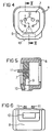
Figur 4 eine Rückansicht eines erfindungsgemäßen Montagegehäuses, -
Figur 5 einen Querschnitt durch das inFigur 4 gezeigte Montagegehäuse, und -
Figur 6 eine Seitenansicht des inFigur 4 gezeigten Montagegehäuses. - Der in den
Figuren 1 bis 3 gezeigte elektroakustische Wandler, im vorliegenden Fall eine Mikrofonkapsel, besitzt vordere rotationssymmetrische Schalleintrittsöffnungen 5 und eine hintere nicht rotationssymmetrische Schalleintrittsöffnung 6. Weiterhin besitzt die dargestellte Mikrofonkapsel auf der Rückseite Anschlußstifte 4 und Lötpads 3 für andere Anschlußarten z.B. für Blattfedern. - Das Montagegehäuse gemäß der vorliegenden Erfindung zur Aufnahme der in den
Figuren 1 bis 3 dargestellten Mikrofonkapsel besitzt eine Aufnahmeplatte 7. Diese Aufnahmeplatte 7 besitzt entsprechende Bohrungen 13 zur Aufnahme der Anschlußstifte 4. Dadurch wird eine feste Orientierung der Mikrofonkapsel zur Aufnahmeplatte 7 bewirkt. In definierten Abständen zu diesen Anschlußstiften 4 sind dann Kontaktierungsflächen auf der Rückwand der Mikrofonkapsel realisiert. - Dadurch kommt die Schalleintrittsnut 9 in der Aufnahmeplatte exakt unterhalb der hinteren Schalleintrittsöffnung 6 zu liegen. Gleichzeitig kommen die Spiralfedern 11, welche in den Bohrungen 12 gehalten werden, unter den Lötpads 3 für unterschiedliche Anschlußarten zu liegen, so daß eine sichere Kontaktierung gewährleistet ist.
- Über die Aufnahmeplatte 7 mit der Mikrofonkapsel 1 kann eine Abdeckkappe 8, welche z.B. aus Gummi besteht, gestülpt werden, um eine Abdichtung gegen unerwünschte Schalleintritte zu erreichen. Die Abdeckkappe 8 besitzt eine Schalleintrittsbohrung 10, welche derart angeordnet ist, daß sie sich an die Schalleintrittsnut 9 in der Aufnahmeplatte 7 anschließt, so daß eine durchgehende hintere Schalleintrittsöffnung gewährleistet ist.
- Besonders vorteilhaft ist es, die Spiralfedern 11 an einem Ende mit einem größeren Durchmesser auszubilden. Dann werden zur Kontaktierung mit den Lötpads 3 der Mikrofonkapsel 1 die Enden mit dem größeren Durchmesser verwendet, und zur Kontaktierung nach außen werden die Enden mit dem kleineren Durchmesser verwendet. Bei der Verwendung derartig ausgebildeter Spiralfedern ist die Bohrung diesen Durchmessern angepaßt, so daß sich in diesem Fall bei der Montage eine selbsthaltende Federkontaktierung ergibt.
Claims (2)
- Montagegehäuse zur Aufnahme eines zylinderförmigen elektroakustischen Wandlers (1) der auf seiner Rückseite nicht rotationssymmetrische Kontaktierungsflächen (3) für eine automatische Kontaktierung, Anschlussstifte (4) und mindestens eine nicht rotationssymmetrisch angeordnete Schalleintrittsöffnung (6) aufweist, gekennzeichnet durch
eine Aufnahmeplatte (7) für den Wandler (1) mit zwei Aufnahmebohrungen (13) zur Führung der Anschlussstifte (4), mindestens einer radial ausgerichteten Schalleintristtsnut (9), welche sich unterhalb der Schalleintrittsöffnung (6) des elektroakustischen Wandlers befindet, und durch zwei Aufnahmebohrungen (12), welche sich unterhalb der Kontaktierungsflächen (3) des elektroakustischen Wandlers für die automatische Kontaktierung befinden, in denen Spiralfedern (11) gehalten sind, die auf der Seite, die der dem akustischen Wandler (1) benachbarten Seite gegenüberliegt, herausragen, und
eine über den akustischen Wandler (1) steckbare Abdeckkappe (8), deren Rand mit dem Rand der Aufnahmeplatte (7) verrastbar ist, und welche mindestens eine Schalleintrittsbohrung (10) aufweist, die sich an die Schalleintrittsnut (9) der Aufnahmeplatte (7) anschließt. - Montagegehäuse nach Anspruch 1,
dadurch gekennzeichnet,
dass das Ende der Spiralfeder (11), welches mit dem Wandler (1) in Kontakt steht, einen größeren Durchmesser aufweist als der übrige Teil der Spiralfeder (11), und
dass die Innenabmessungen der Aufnahmebohrungen (12) für die Spiralfedern (11) den Außenabmessungen der Spiralfedern (11) angepasst sind.
Applications Claiming Priority (2)
| Application Number | Priority Date | Filing Date | Title |
|---|---|---|---|
| DE29713202U DE29713202U1 (de) | 1997-07-24 | 1997-07-24 | Montagegehäuse für elektroakustischen Wandler |
| DE29713202U | 1997-07-24 |
Publications (3)
| Publication Number | Publication Date |
|---|---|
| EP0893935A2 EP0893935A2 (de) | 1999-01-27 |
| EP0893935A3 EP0893935A3 (de) | 2006-05-03 |
| EP0893935B1 true EP0893935B1 (de) | 2010-12-15 |
Family
ID=8043646
Family Applications (1)
| Application Number | Title | Priority Date | Filing Date |
|---|---|---|---|
| EP98110703A Expired - Lifetime EP0893935B1 (de) | 1997-07-24 | 1998-06-10 | Montagegehäuse für einen elektroakustischen Wandler |
Country Status (5)
| Country | Link |
|---|---|
| US (1) | US5995637A (de) |
| EP (1) | EP0893935B1 (de) |
| JP (1) | JP3056041U (de) |
| AT (1) | ATE492124T1 (de) |
| DE (2) | DE29713202U1 (de) |
Families Citing this family (5)
| Publication number | Priority date | Publication date | Assignee | Title |
|---|---|---|---|---|
| DE29713202U1 (de) * | 1997-07-24 | 1997-12-18 | Siemens AG, 80333 München | Montagegehäuse für elektroakustischen Wandler |
| JP4402471B2 (ja) | 2004-02-05 | 2010-01-20 | スター精密株式会社 | 電気音響変換器 |
| US9042606B2 (en) * | 2006-06-16 | 2015-05-26 | Board Of Regents Of The Nevada System Of Higher Education | Hand-based biometric analysis |
| US8655084B2 (en) * | 2009-06-23 | 2014-02-18 | Board Of Regents Of The Nevada System Of Higher Education, On Behalf Of The University Of Nevada, Reno | Hand-based gender classification |
| US20180173339A1 (en) * | 2015-06-19 | 2018-06-21 | Huawei Technologies Co., Ltd. | User Equipment |
Family Cites Families (6)
| Publication number | Priority date | Publication date | Assignee | Title |
|---|---|---|---|---|
| US2833868A (en) * | 1953-05-07 | 1958-05-06 | Maico Electronics Inc | Microphone mounting for hearing aids |
| FR2402374A1 (fr) * | 1977-08-30 | 1979-03-30 | Thomson Brandt | Dispositif de montage d'un microphone incorpore dans un appareil d'enregistrement sonore et appareil a microphone incorpore |
| US4306121A (en) * | 1979-04-12 | 1981-12-15 | Instrument Systems Corporation | Electro-acoustic transducer assembly |
| US4295009A (en) * | 1980-03-07 | 1981-10-13 | Amp Incorporated | Piezoelectric audio transducer mounting and electrical connector |
| SE440581B (sv) * | 1983-12-22 | 1985-08-05 | Ericsson Telefon Ab L M | Forfarande for framstellning av elektroakustiska omvandlare med slutet resonansrum, foretredesvis mikrofoner, samt elektroakustisk omvandlare framstelld enligt forfarandet |
| DE29713202U1 (de) * | 1997-07-24 | 1997-12-18 | Siemens AG, 80333 München | Montagegehäuse für elektroakustischen Wandler |
-
1997
- 1997-07-24 DE DE29713202U patent/DE29713202U1/de not_active Expired - Lifetime
-
1998
- 1998-06-10 DE DE59814476T patent/DE59814476D1/de not_active Expired - Lifetime
- 1998-06-10 AT AT98110703T patent/ATE492124T1/de active
- 1998-06-10 EP EP98110703A patent/EP0893935B1/de not_active Expired - Lifetime
- 1998-06-30 US US09/106,775 patent/US5995637A/en not_active Expired - Lifetime
- 1998-07-21 JP JP1998005415U patent/JP3056041U/ja not_active Expired - Lifetime
Also Published As
| Publication number | Publication date |
|---|---|
| JP3056041U (ja) | 1999-02-02 |
| DE59814476D1 (de) | 2011-01-27 |
| ATE492124T1 (de) | 2011-01-15 |
| DE29713202U1 (de) | 1997-12-18 |
| EP0893935A2 (de) | 1999-01-27 |
| US5995637A (en) | 1999-11-30 |
| EP0893935A3 (de) | 2006-05-03 |
Similar Documents
| Publication | Publication Date | Title |
|---|---|---|
| DE2939479C2 (de) | ||
| DE2258118B2 (de) | Hörgerät | |
| CH664057A5 (de) | Hoergeraet. | |
| EP0136643A2 (de) | Hörgerät | |
| DE2330367A1 (de) | Elektrostatischer wandler | |
| EP0285842A1 (de) | Hörgerät, dessen Bauelemente in einem Hörgerätgehäuse gehaltert sind | |
| DE69704897T2 (de) | Piezoelektrisch-akoustischer Wandler | |
| DE60025590T2 (de) | Anordnung mit einem elektroakustischen wandler dessen anschlusskontakte sich in der richtung der wandlerachse erstrecken und mit einer gedruckten leiterplatte mit passenden steckkontakten | |
| DE102005047479A1 (de) | Aufbau zum Verbinden eines Drahtes mit einer Elementaufnahmeeinheit | |
| DE29713202U1 (de) | Montagegehäuse für elektroakustischen Wandler | |
| AT403334B (de) | Kontaktierung eines elektroakustischen wandlers | |
| EP0260523A1 (de) | Halterung einer in einem zweiteiligen Gehäuse angeordneten Leiterplatte | |
| DE3230060A1 (de) | Piezoelektrischer summer | |
| DE2800471C2 (de) | ||
| CH643414A5 (en) | Hearing-aid with plug device | |
| EP0334837A2 (de) | Hörgerät mit Audio-Eingangsanschluss | |
| DE3425175C2 (de) | ||
| DE932268C (de) | Koerperschallmikrophon | |
| DE3425176A1 (de) | Piezoelektrische fernsprechkapsel | |
| DE4021661A1 (de) | Traeger fuer die gegenelektrode eines kondensatormikrophons | |
| DE3603704C2 (de) | Im Ohr zu tragendes Hörgerät | |
| EP0054240A2 (de) | Zur Aufstellung im Freien geeignetes elektrisches Gerät, insbesondere Sprechstelle für eine Wechsel-, Gegen- oder Lautsprechanlage | |
| AT401452B (de) | Einrichtung für elektroakustische zwecke mit einem elektroakustischen wandler und elektroakustischer wandler, der zum einsatz in einer solchen einrichtung geeignet ist | |
| DE3031568C2 (de) | Dynamischer Lautsprecher | |
| DE69815808T2 (de) | Elektroakustischer wandler mit federkontakten mit mindestens einer biegung |
Legal Events
| Date | Code | Title | Description |
|---|---|---|---|
| PUAI | Public reference made under article 153(3) epc to a published international application that has entered the european phase |
Free format text: ORIGINAL CODE: 0009012 |
|
| AK | Designated contracting states |
Kind code of ref document: A2 Designated state(s): AT BE CH CY DE DK ES FI FR GB GR IE IT LI LU MC NL PT SE |
|
| AX | Request for extension of the european patent |
Free format text: AL;LT;LV;MK;RO;SI |
|
| PUAL | Search report despatched |
Free format text: ORIGINAL CODE: 0009013 |
|
| AK | Designated contracting states |
Kind code of ref document: A3 Designated state(s): AT BE CH CY DE DK ES FI FR GB GR IE IT LI LU MC NL PT SE |
|
| AX | Request for extension of the european patent |
Extension state: AL LT LV MK RO SI |
|
| 17P | Request for examination filed |
Effective date: 20060508 |
|
| RAP1 | Party data changed (applicant data changed or rights of an application transferred) |
Owner name: BENQ MOBILE GMBH & CO. OHG |
|
| AKX | Designation fees paid |
Designated state(s): AT BE CH DE DK ES FI FR GB GR IE IT LI NL PT SE |
|
| 17Q | First examination report despatched |
Effective date: 20061229 |
|
| 19U | Interruption of proceedings before grant |
Effective date: 20070101 |
|
| 19W | Proceedings resumed before grant after interruption of proceedings |
Effective date: 20090803 |
|
| RAP1 | Party data changed (applicant data changed or rights of an application transferred) |
Owner name: PALM, INC. |
|
| R17C | First examination report despatched (corrected) |
Effective date: 20090803 |
|
| R17C | First examination report despatched (corrected) |
Effective date: 20090802 |
|
| GRAP | Despatch of communication of intention to grant a patent |
Free format text: ORIGINAL CODE: EPIDOSNIGR1 |
|
| RTI1 | Title (correction) |
Free format text: HOUSING FOR A ELECTROACOUSTIC TRANSDUCER |
|
| RTI1 | Title (correction) |
Free format text: HOUSING FOR AN ELECTROACOUSTIC TRANSDUCER |
|
| GRAS | Grant fee paid |
Free format text: ORIGINAL CODE: EPIDOSNIGR3 |
|
| GRAA | (expected) grant |
Free format text: ORIGINAL CODE: 0009210 |
|
| AK | Designated contracting states |
Kind code of ref document: B1 Designated state(s): AT BE CH DE DK ES FI FR GB GR IE IT LI NL PT SE |
|
| REG | Reference to a national code |
Ref country code: GB Ref legal event code: FG4D Free format text: NOT ENGLISH Ref country code: CH Ref legal event code: EP |
|
| RAP2 | Party data changed (patent owner data changed or rights of a patent transferred) |
Owner name: HEWLETT-PACKARD DEVELOPMENT COMPANY, L.P. |
|
| REG | Reference to a national code |
Ref country code: IE Ref legal event code: FG4D |
|
| REF | Corresponds to: |
Ref document number: 59814476 Country of ref document: DE Date of ref document: 20110127 Kind code of ref document: P |
|
| REG | Reference to a national code |
Ref country code: NL Ref legal event code: VDEP Effective date: 20101215 |
|
| PG25 | Lapsed in a contracting state [announced via postgrant information from national office to epo] |
Ref country code: SE Free format text: LAPSE BECAUSE OF FAILURE TO SUBMIT A TRANSLATION OF THE DESCRIPTION OR TO PAY THE FEE WITHIN THE PRESCRIBED TIME-LIMIT Effective date: 20101215 Ref country code: FI Free format text: LAPSE BECAUSE OF FAILURE TO SUBMIT A TRANSLATION OF THE DESCRIPTION OR TO PAY THE FEE WITHIN THE PRESCRIBED TIME-LIMIT Effective date: 20101215 Ref country code: NL Free format text: LAPSE BECAUSE OF FAILURE TO SUBMIT A TRANSLATION OF THE DESCRIPTION OR TO PAY THE FEE WITHIN THE PRESCRIBED TIME-LIMIT Effective date: 20101215 |
|
| REG | Reference to a national code |
Ref country code: IE Ref legal event code: FD4D |
|
| PG25 | Lapsed in a contracting state [announced via postgrant information from national office to epo] |
Ref country code: PT Free format text: LAPSE BECAUSE OF FAILURE TO SUBMIT A TRANSLATION OF THE DESCRIPTION OR TO PAY THE FEE WITHIN THE PRESCRIBED TIME-LIMIT Effective date: 20110415 Ref country code: ES Free format text: LAPSE BECAUSE OF FAILURE TO SUBMIT A TRANSLATION OF THE DESCRIPTION OR TO PAY THE FEE WITHIN THE PRESCRIBED TIME-LIMIT Effective date: 20110326 Ref country code: IE Free format text: LAPSE BECAUSE OF FAILURE TO SUBMIT A TRANSLATION OF THE DESCRIPTION OR TO PAY THE FEE WITHIN THE PRESCRIBED TIME-LIMIT Effective date: 20101215 Ref country code: GR Free format text: LAPSE BECAUSE OF FAILURE TO SUBMIT A TRANSLATION OF THE DESCRIPTION OR TO PAY THE FEE WITHIN THE PRESCRIBED TIME-LIMIT Effective date: 20110316 |
|
| PLBE | No opposition filed within time limit |
Free format text: ORIGINAL CODE: 0009261 |
|
| STAA | Information on the status of an ep patent application or granted ep patent |
Free format text: STATUS: NO OPPOSITION FILED WITHIN TIME LIMIT |
|
| PG25 | Lapsed in a contracting state [announced via postgrant information from national office to epo] |
Ref country code: DK Free format text: LAPSE BECAUSE OF FAILURE TO SUBMIT A TRANSLATION OF THE DESCRIPTION OR TO PAY THE FEE WITHIN THE PRESCRIBED TIME-LIMIT Effective date: 20101215 |
|
| 26N | No opposition filed |
Effective date: 20110916 |
|
| PG25 | Lapsed in a contracting state [announced via postgrant information from national office to epo] |
Ref country code: IT Free format text: LAPSE BECAUSE OF FAILURE TO SUBMIT A TRANSLATION OF THE DESCRIPTION OR TO PAY THE FEE WITHIN THE PRESCRIBED TIME-LIMIT Effective date: 20101215 |
|
| BERE | Be: lapsed |
Owner name: PALM, INC. Effective date: 20110630 |
|
| REG | Reference to a national code |
Ref country code: DE Ref legal event code: R097 Ref document number: 59814476 Country of ref document: DE Effective date: 20110916 |
|
| REG | Reference to a national code |
Ref country code: CH Ref legal event code: PL |
|
| PG25 | Lapsed in a contracting state [announced via postgrant information from national office to epo] |
Ref country code: BE Free format text: LAPSE BECAUSE OF NON-PAYMENT OF DUE FEES Effective date: 20110630 |
|
| PG25 | Lapsed in a contracting state [announced via postgrant information from national office to epo] |
Ref country code: LI Free format text: LAPSE BECAUSE OF NON-PAYMENT OF DUE FEES Effective date: 20110630 Ref country code: CH Free format text: LAPSE BECAUSE OF NON-PAYMENT OF DUE FEES Effective date: 20110630 |
|
| REG | Reference to a national code |
Ref country code: AT Ref legal event code: MM01 Ref document number: 492124 Country of ref document: AT Kind code of ref document: T Effective date: 20110610 |
|
| PG25 | Lapsed in a contracting state [announced via postgrant information from national office to epo] |
Ref country code: AT Free format text: LAPSE BECAUSE OF NON-PAYMENT OF DUE FEES Effective date: 20110610 |
|
| REG | Reference to a national code |
Ref country code: DE Ref legal event code: R082 Ref document number: 59814476 Country of ref document: DE Representative=s name: SAMSON & PARTNER, PATENTANWAELTE, DE |
|
| REG | Reference to a national code |
Ref country code: DE Ref legal event code: R082 Ref document number: 59814476 Country of ref document: DE Representative=s name: MAUCHER JENKINS PATENTANWAELTE & RECHTSANWAELT, DE Effective date: 20140307 Ref country code: DE Ref legal event code: R082 Ref document number: 59814476 Country of ref document: DE Representative=s name: MAUCHER JENKINS, DE Effective date: 20140307 Ref country code: DE Ref legal event code: R082 Ref document number: 59814476 Country of ref document: DE Representative=s name: SAMSON & PARTNER PATENTANWAELTE MBB, DE Effective date: 20140307 Ref country code: DE Ref legal event code: R082 Ref document number: 59814476 Country of ref document: DE Representative=s name: SAMSON & PARTNER, PATENTANWAELTE, DE Effective date: 20140307 Ref country code: DE Ref legal event code: R081 Ref document number: 59814476 Country of ref document: DE Owner name: QUALCOMM INCORPORATED, SAN DIEGO, US Free format text: FORMER OWNER: HEWLETT-PACKARD DEVELOPMENT COMPANY, L.P., HOUSTON, TEX., US Effective date: 20140307 Ref country code: DE Ref legal event code: R081 Ref document number: 59814476 Country of ref document: DE Owner name: QUALCOMM INCORPORATED, US Free format text: FORMER OWNER: HEWLETT-PACKARD DEVELOPMENT CO., L.P., HOUSTON, US Effective date: 20140307 |
|
| REG | Reference to a national code |
Ref country code: FR Ref legal event code: PLFP Year of fee payment: 19 |
|
| REG | Reference to a national code |
Ref country code: DE Ref legal event code: R082 Ref document number: 59814476 Country of ref document: DE Representative=s name: MAUCHER JENKINS PATENTANWAELTE & RECHTSANWAELT, DE Ref country code: DE Ref legal event code: R082 Ref document number: 59814476 Country of ref document: DE Representative=s name: MAUCHER JENKINS, DE |
|
| REG | Reference to a national code |
Ref country code: FR Ref legal event code: PLFP Year of fee payment: 20 |
|
| PGFP | Annual fee paid to national office [announced via postgrant information from national office to epo] |
Ref country code: FR Payment date: 20170518 Year of fee payment: 20 Ref country code: GB Payment date: 20170526 Year of fee payment: 20 |
|
| PGFP | Annual fee paid to national office [announced via postgrant information from national office to epo] |
Ref country code: DE Payment date: 20170623 Year of fee payment: 20 |
|
| REG | Reference to a national code |
Ref country code: GB Ref legal event code: 732E Free format text: REGISTERED BETWEEN 20180329 AND 20180404 |
|
| REG | Reference to a national code |
Ref country code: DE Ref legal event code: R071 Ref document number: 59814476 Country of ref document: DE |
|
| REG | Reference to a national code |
Ref country code: GB Ref legal event code: PE20 Expiry date: 20180609 |
|
| PG25 | Lapsed in a contracting state [announced via postgrant information from national office to epo] |
Ref country code: GB Free format text: LAPSE BECAUSE OF EXPIRATION OF PROTECTION Effective date: 20180609 |
|
| REG | Reference to a national code |
Ref country code: FR Ref legal event code: TP Owner name: QUALCOMM INCORPORATED, US Effective date: 20180905 |