EP0889774B1 - Kunststoffsensor und verfahren zu dessen herstellung - Google Patents
Kunststoffsensor und verfahren zu dessen herstellung Download PDFInfo
- Publication number
- EP0889774B1 EP0889774B1 EP97915413A EP97915413A EP0889774B1 EP 0889774 B1 EP0889774 B1 EP 0889774B1 EP 97915413 A EP97915413 A EP 97915413A EP 97915413 A EP97915413 A EP 97915413A EP 0889774 B1 EP0889774 B1 EP 0889774B1
- Authority
- EP
- European Patent Office
- Prior art keywords
- housing part
- sensor
- electric components
- injection
- positioning
- Prior art date
- Legal status (The legal status is an assumption and is not a legal conclusion. Google has not performed a legal analysis and makes no representation as to the accuracy of the status listed.)
- Expired - Lifetime
Links
- 238000000034 method Methods 0.000 title claims abstract description 23
- 239000004033 plastic Substances 0.000 title claims abstract description 13
- 229920003023 plastic Polymers 0.000 title claims abstract description 13
- 238000004519 manufacturing process Methods 0.000 claims abstract description 12
- 238000002844 melting Methods 0.000 claims description 29
- 230000008018 melting Effects 0.000 claims description 29
- 239000004020 conductor Substances 0.000 claims description 19
- 239000000463 material Substances 0.000 claims description 10
- 238000001746 injection moulding Methods 0.000 claims description 9
- 238000003466 welding Methods 0.000 claims description 6
- 238000005476 soldering Methods 0.000 claims description 5
- 239000012815 thermoplastic material Substances 0.000 claims description 2
- 238000005507 spraying Methods 0.000 description 13
- 238000001125 extrusion Methods 0.000 description 12
- 238000002347 injection Methods 0.000 description 8
- 239000007924 injection Substances 0.000 description 8
- 238000009413 insulation Methods 0.000 description 5
- 238000002788 crimping Methods 0.000 description 4
- 238000000465 moulding Methods 0.000 description 4
- 238000006073 displacement reaction Methods 0.000 description 2
- 210000005069 ears Anatomy 0.000 description 2
- BGPVFRJUHWVFKM-UHFFFAOYSA-N N1=C2C=CC=CC2=[N+]([O-])C1(CC1)CCC21N=C1C=CC=CC1=[N+]2[O-] Chemical compound N1=C2C=CC=CC2=[N+]([O-])C1(CC1)CCC21N=C1C=CC=CC1=[N+]2[O-] BGPVFRJUHWVFKM-UHFFFAOYSA-N 0.000 description 1
- 230000033228 biological regulation Effects 0.000 description 1
- 239000000969 carrier Substances 0.000 description 1
- 150000001875 compounds Chemical class 0.000 description 1
- 238000011109 contamination Methods 0.000 description 1
- 238000001514 detection method Methods 0.000 description 1
- 238000005538 encapsulation Methods 0.000 description 1
- 238000007765 extrusion coating Methods 0.000 description 1
- 238000007667 floating Methods 0.000 description 1
- 230000006698 induction Effects 0.000 description 1
- 238000009434 installation Methods 0.000 description 1
- 238000002955 isolation Methods 0.000 description 1
- 230000007257 malfunction Effects 0.000 description 1
- 238000010309 melting process Methods 0.000 description 1
- 239000002991 molded plastic Substances 0.000 description 1
- 239000000523 sample Substances 0.000 description 1
- 238000007789 sealing Methods 0.000 description 1
- 238000000926 separation method Methods 0.000 description 1
- 230000035939 shock Effects 0.000 description 1
- 239000007787 solid Substances 0.000 description 1
- 125000006850 spacer group Chemical group 0.000 description 1
- 229920001169 thermoplastic Polymers 0.000 description 1
- 238000010792 warming Methods 0.000 description 1
- XLYOFNOQVPJJNP-UHFFFAOYSA-N water Substances O XLYOFNOQVPJJNP-UHFFFAOYSA-N 0.000 description 1
Images


Classifications
-
- G—PHYSICS
- G01—MEASURING; TESTING
- G01D—MEASURING NOT SPECIALLY ADAPTED FOR A SPECIFIC VARIABLE; ARRANGEMENTS FOR MEASURING TWO OR MORE VARIABLES NOT COVERED IN A SINGLE OTHER SUBCLASS; TARIFF METERING APPARATUS; MEASURING OR TESTING NOT OTHERWISE PROVIDED FOR
- G01D11/00—Component parts of measuring arrangements not specially adapted for a specific variable
- G01D11/24—Housings ; Casings for instruments
- G01D11/245—Housings for sensors
-
- B—PERFORMING OPERATIONS; TRANSPORTING
- B29—WORKING OF PLASTICS; WORKING OF SUBSTANCES IN A PLASTIC STATE IN GENERAL
- B29C—SHAPING OR JOINING OF PLASTICS; SHAPING OF MATERIAL IN A PLASTIC STATE, NOT OTHERWISE PROVIDED FOR; AFTER-TREATMENT OF THE SHAPED PRODUCTS, e.g. REPAIRING
- B29C33/00—Moulds or cores; Details thereof or accessories therefor
- B29C33/12—Moulds or cores; Details thereof or accessories therefor with incorporated means for positioning inserts, e.g. labels
- B29C33/123—Moulds or cores; Details thereof or accessories therefor with incorporated means for positioning inserts, e.g. labels for centering the inserts
- B29C33/126—Moulds or cores; Details thereof or accessories therefor with incorporated means for positioning inserts, e.g. labels for centering the inserts using centering means forming part of the insert
-
- B—PERFORMING OPERATIONS; TRANSPORTING
- B29—WORKING OF PLASTICS; WORKING OF SUBSTANCES IN A PLASTIC STATE IN GENERAL
- B29C—SHAPING OR JOINING OF PLASTICS; SHAPING OF MATERIAL IN A PLASTIC STATE, NOT OTHERWISE PROVIDED FOR; AFTER-TREATMENT OF THE SHAPED PRODUCTS, e.g. REPAIRING
- B29C45/00—Injection moulding, i.e. forcing the required volume of moulding material through a nozzle into a closed mould; Apparatus therefor
- B29C45/14—Injection moulding, i.e. forcing the required volume of moulding material through a nozzle into a closed mould; Apparatus therefor incorporating preformed parts or layers, e.g. injection moulding around inserts or for coating articles
- B29C45/14065—Positioning or centering articles in the mould
-
- Y—GENERAL TAGGING OF NEW TECHNOLOGICAL DEVELOPMENTS; GENERAL TAGGING OF CROSS-SECTIONAL TECHNOLOGIES SPANNING OVER SEVERAL SECTIONS OF THE IPC; TECHNICAL SUBJECTS COVERED BY FORMER USPC CROSS-REFERENCE ART COLLECTIONS [XRACs] AND DIGESTS
- Y10—TECHNICAL SUBJECTS COVERED BY FORMER USPC
- Y10T—TECHNICAL SUBJECTS COVERED BY FORMER US CLASSIFICATION
- Y10T29/00—Metal working
- Y10T29/49—Method of mechanical manufacture
- Y10T29/49002—Electrical device making
- Y10T29/49007—Indicating transducer
Definitions
- the present invention relates to active or passive sensors for the detection of displacements, speeds of movement and speeds of an encoder according to The preamble of claim 1 and a method of manufacture of these sensors.
- a plastic sensor in which a first housing part one for holding a pole core, a coil and two Busbars of certain coil carriers is. After completion of the first housing part with the heated electrical Components are made in an injection molding process partially with plastic to form a second housing part encapsulated, in which the end of a line is embedded is.
- the essentially of both housing parts formed sensor still has an opening after the connection the line to the conductor rails by inserting a Lid is closed.
- Such a sensor is high loads, especially due to moisture, dirt, Exposed to heat and shocks.
- DE-OS 39 30 702 Sensor has been developed in which the tightness of the housing already achieved with the generation of the second housing part is, with a separate melting element when overmolding the first part of the housing through the molten plastic a warming beyond its melting point experiences what to a cohesive connection of both housing parts leads.
- the melting element designed as a film, thread or tape is not part of the housing and therefore requires an additional one when manufacturing the sensor Assembly step.
- the first housing part by a Polstatt interrupted, which, among other things, when spraying the second housing part for fixing the first housing part is used in the extrusion mold.
- This allows the pole pin are not completely encased in injection molded plastic, which in turn creates possible leak paths for the entry of Moisture between the pole pin and the first housing part can arise.
- the fixation of the first housing part through the pole pin or shoe no further positioning possibility of the first housing part provided in the extrusion mold. By the overmolding process occurring high melt pressures it can therefore Spraying the second housing part to blur the first housing part and the associated electrical Components come in the form.
- a method and a device are known from EP 0 357 777 A1 known in which a heat-resistant component by means Protrusions and spacers positioned in an injection mold becomes. These positioning means are an integral part of the component to be encapsulated and thus also heat-resistant. For this reason, there is no sealing connection and in particular no integral connection between the component and the molding compound created, whereby Leakage channels for the entry of moisture and contamination arise in the component.
- This task is characterized by the characteristics of Claim 1 solved.
- a material fit Connection of the second housing part with the positioning elements instead of.
- the integral connection is thereby at least one, but preferably several melting elements facilitates which are integrated with the positioning elements are.
- the fins can also be directly on the first housing part be trained.
- the melting process is particularly simple, if the melting elements are designed as thin ribs, which partially liquefies when the second housing part is sprayed become.
- the melting elements from one thermoplastic material consist of a melting point which is less than or at most equal to the melting point of the material of the second housing part. If too low The melting temperature of the ribs would be melted completely and could no longer be a material connection deal with the second housing part. Would that be Melting temperature of the fins compared to that of the second part of the housing much higher, so they would not melt.
- active sensors In the case of active sensors in particular, they can be compared with passive sensors, small size often not all electrical components in a first housing part to be ordered. During the injection molding process to produce the second housing part, it is therefore particularly advantageous if these components with preferably several additional Positioning elements can be fixed in the form. This additional positioning elements then go again cohesive connection with the second housing part. This happens again in particular through the on these elements located fins.
- a positioning element as a bore educated.
- the hole is used advantageously for holding pens or pen-like bodies, by means of which the first housing part fixes in an overmold can be.
- This has the advantage that the positioning elements none for fixing the first housing part required sections protruding from the sensor housing must have. This can be advantageous any necessary removal of these sections at the Manufacturing of the sensor according to the invention can be saved.
- the positioning elements preferably extend radially Direction outwards from the central axis of the sensor in the direction of the mold. Through a direct positive Connection of the positioning elements with the mold a twisting or floating of the first housing part with the electrical components contained therein effectively prevented.
- the fins are in particular radially around the Axis of the positioning elements arranged around the possible here Leakage path between the positioning elements and the second To close the housing part.
- the melting elements can also at another end of the first housing part to be arranged on the individual electrical components protrude from the first housing part.
- the positioning elements protrude at least slightly beyond the outer contour of the sensor. These protruding sections can be easily Way to be embedded in the form.
- the positioning elements are particularly advantageous Way designed so that after the injection of the second Part of the housing easily separated, for example cut off can be.
- the electrically conductive connection between the contacts of the electrical components and their further course cable conductors led out of the sensor both by means of a material connection, such as for example soldering or welding, as well as over a non-positive, in particular a mechanical connection respectively.
- a material connection such as for example soldering or welding
- a non-positive, in particular a mechanical connection respectively.
- Advantageous combinations are also conceivable here of these two types of connection.
- the electrically conductive connection of the components according to the invention via crimp connections, so that any cable tensile forces that occur from the crimp sleeves and not from the contacts be included.
- the crimp connections can both in first as well as in the second housing part.
- the crimp connections can be made in the first housing part be anchored.
- this also called "Pre-mold I" Variants of the invention can be used when spraying the second Forces acting on the cable ladder from the Crimp sleeves and thus taken up by the first housing part become.
- Crimp connections are arranged in the second housing part.
- the crimp connection can then be made after the first Housing part are easier to manufacture because of the electronic Components can be handled together with the first housing part are.
- the present invention exhibit the electrical components at least partially radially outwardly projecting sections.
- a carrier plate of these components can the electrical Components and in particular the carrier sheet as a chip trained sensor element during the molding process be fixed in the first housing part and / or the extrusion mold.
- the first housing part has groove-like openings into which the projecting sections are inserted or inserted can. This causes these components to become blurred effectively prevented during the spraying of the second housing part and accurate positioning of the electrical components enabled in the first housing part. This can in particular the position of the reading point of the sensor element in Sensor can be determined exactly.
- the inventive method for producing such Sensors are particularly simple and inexpensive. First, the relevant electrical components with the molded around the first housing part or by inserting or plugging fixed in it. Then the first housing part with the electrical located therein Components in an extrusion mold via the positioning elements. Then the first housing part with the second housing part molded.
- the materials of the positioning elements and the second housing part are preferably similar but at least approximately the same melting point on so that during the spraying of the second housing part according to the invention a cohesive connection between these parts is manufactured.
- the contacts of the electrical components are preferred before spraying the second housing part with the cable conductors electrically in one step using crimp sleeves conductively connected.
- the crimp sleeves take up cable tensile forces on, so that a spout can also be dispensed with can.
- the crimp connection is already made before spraying the first housing part. In this way the crimp connection can be arranged in the first housing part be so that when the second housing part is sprayed on forces acting on the cable conductor via the crimp connection from first housing part are included.
- the crimp connection can be made also only after the injection of the first housing part.
- the crimp connection can then be made more easily be because the electronic components together with the first housing part are easier to handle.
- At least the positioning is done of parts of the electrical components in the first housing part and / or the extrusion mold preferably over these radially projecting sections.
- the Positioning of the components can be done by insert molding electronic components with the first housing part or by inserting the projecting sections or ears into Grooves of the first housing part take place. This will make them Blurring effectively prevented during the extrusion process and the position of these components in the first housing part and thus exactly predetermined in the sensor.
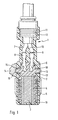
- Fig. 1 shows a partially sectioned view of the invention passive working according to the induction principle Sensor 1 represents.
- the sensor 1 essentially comprises one first housing part made of plastic or Coil body 2, in which a permanent magnet as electrical components 3, two pole pieces 4, a coil 5 and their contacts 6 are arranged, and a second, also made Plastic molded housing part 7.
- the contacts 6 are connected to electrical conductors 9 via crimp connections 8, which have an insulation 10 and in the further course through a grommet 11 overmolded by the second housing part 7 be passed to the sensor 1.
- the spout 11, the form-fitting has ribs 12 connected to the second housing part 7, serves to seal and position the cable 9, 10 in the second housing part 7.
- the first housing part 2 preferably comprises two in one piece positioning elements or thus formed according to the invention Pin 13.
- the positioning elements 13 extend in this embodiment in the radial direction based on the Center axis of the sensor 1 from the first housing part 2 to the outside and serve for spraying the second housing part 7 Positioning of the first housing part 2 and those located therein electrical components 3 - 6 in the injection mold 14.
- the positioning elements 13 are at least slightly from the outer contour 15 of the sensor 1.
- These stand out Sections 16 of the positioning elements 13 are positive or non-positive in corresponding recesses in the Form 14 inserted.
- the Positioning elements at least partially as a hole in the first Housing part 2 are formed. Not about either shown, insertable into this hole or pin-like pins The body is then fixed in place in the first housing part 2 in the extrusion mold 14. The positioning elements 13 then no longer have to be radially projecting, thereby advantageously on their possibly required Separation can be dispensed with.
- the Positioning elements 13 To prevent moisture from entering between the positioning elements 13 and the second housing part 7 are the Positioning elements 13 according to the invention with at least one, but preferably provided a plurality of melting elements 17, the with the second housing part 7 during its manufacture enter into a cohesive connection.
- the melting elements 17 are preferably as about the central axis of the Positioning elements 13 circumferential thin fins 18 educated.
- the fins 18 melt due to the contact temperature occurring here and the melting pressure of up to 400 bar partially and go to the cohesive and thus moisture-proof Connection with the second housing part 7.
- As a material for the first housing part 2 and thus also the fins 18 preferably become a thermoplastic Plastic used, the smaller or not a higher Has melting temperature than the second housing ice 7.
- the pole shoes 4 shown differently here completely from the second Housing part 7 are surrounded, so that at this point no moisture can penetrate into the sensor 1.
- the water entry at the bottom End of the first housing part 2 by further fins 19 avoided here based on the central axis of the sensor 1 are arranged radially circumferential and analogous to the Ribs 18 described above, in turn, a cohesive Enter into connection with the second housing part 7.
- FIG. 2 is in part sectional view of an active sensor according to the invention 20 shown.
- the active sensor 20 preferably comprises a combination of a magnetostatic or magnetoresistive sensitive element 21 and a bias magnet 22, which is magnetically shown here only schematically Encoder 23 is coupled.
- the contacts 25 of the IC 24 are preferably over Crimp contacts 26 connected to electrical conductors 27 which are each surrounded by insulation 28 and from the Sensor 20 are brought out.
- electrical conductors 27 which are each surrounded by insulation 28 and from the Sensor 20 are brought out.
- integral connections such as Soldering or welding, to manufacture the electrical Connection of the conductor 27 to the contacts 26 possible.
- a combination of a crimp connection is also conceivable here with such a cohesive connection.
- the sensor element 21 and the bias magnet 22 are in one embedded first housing part 29, which at the same time as a positioning element serves.
- the positioning element 29 instructs a positioning section 30 at its lower end the first housing part 29 during the spraying of the second Housing part 31 in an extrusion mold, not shown here is fixed against rotation and displacement.
- the section protruding beyond the outer contour 32 of the sensor 20 30 along along the completion of the sensor 30 the line 33 separated, for example cut off. This gives a sensor 20 with a very low one Size.
- the positioning element 29 has, as in the above, again as Melting ribs 34 formed elements that with the enter into a material connection in the second housing part 31 and so, as described above, the intrusion of moisture between the first and second housing parts Prevent 29, 31.
- the special shape of the first housing part 29 can whose wall thickness D can be made particularly small.
- the usable air gap L very large between the sensor element 21 and the encoder 23 held. This is a particularly noteworthy advantage because the installation space of the sensor, for example in Wheel bearings of an automobile that can be kept small.
- Fig. 3 shows a cross section of Fig. 2 along the Section line I - I.
- the outside of the first housing part 29 located electrical conductor 27 are about their insulation 28 of additional positioning elements 35 when spraying of the second housing part 31 held in the shape.
- additional positioning elements 35 can then be positioned using additional positioning elements be fixed in the extrusion mold.
- the positioning elements 35 again have melting elements 36, the Functionality and purpose has already been described above.
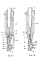
- 5a and 5b is another according to the invention active sensor 37 partly in section in a top and shown a side view.
- the structure of the electrical Components and their mode of operation with the sensor element 38, the bias magnet 39 and the IC package 40 is already in 2 and has been described here not be repeated.
- the contacts 41 of the IC 40 are again preferably over Crimp sleeves 42 connected to the electrical conductors 43.
- the crimp connection of these parts is advantageously carried out Way in a single operation.
- the crimp connection is in the embodiment of Fig. 5a (Pre-mold I) in the first Housing part 44 arranged so that possibly on the Cable 45 acting tensile forces not from the contacts 41 but received by the first housing part 44 via the crimp sleeves 42 become.
- Fig. 5a Pre-mold I
- Embodiment results in a further improvement, because in this way also when spraying of the second housing part 46 forces acting on the cable 45 can be received by the first housing part 44.
- the crimp connection according to FIG. 5b can also be done in second housing part 46 'may be arranged (pre-mold II). The Crimp connection can then be made after the injection molding of the first housing part 44 'are easier to manufacture because of the electronic Components 38-43 together with the first housing part 44 'are manageable.
- the first housing part 44, 44 ' is during the injection molding of the second Housing part 46, 46 'again via positioning elements 47, 47' fixed in an extrusion mold, not shown, the protruding sections 48, 48 'of the positioning elements 47, 47 'after the completion of the sensor 37.
- the seal between the first and second housing parts 44, 44 'and 46, 46' is again carried out by material fit with the second housing part 46, 46 'melt fins 49, which are integrally connected to the first housing part 44, 44 ' are.
- the carrier sheet one in particular designed as a chip sensor element 38 with radial projecting portions 53 provided, preferably are ear-shaped.
- a support 53 also known as lead frame support, can the component 38 during the injection molding process of the second Housing part 46, 46 'in the first housing part 44, 44' and / or the injection mold, not shown, are fixed. It will such a blurring of the sensor element 38 during the extrusion coating effectively prevents what accurate positioning of the electrical component 38 in the first housing part 44. In this way, in particular, the position of the reading point of the sensor element 38 in the sensor 37 is exactly determined become.
- FIGS. 6 and 7 show a further embodiment of a active sensor 54 according to the invention.
- the sensor 54 again has a first and second housing part 55, 56 on. Positioning elements are in one piece with the first housing part 55 57 connected, the seal against the Environment again preferably takes place via fins 58. Electrical components are also in the first housing part 55 arranged like a sensor element 59 and an IC package 60.
- the housing 60 has contacts 61, which here are crimp sleeves 62 are electrically conductively connected to conductors 63. As already mentioned, this connection is also cohesive or as a combination of a material connection with a crimp connection.
- the conductors 63 are provided with insulation and are connected via a cable 64 passed from the sensor 54.
- the sensor element 59 has radially projecting sections 65 on that as a support for fixing the sensor element 59 and thus defining an exact reading point in the sensor 54 serve.
- the sections 65 can be groove-like openings of the first housing part 55 be inserted or inserted, so that the encapsulation of the electrical components 59 - 63 omitted here and by Insert can be replaced.
- the crimp contacts 62 are in this embodiment with a Holding element 66 connected.
- This holding element 66 is anchored in the spraying of the first housing part 55 in this and can thus advantageously on the crimp connection absorb acting tensile forces and on the first housing part 55 forward.
Landscapes
- Engineering & Computer Science (AREA)
- Mechanical Engineering (AREA)
- Physics & Mathematics (AREA)
- General Physics & Mathematics (AREA)
- Manufacturing & Machinery (AREA)
- Injection Moulding Of Plastics Or The Like (AREA)
- Transmission And Conversion Of Sensor Element Output (AREA)
- Materials For Medical Uses (AREA)
- Diaphragms For Electromechanical Transducers (AREA)
- Lining Or Joining Of Plastics Or The Like (AREA)
- Moulds For Moulding Plastics Or The Like (AREA)
Description
- Fig. 1
- eine teilweise geschnittene Ansicht einen erfindungsgemäßen passiven Kunststoffsensors,
- Fig. 2
- eine erste Ausführungsform eines aktiven Kunststoffsensors in teilweise geschnittener Darstellung,
- Fig. 3
- einen Querschnitt der Ausführungsform gemäß Fig. 2 entlang der Linie I - I,
- Fig. 4
- eine weitere Ausführungsform eines erfindungsgemäßen aktiven Sensors in teilweise geschnittener Ansicht,
- Fig.5a
- eine geschnittene Seitenansicht der in Fig. 4 dargestellten Ausführungsform,
- Fig.5b
- eine geschnittene Seitenansicht einer zu Fig. 5a alternativen Ausführungsform,
- Fig. 6
- eine weitere Ausführungsform eines erfindungsgemäßen aktiven Sensors in geschnittener Seitenansicht, und
- Fig. 7
- eine Schnittansicht der in Fig. 6 dargestellten Ausführungsform.
- 1
- passiver Sensor
- 2
- erstes Gehäuseteil
- 3
- Permanentmagnet
- 4
- Polschuhe
- 5
- Spule
- 6
- Kontakte
- 7
- zweiter Gehäuseteil
- 8
- Crimpverbindungen
- 9
- elektrische Leiter
- 10
- Isolation
- 11
- Tülle
- 12
- Rippen
- 13
- Positionierelemente
- 14
- Umspritzform
- 15
- Außenkontur des Sensors
- 16
- Positionierabschnitt
- 17
- Schmelzelemente
- 18
- Schmelzrippen
- 19
- Schmelzrippen
- 20
- aktiver Sensor
- 21
- Sensorelement
- 22
- Vorspannmagnet
- 23
- Encoder
- 24
- IC-Gehäuse
- 25
- Kontakte
- 26
- Crimphülsen
- 27
- elektrische Leiter
- 28
- Isolierung
- 29
- erster Gehäuseteil bzw. Positionierelement
- 30
- Positionierabschnitt
- 31
- zweiter Gehäuseteil
- 32
- Außenkontur
- 33
- Abtrennlinie
- 34
- Schmelzrippen
- 35
- Positionierelemente
- 36
- Schmelzrippen
- 37
- aktiver Sensor
- 38
- Sensorelement
- 39
- Vorspannmagnet
- 40
- IC-Gehäuse
- 41
- Kontakte
- 42
- Crimphülsen
- 43
- elektrische Leiter
- 44, 44'
- erster Gehäuseteil
- 45
- Kabel
- 46, 46'
- zweiter Gehäuseteil
- 47, 47'
- Positionierelemente
- 48, 48'
- Positionierabschnitte
- 49
- Schmelzrippen
- 50
- Abstützabdruck
- 51
- Abstützabdruck
- 52
- Abstützabdruck
- 53
- (Leadframe-) Abstützung
- 54
- aktiver Sensor
- 55
- erster Gehäuseteil
- 56
- zweiter Gehäuseteil
- 57
- Positionierelemente
- 58
- Schmelzelemente
- 59
- Sensorelement
- 60
- IC-Gehäuse
- 61
- Kontakte
- 62
- Crimphülsen
- 63
- elektrische Leiter
- 64
- Kabel
- 65
- (Leadframe-) Abstützung
- 66
- Halteelement
- D
- Wanddicke
- L
- nutzbarer Luftspalt
Claims (30)
- Sensor zur Erfassung von Ortsverschiebungen, Bewegungsgeschwindigkeiten oder Drehzahlen eines Encoders, mit einem elektrische Bauteile (3 - 6, 8 - 10, 21 - 28, 38 - 43, 45, 59 - 63) aufnehmenden Gehäuse mit einem ersten Gehäuseteil (2, 29, 44, 44', 55) aus Kunststoff, welches von einem zweiten, in einem Spritzgießvorgang ebenfalls aus Kunststoff erzeugten Gehäuseteil (7, 31, 46, 46', 56) zumindest teilweise umhüllt ist, dadurch gekennzeichnet, daß der erste Gehäuseteil (2, 29, 44, 44', 55) wenigstens ein einstückig damit verbundenes Positionierelement (13, 29, 47, 47', 57) umfaßt, das mit dem zweiten Gehäuseteil (7, 31, 46, 46', 56) stoffschlüssig verbunden ist.
- Sensor nach Anspruch 1, dadurch gekennzeichnet, daß das Positionierelement (13, 29, 47, 47', 57) und/oder der erste Gehäuseteil (2, 29, 44, 44', 55) zumindest ein integriertes Schmelzelement (17, 19, 34, 49, 58) umfassen.
- Sensor nach Anspruch 2, dadurch gekennzeichnet, daß die Schmelzelemente als dünne Rippen (18, 19, 34, 49, 58) ausgebildet sind.
- Sensor nach Anspruch 2 oder 3, dadurch gekennzeichnet, daß die Schmelzelemente (18, 19, 34, 49, 58) aus thermoplastischem Material bestehen, das einen kleineren oder höchstens gleichen Schmelzpunkt wie das Material des zweiten Gehäuseteils (7, 31, 46, 46', 56) aufweist.
- Sensor nach einem der vorhergehenden Ansprüche, dadurch gekennzeichnet, daß außerhalb des ersten Gehäuseteils (29) angeordnete elektrische Bauteile (27, 28) mit wenigstens einem zusätzlichen Positionierelement (35) versehen sind, das mit dem zweiten Gehäuseteil (31) stoffschlüssig verbunden ist.
- Sensor nach einem der vorhergehenden Ansprüche, dadurch gekennzeichnet, daß wenigstens ein Abschnitt eines Positionierelementes (13, 29, 35, 47, 47',57) im ersten Gehäuseteil (2, 29, 44, 44', 55) als Bohrung ausgebildet ist.
- Sensor nach Anspruch 6, dadurch gekennzeichnet, daß die Bohrung zur Aufnahme eines Siftes oder stiftähnlichen Körpers geeignet ist.
- Sensor nach einem der vorhergehenden Ansprüche, dadurch gekennzeichnet, daß sich die Positionierelemente (13, 35, 47, 47', 57) bezogen auf die Mittelachse des Sensors (1, 37) radial nach außen erstrecken.
- Sensor nach Anspruch 6 oder 8, dadurch gekennzeichnet, daß die Schmelzelemente (18, 36, 49, 58) radial umlaufend um die Mittelachse der Positionierelemente (13, 35, 47, 57) angeordnet sind.
- Sensor nach einem der Ansprüche 1 - 4, dadurch gekennzeichnet, daß die Schmelzelemente (19) bezogen auf die Mittelachse des Sensors (1) radial umlaufend an zumindest einem Ende des ersten Gehäuseteils (2) angeordnet sind.
- Sensor nach einem der Ansprüche 1 - 4, dadurch gekennzeichnet, daß die Positionierelemente (13, 29, 47, 47', 57) zumindest geringfügig über die Außenkontur (15, 32) des Sensors (1, 20, 37, 54) hinausragen.
- Sensor nach Anspruch 11, dadurch gekennzeichnet, daß die über die Außenkontur (15, 32) des Sensors (1, 20, 37, 54) hinausragenden Abschnitte (16, 30, 48, 48') der Positionierelemente (13, 29, 47, 47', 57) leicht entfernbar sind.
- Sensor nach einem der Ansprüche 1 - 4, dadurch gekennzeichnet, daß die elektrisch leitende Verbindung der Kontakte (6, 25, 41, 61) der elektrischen Bauteile (5, 24, 40, 60) mit den elektrischen Leitern (9, 27, 43, 63) eine stoffschlüssige Verbindung, wie beispielsweise Löten oder Schweißen, ist.
- Sensor nach einem der Ansprüche 1 - 4, dadurch gekennzeichnet, daß zur elektrisch leitenden Verbindung der Kontakte (6, 25, 41, 61) der elektrischen Bauteile (5, 24, 40, 60) mit den elektrischen Leitern (9, 27, 43, 63) Crimpverbindungen (8, 26, 42, 62) vorgesehen sind.
- Sensor nach einem der Ansprüche 13 oder 14, dadurch gekennzeichnet, daß die elektrisch leitende Verbindung eine Kombination einer stoffschlüssigen Verbindung und einer kraftschlüssigen Verbindung ist, wobei als kraftschlüssige Verbindung vorzugsweise Crimpverbindungen (8, 26, 42, 62) vorgesehen sind.
- Sensor nach Anspruch 14 oder 15, dadurch gekennzeichnet, daß die Crimpverbindungen (42) im ersten Gehäuseteil (44) angeordnet sind.
- Sensor nach Anspruch 14 oder 15, dadurch gekennzeichnet, daß die Crimpverbindungen (42, 62) im zweiten Gehäuseteil (44', 56) angeordnet sind.
- Sensor nach einem der vorhergehenden Ansprüche, dadurch gekennzeichnet, daß die elektrischen Bauteile (38, 59) zumindest teilweise radial nach außen vorspringende Abschnitte (53, 65) aufweisen.
- Sensor nach Anspruch 18, dadurch gekennzeichnet, daß zumindest der erste Gehäuseteil (55) Öffnungen, insbesondere Nuten, zur Aufnahme der nach außen vorspringende Abschnitte (65) der elektrischen Bauteile (59) aufweist.
- Verfahren zur Herstellung eines Sensors zur Erfassung von Ortsverschiebungen, Bewegungsgeschwindigkeiten oder Drehzahlen eines Encoders, mit einem elektrische Bauteile (3 - 6, 8 - 10, 21 - 28, 38 - 43, 45, 59 - 63) aufnehmenden Gehäuse, das einen ersten (2, 29, 44, 44', 55) und zweiten (7, 31, 46, 46', 56) Gehäuseteil aus Kunststoff aufweist, mit den Verfahrensschrittena) Umspritzen und/oder Einlegen zumindest eines Teils der elektrischen Bauteile (3 - 6, 21, 22, 38 - 43, 59 - 63) mit/in einem/einen ersten Gehäuseteil (2, 29, 44, 44', 55),b) Fixierung des ersten Gehäuseteils (2, 29, 44, 44', 55) in einer Umspritzform (14) mittels zumindest eines einstückig mit dem ersten Gehäuseteil (2, 29, 44, 44', 55) verbundenen Positionierelementes (13, 29, 47, 47', 57),c) Umspritzen des ersten Gehäuseteils (2, 29, 44, 44', 55) mit dem zweiten Gehäuseteil (7, 31, 46, 46', 56) undd) Herstellung einer stoffschlüssigen Verbindung zwischen den Positionierelementen (13, 29, 35, 47, 47', 57) und dem zweiten Gehäuseteil (7, 31, 46, 46', 56).
- Verfahren nach Anspruch 20, dadurch gekennzeichnet, daß außerhalb des ersten Gehäuseteils (29) angeordnete elektrische Bauteile (27, 28) vor dem Spritzen des zweiten Gehäuseteils (31) mittels zumindest eines weiteren Positionierelementes (35) in der Umspritzform fixiert werden.
- Verfahren nach Anspruch 20, dadurch gekennzeichnet, daß die Fixierung des ersten Gehäuseteils(2, 29, 44, 44', 55) in der Umspritzform (14) über zumindest einen Stift erfolgt, der in einer Bohrung eines Positionierelementes (13, 29, 35, 47, 47', 57) fixiert wird.
- Verfahren nach Anspruch 20, dadurch gekennzeichnet, daß nach dem Spritzen des zweiten Gehäuseteils (7, 31, 46, 46', 56) die über die Außenkontur (15, 32) des Sensors (1, 20, 37, 54) hinausragenden Abschnitte (16, 30, 48, 48') der Positionierelemente (13, 29, 47, 47', 57) abgetrennt werden.
- Verfahren nach Anspruch 20, dadurch gekennzeichnet, daß die Kontakte (6, 25, 41, 61) der elektrischen Bauteile (5, 24, 40, 60) und die elektrischen Leiter (9, 27, 43, 63) mittels einer stoffschlüssigen Verbindung, wie beispielsweise Löten oder Schweißen, elektrisch leitend verbunden werden.
- Verfahren nach Anspruch 20, dadurch gekennzeichnet, daß die Kontakte (6, 25, 41, 61) der elektrischen Bauteile (5, 24, 40, 60) und die elektrischen Leiter (9, 27, 43, 63) mittels Crimpverbindungen (8, 26, 42, 62), vorzugsweise in einem einzigen Schritt, elektrisch leitend verbunden werden.
- Verfahren nach einem der Ansprüche 24 oder 25, dadurch gekennzeichnet, daß die elektrisch leitende Verbindung durch eine Kombination einer stoffschlüssigen Verbindung mit einer kraftschlüssigen Verbindung erfolgt, wobei die kraftschlüssige Verbindung vorzugsweise mittels Crimpverbindungen (8, 26, 42, 62) erfolgt.
- Verfahren nach einem der Ansprüche 24 bis 26, dadurch gekennzeichnet, daß die Herstellung der elektrisch leitenden Verbindung vor dem Umspritzen der elektrischen Bauteile (38 - 43) mit dem ersten Gehäuseteil (44) erfolgt.
- Verfahren nach einem der Ansprüche 24 bis 26, dadurch gekennzeichnet, daß die Herstellung der elektrisch leitenden Verbindung nach dem Umspritzen der elektrischen Bauteile (38 - 40) mit dem ersten Gehäuseteil (44') erfolgt.
- Verfahren nach Anspruch 20, dadurch gekennzeichnet, daß die elektrischen Bauteile (38, 59) vor dem Spritzen des zweiten Gehäuseteils (46, 56) zumindest teilweise über radial vorspringende Abschnitte (53, 65) im ersten Gehäuseteil (44, 55) und/oder der Umspritzform fixiert werden.
- Verfahren nach Anspruch 20, dadurch gekennzeichnet, daß die elektrischen Bauteile (59) vor dem Spritzen des zweiten Gehäuseteils (56) zumindest teilweise über radial vorspringende Abschnitte (65) in Öffnungen, insbesondere Nuten, des ersten Gehäuseteils (55) fixiert werden.
Applications Claiming Priority (3)
| Application Number | Priority Date | Filing Date | Title |
|---|---|---|---|
| DE19612765 | 1996-03-29 | ||
| DE19612765A DE19612765A1 (de) | 1996-03-29 | 1996-03-29 | Kunststoffsensor und Verfahren zu dessen Herstellung |
| PCT/EP1997/001456 WO1997036729A1 (de) | 1996-03-29 | 1997-03-21 | Kunststoffsensor und verfahren zu dessen herstellung |
Publications (2)
| Publication Number | Publication Date |
|---|---|
| EP0889774A1 EP0889774A1 (de) | 1999-01-13 |
| EP0889774B1 true EP0889774B1 (de) | 2002-01-09 |
Family
ID=7789998
Family Applications (1)
| Application Number | Title | Priority Date | Filing Date |
|---|---|---|---|
| EP97915413A Expired - Lifetime EP0889774B1 (de) | 1996-03-29 | 1997-03-21 | Kunststoffsensor und verfahren zu dessen herstellung |
Country Status (13)
| Country | Link |
|---|---|
| US (1) | US6334361B1 (de) |
| EP (1) | EP0889774B1 (de) |
| JP (1) | JP2000508068A (de) |
| CN (1) | CN1074976C (de) |
| AT (1) | ATE211676T1 (de) |
| CZ (1) | CZ303898A3 (de) |
| DE (2) | DE19612765A1 (de) |
| ES (1) | ES2166531T3 (de) |
| HU (1) | HU223248B1 (de) |
| PL (1) | PL182626B1 (de) |
| PT (1) | PT889774E (de) |
| SK (1) | SK131598A3 (de) |
| WO (1) | WO1997036729A1 (de) |
Cited By (2)
| Publication number | Priority date | Publication date | Assignee | Title |
|---|---|---|---|---|
| DE102005054025B4 (de) * | 2004-11-10 | 2014-12-04 | Kendrion (Villingen) Gmbh | Verfahren zur mediendichten Ummantelung eines als Spulensystem ausgeführten Betätigungsmagneten sowie mediendichter Betätigungsmagnet in Form eines Spulensystems |
| DE102014212720A1 (de) | 2013-07-01 | 2015-01-08 | Continental Teves Ag & Co. Ohg | Sensor mit abdichtender Beschichtung |
Families Citing this family (64)
| Publication number | Priority date | Publication date | Assignee | Title |
|---|---|---|---|---|
| JP3208371B2 (ja) | 1997-12-18 | 2001-09-10 | 株式会社ホンダロック | センサ装置 |
| DE19857880B4 (de) * | 1997-12-18 | 2008-07-31 | Honda Lock Mfg. Co., Ltd. | Sensor |
| US20020058122A1 (en) * | 2000-11-06 | 2002-05-16 | Tsuyoshi Arai | Insert molded product |
| DE10155537B4 (de) * | 2001-01-05 | 2016-02-11 | Continental Teves Ag & Co. Ohg | Verfahren und Spritzgussform zur Herstellung von Kraftfahrzeugsensoren |
| DE10155538B4 (de) * | 2001-01-09 | 2017-02-09 | Continental Teves Ag & Co. Ohg | Verfahren zur Herstellung eines Gehäuses oder von Gehäuseelementen nach dem Spritzgußverfahren |
| WO2002095335A1 (de) * | 2001-05-23 | 2002-11-28 | Continental Teves Ag & Co. Ohg | Elektronischer sensor mit elektronischen sensorbauelementen und verfahren zu dessen herstellung |
| JP3866531B2 (ja) * | 2001-06-01 | 2007-01-10 | 株式会社ホンダロック | センサ装置 |
| JP3714204B2 (ja) * | 2001-06-29 | 2005-11-09 | 株式会社デンソー | 回転検出装置及びその製造方法 |
| JP3711951B2 (ja) * | 2002-02-28 | 2005-11-02 | 株式会社デンソー | センサ構造及びセンサの製造方法 |
| FR2837926B1 (fr) * | 2002-03-27 | 2004-05-28 | Siemens Vdo Automotive | Procede de fabrication d'un capteur de vitesse d'une roue et capteur correspondant |
| DE10225019A1 (de) * | 2002-06-06 | 2003-12-18 | Hella Kg Hueck & Co | Läufer für Induktivsensor |
| JP4281537B2 (ja) * | 2003-12-04 | 2009-06-17 | 株式会社デンソー | 回転検出センサ装置 |
| FR2864700A1 (fr) * | 2003-12-31 | 2005-07-01 | Siemens Vdo Automotive | Procede d'enrobage d'une unite electronique d'un capteur et capteur correspondant |
| JP2005227156A (ja) * | 2004-02-13 | 2005-08-25 | Honda Lock Mfg Co Ltd | センサ装置 |
| ITMI20050334A1 (it) * | 2004-03-11 | 2005-09-12 | Leuze Electronic Gmbh Co Kg | Sensore ottico per il rilevamento di oggetti in una zona di monitoraggio |
| DE102004054059B4 (de) * | 2004-11-05 | 2019-05-23 | Continental Automotive Gmbh | Sensoranordnung und Verfahren zum Herstellen einer Sensoranordnung |
| DE102005012709A1 (de) * | 2005-03-22 | 2006-09-28 | Robert Bosch Gmbh | Magnetfeldsensor |
| JP4514682B2 (ja) * | 2005-09-30 | 2010-07-28 | 住電エレクトロニクス株式会社 | 回転検出センサ |
| JP4514702B2 (ja) * | 2005-12-21 | 2010-07-28 | 住電エレクトロニクス株式会社 | 回転検出センサ |
| JP4514701B2 (ja) * | 2005-12-21 | 2010-07-28 | 住電エレクトロニクス株式会社 | 回転検出センサ |
| DE102006049250A1 (de) * | 2006-10-19 | 2008-04-30 | Robert Bosch Gmbh | Sensorvorrichtung |
| US7655319B2 (en) * | 2007-02-02 | 2010-02-02 | Continental Automotive Systems Us, Inc. | Plastic positioning pin for overmolded product |
| JP4851963B2 (ja) * | 2007-03-05 | 2012-01-11 | 本田技研工業株式会社 | 回転センサの製造方法 |
| DE102008008336B4 (de) * | 2007-03-19 | 2025-03-13 | Vitesco Technologies Germany Gmbh | Verfahren zur Positionsbestimmung und zur Positionierung eines abgedeckten Sensorelements einer Sensoranordnung sowie Sensoranordnung mit einem entsprechend positionierten Sensorelement |
| JP4851973B2 (ja) * | 2007-03-22 | 2012-01-11 | 本田技研工業株式会社 | 回転センサ及びその製造方法 |
| DE102007056544A1 (de) * | 2007-11-23 | 2009-05-28 | Robert Bosch Gmbh | Sensoranordnung zur Bestimmung eines Tankfüllstands und Verfahren zur Herstellung hierzu |
| US8497468B2 (en) * | 2007-12-20 | 2013-07-30 | Heidenhain Corporation | Encoder having an overmolded cover, encoder system with an encoder having an overmolded cover, and method for manufacturing an encoder having an overmolded cover |
| DE102008005315A1 (de) * | 2008-01-21 | 2009-07-23 | Robert Bosch Gmbh | Verfahren und Vorrichtung zur Herstellung eines Magnetfeldsensors |
| DE102008029192A1 (de) * | 2008-03-13 | 2009-09-24 | Epcos Ag | Fühler zum Erfassen einer physikalischen Größe und Verfahren zur Herstellung des Fühlers |
| DE102008064047A1 (de) | 2008-10-02 | 2010-04-08 | Continental Teves Ag & Co. Ohg | Sensorelement und Trägerelement zur Herstellung eines Sensors |
| DE102008064046A1 (de) * | 2008-10-02 | 2010-04-08 | Continental Teves Ag & Co. Ohg | Verfahren zur Herstellung eines Geschwindigkeits-Sensorelementes |
| WO2011007385A1 (ja) * | 2009-07-14 | 2011-01-20 | 三菱電機株式会社 | 車両状態検出装置および製造方法 |
| DE102009028963A1 (de) * | 2009-08-28 | 2011-03-03 | Robert Bosch Gmbh | Anschlussanordnung für eine Sensoranordnung und Sensoranordnung |
| JP5930309B2 (ja) * | 2012-01-27 | 2016-06-08 | 株式会社デンソー | 回転検出装置およびその製造方法 |
| CN103226152B (zh) * | 2012-01-27 | 2015-04-29 | 株式会社电装 | 旋转检测装置及其制造方法 |
| DE102013219018A1 (de) * | 2012-12-20 | 2014-06-26 | Continental Teves Ag & Co. Ohg | Winkelsensors |
| DE102012224075A1 (de) * | 2012-12-20 | 2014-06-26 | Continental Teves Ag & Co. Ohg | Sensor zum Erfassen einer Position eines Geberelements |
| DE102013217888B4 (de) * | 2012-12-20 | 2024-07-04 | Continental Automotive Technologies GmbH | Elektronische Vorrichtung und Verfahren zur Herstellung einer elektronischen Vorrichtung |
| EP2871447B1 (de) * | 2013-11-08 | 2017-03-01 | Nexans | Anordnung zur überwachung eines sich um seine achse drehenden bauteils mit einem drehzahlsensor und einem temperatursensor |
| DE102014208425A1 (de) * | 2013-11-28 | 2015-05-28 | Continental Teves Ag & Co. Ohg | Verfahren zum Herstellen eines Sensors |
| US9664705B2 (en) | 2014-02-19 | 2017-05-30 | Sensata Technologies, Inc. | Speed sensor |
| JP6344043B2 (ja) * | 2014-05-09 | 2018-06-20 | アイシン精機株式会社 | センサ |
| DE102014216772B4 (de) | 2014-08-22 | 2022-09-29 | Zf Friedrichshafen Ag | Anordnung zur lagegenauen Positionierung eines elektronischen Bauteileträgers |
| DE102015224255A1 (de) * | 2015-12-03 | 2017-06-08 | Continental Teves Ag & Co. Ohg | Raddrehzahlsensorsystem |
| JP6153146B1 (ja) | 2016-04-14 | 2017-06-28 | 三菱電機株式会社 | 回転センサ |
| DE102016207664A1 (de) * | 2016-05-03 | 2017-11-09 | Continental Teves Ag & Co. Ohg | Sensorelement für ein kraftfahrzeug |
| FR3055737B1 (fr) * | 2016-09-08 | 2018-11-30 | Continental Automotive France | Procede de fabrication sur une plaque de maintien metallique d'au moins un module electronique incluant au moins un test electrique |
| US11448531B2 (en) | 2016-09-26 | 2022-09-20 | Sumitomo Wiring Systems, Ltd. | Sensor component, sensor, and method for manufacturing sensor |
| FR3059202B1 (fr) * | 2016-11-18 | 2019-08-16 | Continental Automotive France | Procede de fabrication sur une plaque de maintien d'un module electronique avec des formes de positionnement depassant du surmoulage final |
| DE102016223816A1 (de) * | 2016-11-30 | 2018-05-30 | Robert Bosch Gmbh | Verfahren zum Herstellen eines elektrischen oder mechanischen Elements |
| JP6891776B2 (ja) | 2017-11-28 | 2021-06-18 | 住友電装株式会社 | インナ部品及び樹脂成形品 |
| JP6928875B2 (ja) * | 2017-12-06 | 2021-09-01 | 住友電装株式会社 | 樹脂成形品 |
| JP6939583B2 (ja) * | 2018-01-11 | 2021-09-22 | 日立金属株式会社 | 樹脂成形体付きケーブルの製造方法 |
| JP6939584B2 (ja) * | 2018-01-11 | 2021-09-22 | 日立金属株式会社 | 樹脂成形体付きケーブルの製造方法 |
| DE102018003133A1 (de) * | 2018-04-17 | 2019-10-17 | Infineon Technologies Ag | Sensorvorrichtung, sensormodul, spritzgusswerkzeug und verfahren zur herstellung eines sensormoduls |
| DE102018132709A1 (de) * | 2018-12-18 | 2020-06-18 | Knorr-Bremse Systeme für Nutzfahrzeuge GmbH | Induktiver Drehzahlsensor und ein Verfahren zu dessen Herstellung |
| DE102018132694A1 (de) | 2018-12-18 | 2020-06-18 | Knorr-Bremse Systeme für Nutzfahrzeuge GmbH | Spulenkörper, Induktiver Drehzahlsensor und Verfahren zu deren Herstellung |
| DE102019200768A1 (de) | 2019-01-23 | 2020-07-23 | Zf Friedrichshafen Ag | Verfahren und Werkzeug zum Umspritzen eines Elektronikmoduls und umspritztes Elektronikmodul |
| DE102019115397A1 (de) * | 2019-06-06 | 2020-12-10 | Knorr-Bremse Systeme für Nutzfahrzeuge GmbH | Raddrehzahlsensor für ein Nutzfahrzeug |
| DE102019210210A1 (de) * | 2019-07-10 | 2021-01-14 | Continental Teves Ag & Co. Ohg | Variativ herstellbare Warnvorrichtung zur Überwachung eines Behälterfüllstandes, Spritzgusswerkzeug und Herstellverfahren |
| DE102019123991A1 (de) | 2019-09-06 | 2021-03-11 | Knorr-Bremse Systeme für Nutzfahrzeuge GmbH | Fahrzeugdrehzahlsensor und Verfahren zur dessen Herstellung |
| JP7404956B2 (ja) * | 2020-03-23 | 2023-12-26 | 住友電装株式会社 | 複合成形部品の製造方法 |
| DE102021102721A1 (de) | 2021-02-05 | 2022-08-11 | Knorr-Bremse Systeme für Nutzfahrzeuge GmbH | Vormontagebaugruppe für einen Raddrehzahlsensor sowie Raddrehzahlsensor für ein Nutzfahrzeug und Verfahren zu dessen Herstellung |
| DE102024124766A1 (de) * | 2024-08-29 | 2026-03-05 | Seamless Energy Technologies Gesellschaft mbH | Verfahren und Vorrichtung zum Herstellen einer induktiven Ladeeinheit, Träger sowie induktive Ladeeinheit |
Family Cites Families (22)
| Publication number | Priority date | Publication date | Assignee | Title |
|---|---|---|---|---|
| DE2410630C3 (de) * | 1974-03-06 | 1978-08-31 | Robert Bosch Gmbh, 7000 Stuttgart | Impulsdrehzahlgeber |
| GB2007581B (en) * | 1977-09-05 | 1982-02-17 | Brooker B F | Ball |
| DE3346159A1 (de) * | 1983-12-21 | 1985-07-04 | Vdo Adolf Schindling Ag, 6000 Frankfurt | Verfahren zur herstellung eines induktionsgebers |
| DE3400870A1 (de) * | 1984-01-12 | 1985-07-25 | Vdo Adolf Schindling Ag, 6000 Frankfurt | Induktivgeber |
| FR2576245B1 (fr) * | 1985-01-23 | 1987-04-30 | Jaeger | Procede d'enrobage d'un capteur allonge, dispositif de moulage pour la mise en oeuvre du procede, capteur obtenu et armature intervenant dans la fabrication du capteur |
| JPH0757500B2 (ja) * | 1987-10-31 | 1995-06-21 | 日精エー・エス・ビー機械株式会社 | プリフオーム口部成形金型へのピースインサート方法 |
| FR2646009B1 (fr) * | 1989-04-18 | 1993-01-22 | Siemens Bendix Automotive Elec | Capteur inductif a reluctance variable |
| DE3930702A1 (de) * | 1989-09-14 | 1991-03-28 | Bosch Gmbh Robert | Sensor, insbesondere drehzahlfuehler |
| JPH049721A (ja) * | 1990-04-27 | 1992-01-14 | Mitsubishi Electric Corp | 振動検出器 |
| JPH04252739A (ja) * | 1991-01-30 | 1992-09-08 | Yazaki Corp | プラスチック製メータケース及びその製造方法 |
| US5184064A (en) * | 1991-03-25 | 1993-02-02 | Stewart & Stevenson Services, Inc. | Encapsulated meter with optical programmer |
| DE4228888A1 (de) * | 1992-08-29 | 1994-03-03 | Bosch Gmbh Robert | Induktiver Sensor |
| DE9303412U1 (de) * | 1993-03-09 | 1993-05-06 | Heinrich Baumgarten KG, Spezialfabrik für Beschlagteile, 57290 Neunkirchen | Abdeckgehäuse |
| DE4323084A1 (de) * | 1993-07-10 | 1995-01-12 | Vdo Schindling | Induktiver Drehzahlgeber und Verfahren zu seiner Herstellung |
| DE4324557A1 (de) * | 1993-07-22 | 1995-02-23 | Vdo Schindling | Verfahren zur Herstellung eines Induktivgebers und nach diesem Verfahren hergestellter Induktivgeber |
| US5633062A (en) * | 1993-09-01 | 1997-05-27 | Sumitomo Electric Industries, Ltd. | Method of manufacturing rotation sensor and structure of rotation sensor |
| DE4422739A1 (de) * | 1994-06-29 | 1996-01-04 | Teves Gmbh Alfred | Verfahren zum dünnwandigen Umgießen einer zu der umgossenen Wand genau ausgerichteten Elektronikschaltung und Elektronikschaltung hierzu |
| DE4444714C2 (de) * | 1994-12-15 | 1998-07-02 | Mannesmann Vdo Ag | Verfahren zur Herstellung eines induktiven Drehzahlgebers |
| US5629618A (en) * | 1994-12-27 | 1997-05-13 | Ssi Technologies, Inc. | Housing for a wheel speed sensor |
| DE19504608C2 (de) * | 1995-02-11 | 2002-03-21 | Balluff Gebhard Feinmech | Positionssensor und Verfahren zur Herstellung desselben |
| US5685884A (en) * | 1995-10-13 | 1997-11-11 | Bently Nevada Corporation | Method of making a transducer |
| DE19544815C1 (de) * | 1995-12-01 | 1997-04-10 | Balluff Gebhard Gmbh & Co | Sensor und Verfahren zu seiner Herstellung |
-
1996
- 1996-03-29 DE DE19612765A patent/DE19612765A1/de not_active Withdrawn
-
1997
- 1997-03-21 PT PT97915413T patent/PT889774E/pt unknown
- 1997-03-21 DE DE59705978T patent/DE59705978D1/de not_active Expired - Lifetime
- 1997-03-21 HU HU9903542A patent/HU223248B1/hu active IP Right Grant
- 1997-03-21 JP JP9534885A patent/JP2000508068A/ja active Pending
- 1997-03-21 CN CN97193531A patent/CN1074976C/zh not_active Expired - Lifetime
- 1997-03-21 EP EP97915413A patent/EP0889774B1/de not_active Expired - Lifetime
- 1997-03-21 US US09/155,456 patent/US6334361B1/en not_active Expired - Lifetime
- 1997-03-21 SK SK1315-98A patent/SK131598A3/sk unknown
- 1997-03-21 CZ CZ983038A patent/CZ303898A3/cs unknown
- 1997-03-21 ES ES97915413T patent/ES2166531T3/es not_active Expired - Lifetime
- 1997-03-21 PL PL97329124A patent/PL182626B1/pl not_active IP Right Cessation
- 1997-03-21 WO PCT/EP1997/001456 patent/WO1997036729A1/de not_active Ceased
- 1997-03-21 AT AT97915413T patent/ATE211676T1/de not_active IP Right Cessation
Cited By (3)
| Publication number | Priority date | Publication date | Assignee | Title |
|---|---|---|---|---|
| DE102005054025B4 (de) * | 2004-11-10 | 2014-12-04 | Kendrion (Villingen) Gmbh | Verfahren zur mediendichten Ummantelung eines als Spulensystem ausgeführten Betätigungsmagneten sowie mediendichter Betätigungsmagnet in Form eines Spulensystems |
| DE102014212720A1 (de) | 2013-07-01 | 2015-01-08 | Continental Teves Ag & Co. Ohg | Sensor mit abdichtender Beschichtung |
| WO2015000905A1 (de) | 2013-07-01 | 2015-01-08 | Continental Teves Ag & Co. Ohg | Sensor mit abdichtender beschichtung |
Also Published As
| Publication number | Publication date |
|---|---|
| WO1997036729A1 (de) | 1997-10-09 |
| CN1215363A (zh) | 1999-04-28 |
| ES2166531T3 (es) | 2002-04-16 |
| ATE211676T1 (de) | 2002-01-15 |
| US6334361B1 (en) | 2002-01-01 |
| CN1074976C (zh) | 2001-11-21 |
| DE19612765A1 (de) | 1997-11-13 |
| PL329124A1 (en) | 1999-03-15 |
| JP2000508068A (ja) | 2000-06-27 |
| SK131598A3 (en) | 1999-04-13 |
| HUP9903542A3 (en) | 2000-12-28 |
| HU223248B1 (hu) | 2004-04-28 |
| PL182626B1 (pl) | 2002-02-28 |
| PT889774E (pt) | 2002-06-28 |
| CZ303898A3 (cs) | 1999-04-14 |
| EP0889774A1 (de) | 1999-01-13 |
| DE59705978D1 (de) | 2002-02-14 |
| HUP9903542A2 (hu) | 2000-02-28 |
Similar Documents
| Publication | Publication Date | Title |
|---|---|---|
| EP0889774A1 (de) | Kunststoffsensor und verfahren zu dessen herstellung | |
| EP2235551B1 (de) | Magnetfeldsensor | |
| DE3889752T2 (de) | Sensor zur Feststellung von einer Änderung im magnetischen Feld. | |
| DE10320145B4 (de) | Magnetische Detektionsvorrichtung | |
| EP3074730B1 (de) | Sensorherstellung durch halten des zwischenspritzlings | |
| EP0491703B1 (de) | Sensor, insbesondere drehzahlfühler | |
| EP1634687B1 (de) | Verfahren zur Herstellung von Hybridbauteilen | |
| DE10351012A1 (de) | Sensor mit aus Harz geformtem Gehäuse und Verfahren zur Herstellung desselben | |
| DE102007007840A1 (de) | Rotationserfassungsvorrichtung | |
| EP2223125A2 (de) | Magnetfeld-sensorelement | |
| DE4405438A1 (de) | Drehzahlgeber | |
| EP2122784B1 (de) | Sensoranordnung | |
| EP1357774A1 (de) | Verfahren zum Herstellen einer kunststoffumspritzen Leiterstruktur sowie elektrische Schaltungseinheit mit einer kunststoffumspritzten Leiterstruktur | |
| DE10039588B4 (de) | Gebereinrichtung | |
| EP0083350B1 (de) | Einführung einer anschlussleitung in ein elektrisches gerät | |
| DE19857880A1 (de) | Sensor | |
| EP0691705B1 (de) | Verfahren zur Herstellung einer feuchtigkeitsdichten Verbindung einer elektrischen Leitung mit einem Thermistor eines Temperatursensors | |
| EP1170110A1 (de) | Verfahren zum Herstellen einer kunststoffumspritzten Leiterstruktur einer elektrischen Schaltungseinheit sowie eine elektrische Schaltungseinheit mit einer kunststoffumspritzten Leiterstruktur | |
| EP0187902B1 (de) | Gehäuse für ein elektrisches Bauteil | |
| WO2019091628A1 (de) | Umspritzverfahren für eine sensoreinheit | |
| DE19808659A1 (de) | Elektromotor und Vorrichtung zur Herstellung | |
| DE102010063614B4 (de) | Verfahren zur Herstellung einer Sensorbaugruppe | |
| EP1221601B1 (de) | Verfahren zum Herstellen eines elektrischen Bauteils sowie diesbezügliches Bauteil | |
| DE19806722A1 (de) | Sensor | |
| DE102021108660A1 (de) | Sensoreinheit und Verfahren zur Herstellung einer Sensoreinheit |
Legal Events
| Date | Code | Title | Description |
|---|---|---|---|
| PUAI | Public reference made under article 153(3) epc to a published international application that has entered the european phase |
Free format text: ORIGINAL CODE: 0009012 |
|
| 17P | Request for examination filed |
Effective date: 19981029 |
|
| AK | Designated contracting states |
Kind code of ref document: A1 Designated state(s): AT BE CH DE DK ES FI FR GB GR IE IT LI LU MC NL PT SE |
|
| RAP1 | Party data changed (applicant data changed or rights of an application transferred) |
Owner name: CONTINENTAL TEVES AG & CO. OHG |
|
| 17Q | First examination report despatched |
Effective date: 19990826 |
|
| GRAG | Despatch of communication of intention to grant |
Free format text: ORIGINAL CODE: EPIDOS AGRA |
|
| GRAG | Despatch of communication of intention to grant |
Free format text: ORIGINAL CODE: EPIDOS AGRA |
|
| GRAH | Despatch of communication of intention to grant a patent |
Free format text: ORIGINAL CODE: EPIDOS IGRA |
|
| GRAH | Despatch of communication of intention to grant a patent |
Free format text: ORIGINAL CODE: EPIDOS IGRA |
|
| GRAA | (expected) grant |
Free format text: ORIGINAL CODE: 0009210 |
|
| REG | Reference to a national code |
Ref country code: GB Ref legal event code: IF02 |
|
| AK | Designated contracting states |
Kind code of ref document: B1 Designated state(s): AT BE CH DE DK ES FI FR GB GR IE IT LI LU MC NL PT SE |
|
| PG25 | Lapsed in a contracting state [announced via postgrant information from national office to epo] |
Ref country code: IE Free format text: LAPSE BECAUSE OF FAILURE TO SUBMIT A TRANSLATION OF THE DESCRIPTION OR TO PAY THE FEE WITHIN THE PRESCRIBED TIME-LIMIT Effective date: 20020109 Ref country code: GR Free format text: LAPSE BECAUSE OF FAILURE TO SUBMIT A TRANSLATION OF THE DESCRIPTION OR TO PAY THE FEE WITHIN THE PRESCRIBED TIME-LIMIT Effective date: 20020109 Ref country code: FI Free format text: LAPSE BECAUSE OF FAILURE TO SUBMIT A TRANSLATION OF THE DESCRIPTION OR TO PAY THE FEE WITHIN THE PRESCRIBED TIME-LIMIT Effective date: 20020109 |
|
| REF | Corresponds to: |
Ref document number: 211676 Country of ref document: AT Date of ref document: 20020115 Kind code of ref document: T |
|
| REG | Reference to a national code |
Ref country code: CH Ref legal event code: EP |
|
| GBT | Gb: translation of ep patent filed (gb section 77(6)(a)/1977) |
Effective date: 20020110 |
|
| REG | Reference to a national code |
Ref country code: IE Ref legal event code: FG4D Free format text: GERMAN |
|
| REF | Corresponds to: |
Ref document number: 59705978 Country of ref document: DE Date of ref document: 20020214 |
|
| PG25 | Lapsed in a contracting state [announced via postgrant information from national office to epo] |
Ref country code: MC Free format text: LAPSE BECAUSE OF NON-PAYMENT OF DUE FEES Effective date: 20020321 Ref country code: LU Free format text: LAPSE BECAUSE OF NON-PAYMENT OF DUE FEES Effective date: 20020321 Ref country code: AT Free format text: LAPSE BECAUSE OF NON-PAYMENT OF DUE FEES Effective date: 20020321 |
|
| PG25 | Lapsed in a contracting state [announced via postgrant information from national office to epo] |
Ref country code: LI Free format text: LAPSE BECAUSE OF NON-PAYMENT OF DUE FEES Effective date: 20020331 Ref country code: CH Free format text: LAPSE BECAUSE OF NON-PAYMENT OF DUE FEES Effective date: 20020331 Ref country code: BE Free format text: LAPSE BECAUSE OF NON-PAYMENT OF DUE FEES Effective date: 20020331 |
|
| PG25 | Lapsed in a contracting state [announced via postgrant information from national office to epo] |
Ref country code: SE Free format text: LAPSE BECAUSE OF FAILURE TO SUBMIT A TRANSLATION OF THE DESCRIPTION OR TO PAY THE FEE WITHIN THE PRESCRIBED TIME-LIMIT Effective date: 20020409 Ref country code: DK Free format text: LAPSE BECAUSE OF FAILURE TO SUBMIT A TRANSLATION OF THE DESCRIPTION OR TO PAY THE FEE WITHIN THE PRESCRIBED TIME-LIMIT Effective date: 20020409 |
|
| REG | Reference to a national code |
Ref country code: ES Ref legal event code: FG2A Ref document number: 2166531 Country of ref document: ES Kind code of ref document: T3 |
|
| ET | Fr: translation filed | ||
| REG | Reference to a national code |
Ref country code: PT Ref legal event code: SC4A Free format text: AVAILABILITY OF NATIONAL TRANSLATION Effective date: 20020320 |
|
| REG | Reference to a national code |
Ref country code: IE Ref legal event code: FD4D |
|
| BERE | Be: lapsed |
Owner name: *CONTINENTAL TEVES A.G. & CO. OHG Effective date: 20020331 |
|
| PLBE | No opposition filed within time limit |
Free format text: ORIGINAL CODE: 0009261 |
|
| REG | Reference to a national code |
Ref country code: CH Ref legal event code: PL |
|
| STAA | Information on the status of an ep patent application or granted ep patent |
Free format text: STATUS: NO OPPOSITION FILED WITHIN TIME LIMIT |
|
| 26N | No opposition filed | ||
| PGFP | Annual fee paid to national office [announced via postgrant information from national office to epo] |
Ref country code: PT Payment date: 20100215 Year of fee payment: 14 Ref country code: ES Payment date: 20100308 Year of fee payment: 14 |
|
| PGFP | Annual fee paid to national office [announced via postgrant information from national office to epo] |
Ref country code: NL Payment date: 20100331 Year of fee payment: 14 |
|
| REG | Reference to a national code |
Ref country code: PT Ref legal event code: MM4A Free format text: LAPSE DUE TO NON-PAYMENT OF FEES Effective date: 20110921 |
|
| REG | Reference to a national code |
Ref country code: NL Ref legal event code: V1 Effective date: 20111001 |
|
| PG25 | Lapsed in a contracting state [announced via postgrant information from national office to epo] |
Ref country code: PT Free format text: LAPSE BECAUSE OF NON-PAYMENT OF DUE FEES Effective date: 20110921 |
|
| PG25 | Lapsed in a contracting state [announced via postgrant information from national office to epo] |
Ref country code: NL Free format text: LAPSE BECAUSE OF NON-PAYMENT OF DUE FEES Effective date: 20111001 |
|
| REG | Reference to a national code |
Ref country code: ES Ref legal event code: FD2A Effective date: 20120424 |
|
| PG25 | Lapsed in a contracting state [announced via postgrant information from national office to epo] |
Ref country code: ES Free format text: LAPSE BECAUSE OF NON-PAYMENT OF DUE FEES Effective date: 20110322 |
|
| REG | Reference to a national code |
Ref country code: FR Ref legal event code: PLFP Year of fee payment: 20 |
|
| PGFP | Annual fee paid to national office [announced via postgrant information from national office to epo] |
Ref country code: FR Payment date: 20160321 Year of fee payment: 20 Ref country code: GB Payment date: 20160321 Year of fee payment: 20 |
|
| PGFP | Annual fee paid to national office [announced via postgrant information from national office to epo] |
Ref country code: DE Payment date: 20160331 Year of fee payment: 20 |
|
| PGFP | Annual fee paid to national office [announced via postgrant information from national office to epo] |
Ref country code: IT Payment date: 20160324 Year of fee payment: 20 |
|
| REG | Reference to a national code |
Ref country code: DE Ref legal event code: R071 Ref document number: 59705978 Country of ref document: DE |
|
| REG | Reference to a national code |
Ref country code: GB Ref legal event code: PE20 Expiry date: 20170320 |
|
| PG25 | Lapsed in a contracting state [announced via postgrant information from national office to epo] |
Ref country code: GB Free format text: LAPSE BECAUSE OF EXPIRATION OF PROTECTION Effective date: 20170320 |