EP0888998A2 - Machine avec une grue à flèche orientable - Google Patents
Machine avec une grue à flèche orientable Download PDFInfo
- Publication number
- EP0888998A2 EP0888998A2 EP98890170A EP98890170A EP0888998A2 EP 0888998 A2 EP0888998 A2 EP 0888998A2 EP 98890170 A EP98890170 A EP 98890170A EP 98890170 A EP98890170 A EP 98890170A EP 0888998 A2 EP0888998 A2 EP 0888998A2
- Authority
- EP
- European Patent Office
- Prior art keywords
- machine
- counter
- load
- swivel
- contact points
- Prior art date
- Legal status (The legal status is an assumption and is not a legal conclusion. Google has not performed a legal analysis and makes no representation as to the accuracy of the status listed.)
- Granted
Links
Images
Classifications
-
- B—PERFORMING OPERATIONS; TRANSPORTING
- B66—HOISTING; LIFTING; HAULING
- B66C—CRANES; LOAD-ENGAGING ELEMENTS OR DEVICES FOR CRANES, CAPSTANS, WINCHES, OR TACKLES
- B66C23/00—Cranes comprising essentially a beam, boom, or triangular structure acting as a cantilever and mounted for translatory of swinging movements in vertical or horizontal planes or a combination of such movements, e.g. jib-cranes, derricks, tower cranes
- B66C23/18—Cranes comprising essentially a beam, boom, or triangular structure acting as a cantilever and mounted for translatory of swinging movements in vertical or horizontal planes or a combination of such movements, e.g. jib-cranes, derricks, tower cranes specially adapted for use in particular purposes
- B66C23/36—Cranes comprising essentially a beam, boom, or triangular structure acting as a cantilever and mounted for translatory of swinging movements in vertical or horizontal planes or a combination of such movements, e.g. jib-cranes, derricks, tower cranes specially adapted for use in particular purposes mounted on road or rail vehicles; Manually-movable jib-cranes for use in workshops; Floating cranes
- B66C23/50—Cranes comprising essentially a beam, boom, or triangular structure acting as a cantilever and mounted for translatory of swinging movements in vertical or horizontal planes or a combination of such movements, e.g. jib-cranes, derricks, tower cranes specially adapted for use in particular purposes mounted on road or rail vehicles; Manually-movable jib-cranes for use in workshops; Floating cranes mounted on railway vehicles, e.g. breakdown cranes
-
- B—PERFORMING OPERATIONS; TRANSPORTING
- B60—VEHICLES IN GENERAL
- B60L—PROPULSION OF ELECTRICALLY-PROPELLED VEHICLES; SUPPLYING ELECTRIC POWER FOR AUXILIARY EQUIPMENT OF ELECTRICALLY-PROPELLED VEHICLES; ELECTRODYNAMIC BRAKE SYSTEMS FOR VEHICLES IN GENERAL; MAGNETIC SUSPENSION OR LEVITATION FOR VEHICLES; MONITORING OPERATING VARIABLES OF ELECTRICALLY-PROPELLED VEHICLES; ELECTRIC SAFETY DEVICES FOR ELECTRICALLY-PROPELLED VEHICLES
- B60L9/00—Electric propulsion with power supply external to the vehicle
-
- B—PERFORMING OPERATIONS; TRANSPORTING
- B66—HOISTING; LIFTING; HAULING
- B66C—CRANES; LOAD-ENGAGING ELEMENTS OR DEVICES FOR CRANES, CAPSTANS, WINCHES, OR TACKLES
- B66C23/00—Cranes comprising essentially a beam, boom, or triangular structure acting as a cantilever and mounted for translatory of swinging movements in vertical or horizontal planes or a combination of such movements, e.g. jib-cranes, derricks, tower cranes
- B66C23/62—Constructional features or details
- B66C23/72—Counterweights or supports for balancing lifting couples
- B66C23/74—Counterweights or supports for balancing lifting couples separate from jib
Definitions
- the invention relates to a machine with a rotatable on a machine frame mounted jib crane and a swivel device with a Swivel drive for swiveling a mounted on the machine frame Counter load, the machine frame having wheel contact points Flanged wheels can be moved on a track.
- DE 39 15 771 A1 is a counter-load arrangement for jib cranes known, with two spaced apart with respect to the cross-machine direction Counter loads are provided. Each counter load is on a counter load arm attached, which is pivotally mounted on the machine frame. In order to each counter load is from a further distance with respect to the jib crane first position into a more distant second position by 180 ° pivotable.
- EP 675 069 A1 there is also a control device for the drives of a jib crane. Using measuring devices Various parameters of the crane are continuously monitored and a parameter derived from them The reference measured value is arithmetically compared to the current load torque. If the permissible maximum limits are exceeded, the system automatically an overload cut-off device is activated.
- the object of the present invention is to create a machine of the generic type, in which a violation of a clearance profile of the track can be avoided by the counter load.
- pivoting device is parallel to the machine longitudinal direction trending, with respect to the cross machine direction outside of an area delimited by the wheel contact points Has pivot axis and for pivoting the counterweight from a transfer position - at which a center of gravity of the counterweight within by the distance from each other with respect to the cross machine direction Radaufstandpoints defined area is positioned - in a counter-load position is formed in which the center of gravity is arranged outside the area mentioned.
- the entire counterweight is with one maximum distance to the tipping edge can be positioned, so that while reducing the Axle loads with a smaller mass for the counterweight found the endurance can be. It also has a vertical counterweight position an exceeding of the clearance profile is excluded in an advantageous manner. With the training according to the invention the necessary remains Stability of the machine for all working movements of the crane Unreservedly preserved even without external support.
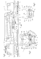
- a machine 1 is shown with a machine frame 2, the Can be moved on a track 5 via rail carriages 3 with flanged wheels 4 is.
- the machine frame 2 is at the end with a driving or working cabin 6.7 provided, the cabin 7 with a measuring bracket 8 and a central control device 9 is equipped.
- a motor 10 is for the Power supply for a travel drive 11 and all other drives to be described Drives of the machine 1 are provided.
- a jib crane 12 is attached to a vertical axis 13 is rotatably supported and 14 height and side adjustable via drives Boom arms 15.
- a bracket 16 At the free end of the extreme Cantilever arm 15 is a bracket 16 for optional connection with work tools (not shown) or a work basket.
- this counter-load 17 has the shape of a plate 18, which are perpendicular to the machine longitudinal direction
- Cross section has a broad side 33 and a narrow side 34 and the in Rest or transfer position 19 of the counterweight 17 (shown in full lines) with the broad side 33 rests on the machine frame 2.
- a center of gravity 20 of the counterweight 17 within a region A which is spaced apart from one another in the cross-machine direction Wheel contact points 21 of the flanged wheels 4 is defined (Fig. 2).
- Swivel device 22 There is one on each of the two long sides of the machine frame 2 Swivel device 22 arranged which is parallel to the machine longitudinal direction extending pivot axis 23.
- the two swivel devices 22 each serve to pivot the counter-load 17 about the aforementioned Swivel axis 23 from the transfer position 19, in which the plate 18th with the broad side 33 parallel to one formed by the wheel contact points 21
- Level 26 is aligned in a counterweight position 24, in which the Broadside runs perpendicular to plane 26.
- the two possible counter load positions 24 are indicated in dash-dotted lines in FIG. 2.
- each swivel device 22 Swivel drive 25 assigned to the - the respective swivel device 22 opposite - long side of the machine frame 2 as well is articulated on the counter load 17 or plate 18.
- a remote-controllable coupling device 27 is provided, which enables an optional coupling with the plate 18.
- each pivot axis 23 of each pivot device 22 by three spaced apart in the machine longitudinal direction Articulation points 28, on the basis of which the counter-load 17 with the machine frame 2 is pivotally connectable.
- Each articulation point 28 consists of the counter load 17 and flanges 29 attached to the machine frame 2 via a in the machine longitudinal direction or in the direction of the pivot axis 23 extending shaft 30 are connected.
- each shaft 30 is displaceable in its longitudinal direction or can be pulled out of the flanges 29, so that the optional manufacture a positive connection of the swivel device 22 or the machine frame 2 with the counter load 17.
- the jib crane 12 is used, for example, when working on the machine 1 together with a work basket attached to it swung out to the side such as inspecting the underside of a track bridge. To the resulting counteract lateral tilting moment, the counter load 17 on the machine side opposite the tipping edge into the vertical Counterweight position 24 pivoted up. To do this, the respective Coupling devices 31 activated by the control device 9 to the To engage articulation points 28 on the side of the counterweight position 24 and at the same time the articulation points of the opposite one in the cross machine direction To solve pivot device 22.
- the coupling devices 27 of the swivel drives 25 are also acted upon accordingly, around the swivel drive 25 required for pivoting the counter load 17 to couple and at the same time the other rotary drive 25 to solve or decouple the counterweight 17. After that it can Swing up the counter load 17 into the counter load position 24, in of the counter-load 17 entirely within a (in dash-double-dotted Lines shown) clearance profile 32 of the track 5 is positioned.
- the application of the coupling devices 27 and 31 and the Swivel drive 25 can be initiated manually or fully automatically.
- the control device 9 can e.g. be designed so that when a certain one is reached, by the lateral pivoting of the Jib crane 12 caused load moment the crane 12 stopped automatically to avoid the risk of the machine 1 tipping over. Then the counter load 17 is automatically in the required counter load position 24 brought on the long side of the machine opposite the crane and then the pivoting of the crane 12 continued.
- each swivel device 22 have a plurality of swivel drives 25 which can be acted upon parallel to one another.
- FIG. 3 shows a further example of an embodiment according to the invention, in which, for the sake of simplicity, functionally identical parts are provided with the same reference numerals as in FIGS. 1 and 2.
- a single pivoting device 22 is provided, with which a counter load 17 can optionally be moved from the transfer position 19 into the two possible counter load positions 24 located on the two long sides of the machine frame 2.
- the counter load 17 together with the swivel device 22, which has the swivel axis 23 and the swivel drive 25, is arranged on a support frame 35. This, in turn , is rotatably mounted on the machine frame 2 about a vertical axis 36 at an angle of 180 °.
- This turntable-like design makes it possible, in a simple manner, to pivot the counter-load 17 after corresponding horizontal rotation of the support frame 35 by means of a rotary drive 37 on the longitudinal side of the machine - opposite the respective tilting edge in the cross-machine direction - into the vertical counter-load position 24 located within the clearance profile 32.
Landscapes
- Engineering & Computer Science (AREA)
- Mechanical Engineering (AREA)
- Life Sciences & Earth Sciences (AREA)
- Sustainable Development (AREA)
- Sustainable Energy (AREA)
- Power Engineering (AREA)
- Transportation (AREA)
- Jib Cranes (AREA)
Priority Applications (1)
| Application Number | Priority Date | Filing Date | Title |
|---|---|---|---|
| AT98890170T ATE245124T1 (de) | 1997-07-02 | 1998-06-04 | Maschine mit einem drehbar gelagerten auslegerkran |
Applications Claiming Priority (3)
| Application Number | Priority Date | Filing Date | Title |
|---|---|---|---|
| AT113897 | 1997-07-02 | ||
| AT113897 | 1997-07-02 | ||
| AT1138/97 | 1997-07-02 |
Publications (3)
| Publication Number | Publication Date |
|---|---|
| EP0888998A2 true EP0888998A2 (fr) | 1999-01-07 |
| EP0888998A3 EP0888998A3 (fr) | 2000-09-06 |
| EP0888998B1 EP0888998B1 (fr) | 2003-07-16 |
Family
ID=3507424
Family Applications (1)
| Application Number | Title | Priority Date | Filing Date |
|---|---|---|---|
| EP98890170A Expired - Lifetime EP0888998B1 (fr) | 1997-07-02 | 1998-06-04 | Machine avec une grue à flèche orientable |
Country Status (7)
| Country | Link |
|---|---|
| EP (1) | EP0888998B1 (fr) |
| CN (1) | CN1084710C (fr) |
| AT (1) | ATE245124T1 (fr) |
| CZ (1) | CZ286613B6 (fr) |
| DE (1) | DE59809011D1 (fr) |
| ES (1) | ES2202794T3 (fr) |
| PL (1) | PL190586B1 (fr) |
Cited By (1)
| Publication number | Priority date | Publication date | Assignee | Title |
|---|---|---|---|---|
| CN111422764A (zh) * | 2020-04-30 | 2020-07-17 | 三一汽车起重机械有限公司 | 起重机配重结构及汽车起重机 |
Family Cites Families (3)
| Publication number | Priority date | Publication date | Assignee | Title |
|---|---|---|---|---|
| DE1807058A1 (de) * | 1968-11-05 | 1970-05-27 | Krupp Gmbh | Autokran |
| US4132317A (en) * | 1977-04-12 | 1979-01-02 | Spetsialnoe Konstruktorskoe Bjuro Gazstroimashina | Pipe laying crane |
| DD275036A1 (de) * | 1988-08-25 | 1990-01-10 | Schwermasch Kirow Veb K | Gegenlastanordnung fuer auslegerkrane |
-
1998
- 1998-06-04 EP EP98890170A patent/EP0888998B1/fr not_active Expired - Lifetime
- 1998-06-04 DE DE59809011T patent/DE59809011D1/de not_active Expired - Lifetime
- 1998-06-04 AT AT98890170T patent/ATE245124T1/de active
- 1998-06-04 ES ES98890170T patent/ES2202794T3/es not_active Expired - Lifetime
- 1998-06-09 PL PL98326789A patent/PL190586B1/pl unknown
- 1998-06-25 CZ CZ19982029A patent/CZ286613B6/cs not_active IP Right Cessation
- 1998-06-30 CN CN98115619A patent/CN1084710C/zh not_active Expired - Fee Related
Cited By (1)
| Publication number | Priority date | Publication date | Assignee | Title |
|---|---|---|---|---|
| CN111422764A (zh) * | 2020-04-30 | 2020-07-17 | 三一汽车起重机械有限公司 | 起重机配重结构及汽车起重机 |
Also Published As
| Publication number | Publication date |
|---|---|
| PL190586B1 (pl) | 2005-12-30 |
| DE59809011D1 (de) | 2003-08-21 |
| PL326789A1 (en) | 1999-01-04 |
| CN1205978A (zh) | 1999-01-27 |
| CN1084710C (zh) | 2002-05-15 |
| ES2202794T3 (es) | 2004-04-01 |
| CZ286613B6 (cs) | 2000-05-17 |
| EP0888998B1 (fr) | 2003-07-16 |
| EP0888998A3 (fr) | 2000-09-06 |
| CZ202998A3 (cs) | 1999-01-13 |
| ATE245124T1 (de) | 2003-08-15 |
Similar Documents
| Publication | Publication Date | Title |
|---|---|---|
| DE202009011577U1 (de) | Kran | |
| DE19748949A1 (de) | Fahrwerk einer Hebevorrichtung | |
| DD292492A5 (de) | Fahrbare gleisstopf-, nivellier- und richtmaschine | |
| EP0675069B1 (fr) | Machine pour voie ferroviaire avec grue pivotante | |
| WO2016150568A1 (fr) | Grue mobile | |
| EP1580331B1 (fr) | Chassis pour machines mobiles de travaux publics | |
| EP0386398A1 (fr) | Machine mobile pour bourrer, niveler et dresser les voies ferrées comprenant des unités de bourrage pivotantes | |
| EP1706305B1 (fr) | Vehicule comportant une plate-forme de travail | |
| EP0085304A1 (fr) | Dispositif pour former des joints dans des chaussées et revêtements de sol similaires | |
| DE4220456C1 (de) | Schienenschleifmaschine | |
| EP1400629B1 (fr) | Machine de meulage pour rails, notamment pour des rails de grue pour conteneur | |
| DE29915801U1 (de) | Vorrichtung zum Ergreifen von Langschienen | |
| EP0801022A2 (fr) | Machine pour travailler aux voies ferrées avec une grue tournante | |
| DE3824575C2 (fr) | ||
| DE2027777C3 (de) | Vorrichtung zum Überführen von Fahrzeugen von einem ersten Gleis auf ein seitlich anschließendes zweites Gleis | |
| EP0888998B1 (fr) | Machine avec une grue à flèche orientable | |
| AT514122B1 (de) | Baumaschine und Verfahren zum Betreiben der Baumaschine | |
| DE3924792A1 (de) | Reifenmontiergeraet | |
| WO2021204507A1 (fr) | Chariot de manutention | |
| DE3915771A1 (de) | Gegenlastanordnung fuer auslegerkrane | |
| EP1185846B1 (fr) | Dispositif d'equilibrage | |
| DE9417893U1 (de) | Mähmaschine | |
| DE9204888U1 (de) | Selbstzentrierende Gruppe | |
| DE3032351C2 (de) | Gleisstopfmaschine | |
| DE4008769C2 (de) | Kraftfahrzeug zum Verlegen einer Festbrücke |
Legal Events
| Date | Code | Title | Description |
|---|---|---|---|
| PUAI | Public reference made under article 153(3) epc to a published international application that has entered the european phase |
Free format text: ORIGINAL CODE: 0009012 |
|
| AK | Designated contracting states |
Kind code of ref document: A2 Designated state(s): AT CH DE FI GB IT LI Kind code of ref document: A2 Designated state(s): AT BE CH DE ES FI FR GB IT LI NL SE |
|
| AX | Request for extension of the european patent |
Free format text: AL;LT;LV;MK;RO;SI |
|
| PUAL | Search report despatched |
Free format text: ORIGINAL CODE: 0009013 |
|
| AK | Designated contracting states |
Kind code of ref document: A3 Designated state(s): AT BE CH CY DE DK ES FI FR GB GR IE IT LI LU MC NL PT SE |
|
| AX | Request for extension of the european patent |
Free format text: AL;LT;LV;MK;RO;SI |
|
| 17P | Request for examination filed |
Effective date: 20010110 |
|
| AKX | Designation fees paid |
Free format text: AT CH DE FI GB IT LI |
|
| RBV | Designated contracting states (corrected) |
Designated state(s): AT BE CH DE ES FI FR GB IT LI NL SE |
|
| GRAH | Despatch of communication of intention to grant a patent |
Free format text: ORIGINAL CODE: EPIDOS IGRA |
|
| GRAH | Despatch of communication of intention to grant a patent |
Free format text: ORIGINAL CODE: EPIDOS IGRA |
|
| GRAH | Despatch of communication of intention to grant a patent |
Free format text: ORIGINAL CODE: EPIDOS IGRA |
|
| GRAA | (expected) grant |
Free format text: ORIGINAL CODE: 0009210 |
|
| AK | Designated contracting states |
Designated state(s): AT BE CH DE ES FI FR GB IT LI NL SE |
|
| REG | Reference to a national code |
Ref country code: GB Ref legal event code: FG4D Free format text: NOT ENGLISH |
|
| REG | Reference to a national code |
Ref country code: CH Ref legal event code: EP |
|
| GBT | Gb: translation of ep patent filed (gb section 77(6)(a)/1977) |
Effective date: 20030716 |
|
| REF | Corresponds to: |
Ref document number: 59809011 Country of ref document: DE Date of ref document: 20030821 Kind code of ref document: P |
|
| REG | Reference to a national code |
Ref country code: SE Ref legal event code: TRGR |
|
| ET | Fr: translation filed | ||
| REG | Reference to a national code |
Ref country code: ES Ref legal event code: FG2A Ref document number: 2202794 Country of ref document: ES Kind code of ref document: T3 |
|
| PLBE | No opposition filed within time limit |
Free format text: ORIGINAL CODE: 0009261 |
|
| STAA | Information on the status of an ep patent application or granted ep patent |
Free format text: STATUS: NO OPPOSITION FILED WITHIN TIME LIMIT |
|
| 26N | No opposition filed |
Effective date: 20040419 |
|
| REG | Reference to a national code |
Ref country code: DE Ref legal event code: R082 Ref document number: 59809011 Country of ref document: DE Representative=s name: RAU, SCHNECK & HUEBNER PATENTANWAELTE RECHTSAN, DE |
|
| REG | Reference to a national code |
Ref country code: DE Ref legal event code: R082 Ref document number: 59809011 Country of ref document: DE Representative=s name: RAU, SCHNECK & HUEBNER PATENTANWAELTE RECHTSAN, DE Effective date: 20141001 Ref country code: DE Ref legal event code: R081 Ref document number: 59809011 Country of ref document: DE Owner name: PLASSER & THEURER, EXPORT VON BAHNBAUMASCHINEN, AT Free format text: FORMER OWNER: FRANZ PLASSER BAHNBAUMASCHINEN-INDUSTRIEGESELLSCHAFT M.B.H., WIEN, AT Effective date: 20141001 |
|
| REG | Reference to a national code |
Ref country code: FR Ref legal event code: PLFP Year of fee payment: 18 |
|
| PGFP | Annual fee paid to national office [announced via postgrant information from national office to epo] |
Ref country code: ES Payment date: 20150512 Year of fee payment: 18 Ref country code: FI Payment date: 20150512 Year of fee payment: 18 Ref country code: SE Payment date: 20150522 Year of fee payment: 18 |
|
| PGFP | Annual fee paid to national office [announced via postgrant information from national office to epo] |
Ref country code: BE Payment date: 20150522 Year of fee payment: 18 Ref country code: FR Payment date: 20150522 Year of fee payment: 18 Ref country code: NL Payment date: 20150522 Year of fee payment: 18 |
|
| PGFP | Annual fee paid to national office [announced via postgrant information from national office to epo] |
Ref country code: DE Payment date: 20150819 Year of fee payment: 18 |
|
| PGFP | Annual fee paid to national office [announced via postgrant information from national office to epo] |
Ref country code: IT Payment date: 20150625 Year of fee payment: 18 |
|
| PGFP | Annual fee paid to national office [announced via postgrant information from national office to epo] |
Ref country code: GB Payment date: 20160419 Year of fee payment: 19 Ref country code: CH Payment date: 20160510 Year of fee payment: 19 |
|
| PGFP | Annual fee paid to national office [announced via postgrant information from national office to epo] |
Ref country code: AT Payment date: 20160519 Year of fee payment: 19 |
|
| PG25 | Lapsed in a contracting state [announced via postgrant information from national office to epo] |
Ref country code: BE Free format text: LAPSE BECAUSE OF NON-PAYMENT OF DUE FEES Effective date: 20160630 |
|
| REG | Reference to a national code |
Ref country code: DE Ref legal event code: R119 Ref document number: 59809011 Country of ref document: DE |
|
| PG25 | Lapsed in a contracting state [announced via postgrant information from national office to epo] |
Ref country code: FI Free format text: LAPSE BECAUSE OF NON-PAYMENT OF DUE FEES Effective date: 20160604 |
|
| REG | Reference to a national code |
Ref country code: SE Ref legal event code: EUG |
|
| REG | Reference to a national code |
Ref country code: NL Ref legal event code: MM Effective date: 20160701 |
|
| PG25 | Lapsed in a contracting state [announced via postgrant information from national office to epo] |
Ref country code: SE Free format text: LAPSE BECAUSE OF NON-PAYMENT OF DUE FEES Effective date: 20160605 |
|
| REG | Reference to a national code |
Ref country code: FR Ref legal event code: ST Effective date: 20170228 |
|
| PG25 | Lapsed in a contracting state [announced via postgrant information from national office to epo] |
Ref country code: FR Free format text: LAPSE BECAUSE OF NON-PAYMENT OF DUE FEES Effective date: 20160630 Ref country code: DE Free format text: LAPSE BECAUSE OF NON-PAYMENT OF DUE FEES Effective date: 20170103 |
|
| PG25 | Lapsed in a contracting state [announced via postgrant information from national office to epo] |
Ref country code: NL Free format text: LAPSE BECAUSE OF NON-PAYMENT OF DUE FEES Effective date: 20160701 |
|
| PG25 | Lapsed in a contracting state [announced via postgrant information from national office to epo] |
Ref country code: IT Free format text: LAPSE BECAUSE OF NON-PAYMENT OF DUE FEES Effective date: 20160604 |
|
| REG | Reference to a national code |
Ref country code: CH Ref legal event code: PL |
|
| REG | Reference to a national code |
Ref country code: AT Ref legal event code: MM01 Ref document number: 245124 Country of ref document: AT Kind code of ref document: T Effective date: 20170604 |
|
| GBPC | Gb: european patent ceased through non-payment of renewal fee |
Effective date: 20170604 |
|
| PG25 | Lapsed in a contracting state [announced via postgrant information from national office to epo] |
Ref country code: LI Free format text: LAPSE BECAUSE OF NON-PAYMENT OF DUE FEES Effective date: 20170630 Ref country code: CH Free format text: LAPSE BECAUSE OF NON-PAYMENT OF DUE FEES Effective date: 20170630 Ref country code: GB Free format text: LAPSE BECAUSE OF NON-PAYMENT OF DUE FEES Effective date: 20170604 |
|
| REG | Reference to a national code |
Ref country code: ES Ref legal event code: FD2A Effective date: 20180507 |
|
| PG25 | Lapsed in a contracting state [announced via postgrant information from national office to epo] |
Ref country code: AT Free format text: LAPSE BECAUSE OF NON-PAYMENT OF DUE FEES Effective date: 20170604 Ref country code: ES Free format text: LAPSE BECAUSE OF NON-PAYMENT OF DUE FEES Effective date: 20160605 |