EP0886889B1 - Breitbandige gedruckte gruppenantenne - Google Patents
Breitbandige gedruckte gruppenantenne Download PDFInfo
- Publication number
- EP0886889B1 EP0886889B1 EP97952073A EP97952073A EP0886889B1 EP 0886889 B1 EP0886889 B1 EP 0886889B1 EP 97952073 A EP97952073 A EP 97952073A EP 97952073 A EP97952073 A EP 97952073A EP 0886889 B1 EP0886889 B1 EP 0886889B1
- Authority
- EP
- European Patent Office
- Prior art keywords
- antenna
- patches
- lines
- array antenna
- centre
- Prior art date
- Legal status (The legal status is an assumption and is not a legal conclusion. Google has not performed a legal analysis and makes no representation as to the accuracy of the status listed.)
- Expired - Lifetime
Links
Images


Classifications
-
- H—ELECTRICITY
- H01—ELECTRIC ELEMENTS
- H01Q—ANTENNAS, i.e. RADIO AERIALS
- H01Q21/00—Antenna arrays or systems
- H01Q21/06—Arrays of individually energised antenna units similarly polarised and spaced apart
-
- H—ELECTRICITY
- H01—ELECTRIC ELEMENTS
- H01Q—ANTENNAS, i.e. RADIO AERIALS
- H01Q21/00—Antenna arrays or systems
- H01Q21/06—Arrays of individually energised antenna units similarly polarised and spaced apart
- H01Q21/061—Two dimensional planar arrays
- H01Q21/065—Patch antenna array
-
- H—ELECTRICITY
- H01—ELECTRIC ELEMENTS
- H01Q—ANTENNAS, i.e. RADIO AERIALS
- H01Q21/00—Antenna arrays or systems
- H01Q21/06—Arrays of individually energised antenna units similarly polarised and spaced apart
- H01Q21/22—Antenna units of the array energised non-uniformly in amplitude or phase, e.g. tapered array or binomial array
Definitions
- the present invention relates to a printed network antenna wide band intended to provide a main lobe substantially of revolution around an axis passing through its center.
- pellet antennas in Anglo-Saxon literature
- Anglo-Saxon literature are still little used despite their interest, due to the ease of realization by known techniques for manufacturing printed circuits.
- An object of the invention is therefore a printed network antenna of small footprint thanks to the use of tablets and having a substantially revolution diagram over a very wide band.
- a printed network antenna is therefore provided.
- wide band to provide a substantially revolving main lobe around an axis passing through the center (A) of the antenna, said antenna comprising a plurality of substantially square radiating pellets supplied by microstrip lines. Feeding by said lines from the center (A) of the antenna is of the tree type. Each pellet is fed at an angle by one of said lines which partially overlaps said angle.
- the distribution of the pellets is not periodic so as to limit the side lobes in the radiation pattern of the antenna and to spread the network lobes, the pads on the periphery of the antenna in this direction having a spacing greater than that of the pellets towards the center of the antenna.
- FIG. 1 is a plan view of the antenna according to the invention.
- This antenna 1 uses a network of pads ("patch") 10.11 distributed over a area limited here by an octagon without this being in any way limiting.
- These pellets are powered by a network of power lines 40 from from a central point A where the signal is applied, for example via of a coaxial.
- FIGS. 2 and 3 are partial sections through the antenna 1.
- the antenna is produced using the printed circuit technique and includes a first dielectric layer 12, for example made of polypropylene, one side of which carries a metallization 13 serving as a ground plane and the other face of which comprises the pellets 10 (one of them is shown).
- a layer of dielectric foam 3 much more thick which in turn carries a second dielectric layer 2, by example in epoxy glass, the face of which in contact with the foam bears parasites 20 opposite each of the pellets 10.
- These parasites have preferably the same shape as the pellets but are smaller and allow to broaden the bandwidth of the antenna.
- the thickness h2 of the dielectric foam layer 3 is preferably three to four times the thickness h3 of the first layer dielectric 12. Thanks to this structure, the second dielectric layer 2 carrying the parasites also serves as a radome for the antenna.
- Figure 3 shows, in plan view, a pellet 10 and its supply.
- This patch is square, side a ; opposite it is the corresponding parasite 20 on side b smaller than a .
- the pellet is supplied at an angle through its angle 100 which is connected to the line 40 at 90 ° from the diagonal of the pellet.
- the size of the overlap between line and patch makes it possible in particular to adapt the impedance of the assembly.
- the advantage of the angle feed with a tree feed as shown in Figure 1 is that this eliminates for each pastille an elbow on the line, which would otherwise be necessary if the departure of line 40 from the angle 100 was made in the direction of the diagonal of the patch leading to the angle. This eliminates a significant cause of losses due to elbows on the entire network.
- the distribution of the pellets on the antenna could be done periodically as is classic in network antennas.
- the pads 10 of the center of the antenna are distributed periodically with a periodicity of 0.8 ⁇ , where ⁇ is the central wavelength of the antenna bandwidth, and the pads 11 from the periphery in the direction of field E have a greater spacing, for example 0.9 ⁇ .
- ⁇ is the central wavelength of the antenna bandwidth
- the pads 11 from the periphery in the direction of field E have a greater spacing, for example 0.9 ⁇ .
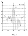
- the level of the lobes secondary is always less than -16 dB.
- a network antenna with small footprint and weight, with protection by radome with protection by radome, a very wide bandwidth (greater than 10% for a R O S ⁇ 1.5), a diagram of radiation of revolution and a weak level of side lobes.
- the antenna according to the invention is little sensitive to the positioning of parasites which widen the bandwidth.
- the tree feeding of the pellets by an angle reduces the losses.
Landscapes
- Waveguide Aerials (AREA)
- Variable-Direction Aerials And Aerial Arrays (AREA)
- Details Of Aerials (AREA)
Claims (8)
- Gedruckte Breitband-Netzantenne zur Lieferung einer bezüglich einer durch das Zentrum (A) der Antenne verlaufenden Achse im wesentlichen drehsymmetrischen Hauptkeule, wobei die Antenne mehrere im wesentlichen quadratisch geformte strahlende Flecken (10, 11) enthält, die über Mikrostrip-Leitungen (40) gespeist werden, und wobei die Speisung der Mikrostrip-Leitungen (40) vom Zentrum (A) der Antenne ausgehend sich baumförmig verzweigt und jeder Fleck (10, 11) an einer Ecke durch eine der Leitungen (40) gespeist wird, dadurch gekennzeichnet, daß die einen Fleck an einer Ecke speisende Leitung diese Ecke (100) teilweise überlappt und daß die Verteilung der Flecken gemäß mindestens einer Richtung (E, H, D) der Antennenebene nichtperiodisch ist, sodaß die Nebenkeulen im Strahlungsdiagramm der Antenne begrenzt werden und die Keulen des Netzes einen Abstand voneinander bekommen, wobei die Flecken (11) an der Peripherie der Antenne in dieser Richtung einen größeren Abstand als die Flecken (10) im Zentrum der Antenne besitzen.
- Netzantenne nach Anspruch 1, dadurch gekennzeichnet, daß die erwähnte Richtung diejenige der Ebene E der Antenne ist.
- Netzantenne nach einem beliebigen der Ansprüche 1 und 2, dadurch gekennzeichnet, daß die Speiseleitungen so ausgebildet sind, daß sie die von jedem Fleck (10, 11) abgestrahlte Energie so gewichten, daß eine im wesentliche drehsymmetrische Hauptkeule in einem großen Frequenzband erzielt wird.
- Antenne nach einem beliebigen der Ansprüche 1 bis 3, dadurch gekennzeichnet, daß die Antenne in zwei Gruppen von zwei aufeinanderfolgenden Sektoren unterteilt ist, wobei jeder Sektor baumförmig ausgehend von einer Hauptleitung (41 bis 44) gespeist wird und die Hauptleitungen (41, 44; 42, 43) der Sektoren einer Gruppe über eine zentrale Leitung (45; 46) miteinander verbunden sind, und daß die Speisung ausgehend vom Zentrum (A) der Antenne über eine Verteilungsleitung (47) erfolgt, die dieses- Zentrum (A) mit den zentralen Leitungen der beiden Gruppen verbindet.
- Netzantenne nach einem beliebigen der Ansprüche 1 bis 4, dadurch gekennzeichnet, daß sie eine erste dielektrische Schicht (12), deren eine Seite mit einer MasseSchicht (13) bedeckt ist und deren andere Seite die Flecken (10, 11) und die Speiseleitungen (40), dann eine Lage (3) aus dielektrischem Schaum und schließlich eine zweite dielektrische Schicht (2) trägt, deren zur Schaumlage gerichtete Seite den Flecken gegenüberliegend Parasiten (20) gleicher Form wie diese aufweist, die das Durchlaßband der Antenne verbreitern.
- Netzantenne nach Anspruch 5, dadurch gekennzeichnet, daß die Parasiten (20) geringere Abmessungen als die entsprechenden Flecken (10, 11) aufweisen.
- Netzantenne nach einem der Ansprüche 5 und 6, dadurch gekennzeichnet, daß die zweite dielektrische Schicht (2) aus Epoxy-Glas ist, um als Radom für die Antenne zu dienen.
- Netzantenne nach Anspruch 7, dadurch gekennzeichnet, daß die erste Schicht (12) aus Polypropylen ist und daß die Dicke (h3) der ersten Schicht (12) drei- bis viermal geringer als die Dicke der Lage (3) aus dielektrischem Schaum ist.
Applications Claiming Priority (3)
| Application Number | Priority Date | Filing Date | Title |
|---|---|---|---|
| FR9615510 | 1996-12-17 | ||
| FR9615510A FR2757315B1 (fr) | 1996-12-17 | 1996-12-17 | Antenne reseau imprimee large bande |
| PCT/FR1997/002314 WO1998027616A1 (fr) | 1996-12-17 | 1997-12-16 | Antenne reseau imprimee large bande |
Publications (2)
| Publication Number | Publication Date |
|---|---|
| EP0886889A1 EP0886889A1 (de) | 1998-12-30 |
| EP0886889B1 true EP0886889B1 (de) | 2003-04-16 |
Family
ID=9498762
Family Applications (1)
| Application Number | Title | Priority Date | Filing Date |
|---|---|---|---|
| EP97952073A Expired - Lifetime EP0886889B1 (de) | 1996-12-17 | 1997-12-16 | Breitbandige gedruckte gruppenantenne |
Country Status (8)
| Country | Link |
|---|---|
| US (1) | US6031491A (de) |
| EP (1) | EP0886889B1 (de) |
| JP (1) | JP2000505978A (de) |
| KR (1) | KR100453030B1 (de) |
| CN (1) | CN1211346A (de) |
| DE (1) | DE69720982T2 (de) |
| FR (1) | FR2757315B1 (de) |
| WO (1) | WO1998027616A1 (de) |
Families Citing this family (30)
| Publication number | Priority date | Publication date | Assignee | Title |
|---|---|---|---|---|
| FR2779578B1 (fr) * | 1998-06-04 | 2002-11-29 | Centre Nat Etd Spatiales | Procede pour la determination des amplitudes et phases des differentes voies d'un reseau d'emission de signaux electromagnetiques, tel qu'une antenne de satellite de telecommunication |
| DE19850895A1 (de) * | 1998-11-05 | 2000-05-11 | Pates Tech Patentverwertung | Mikrowellenantenne mit optimiertem Kopplungsnetzwerk |
| US6208313B1 (en) * | 1999-02-25 | 2001-03-27 | Nortel Networks Limited | Sectoral antenna with changeable sector beamwidth capability |
| US6664932B2 (en) * | 2000-01-12 | 2003-12-16 | Emag Technologies, Inc. | Multifunction antenna for wireless and telematic applications |
| US6388621B1 (en) | 2000-06-20 | 2002-05-14 | Harris Corporation | Optically transparent phase array antenna |
| FR2811142B1 (fr) * | 2000-06-29 | 2002-09-20 | Thomson Multimedia Sa | Dispositif d'emission et/ou de reception d'ondes electromagnetiques alimente par un reseau realise en technologie microruban |
| DE10052748A1 (de) * | 2000-10-25 | 2002-05-29 | Technisat Elektronik Thueringe | Planarantenne mit verbesserter Richtcharakteristik |
| KR100461767B1 (ko) * | 2000-11-28 | 2004-12-14 | 주식회사 마이크로페이스 | 케이유밴드용 마이크로스트립 패치 어레이 안테나 |
| US6667724B2 (en) * | 2001-02-26 | 2003-12-23 | Time Domain Corporation | Impulse radar antenna array and method |
| KR100745043B1 (ko) * | 2001-10-26 | 2007-08-01 | 건수산업 주식회사 | 와이드밴드 통합 안테나 |
| KR100442135B1 (ko) * | 2002-03-19 | 2004-07-30 | 에스케이 텔레콤주식회사 | 이동 통신 기지국용 다중 빔 배열 안테나 장치 |
| US7705782B2 (en) * | 2002-10-23 | 2010-04-27 | Southern Methodist University | Microstrip array antenna |
| US6947008B2 (en) * | 2003-01-31 | 2005-09-20 | Ems Technologies, Inc. | Conformable layered antenna array |
| BR0317194A (pt) * | 2003-01-31 | 2005-11-29 | Ems Technologies Inc | Conjunto conformável de antenas dispostos em camadas |
| US6943749B2 (en) * | 2003-01-31 | 2005-09-13 | M&Fc Holding, Llc | Printed circuit board dipole antenna structure with impedance matching trace |
| US6850197B2 (en) * | 2003-01-31 | 2005-02-01 | M&Fc Holding, Llc | Printed circuit board antenna structure |
| US7345632B2 (en) * | 2003-02-12 | 2008-03-18 | Nortel Networks Limited | Multibeam planar antenna structure and method of fabrication |
| EP1645009A1 (de) * | 2003-07-16 | 2006-04-12 | Huber + Suhner Ag | Dual polarisierte microstrip-patch-antenne |
| TWM260885U (en) * | 2004-07-09 | 2005-04-01 | Inpaq Technology Co Ltd | Antenna structure |
| US7423605B2 (en) * | 2006-01-13 | 2008-09-09 | Research In Motion Limited | Mobile wireless communications device including an electrically conductive director element and related methods |
| EP2081251B1 (de) * | 2008-01-15 | 2018-07-11 | HMD Global Oy | Patchantenne |
| EP2315312A1 (de) * | 2009-10-22 | 2011-04-27 | Toyota Motor Europe NV | Antenne mit schwach besetzter Gruppe von Elementen |
| DE102010040809A1 (de) | 2010-09-15 | 2012-03-15 | Robert Bosch Gmbh | Planare Gruppenantenne mit in mehreren Ebenen angeordneten Antennenelementen |
| US9124006B2 (en) * | 2011-03-11 | 2015-09-01 | Autoliv Asp, Inc. | Antenna array for ultra wide band radar applications |
| KR101338787B1 (ko) | 2012-02-09 | 2013-12-06 | 주식회사 에이스테크놀로지 | 레이더 배열 안테나 |
| CN103311663B (zh) * | 2013-05-16 | 2015-03-04 | 厦门大学 | 带加载孔的高阶改进型树状分形超宽带陷波天线 |
| CN103646144B (zh) * | 2013-12-19 | 2017-03-08 | 西安电子科技大学 | 非周期阵列天线设计方法 |
| KR102063826B1 (ko) | 2014-01-23 | 2020-01-08 | 엘지이노텍 주식회사 | 레이더 시스템의 안테나 장치 |
| CN105322291B (zh) * | 2014-07-24 | 2019-07-23 | 深圳光启创新技术有限公司 | 微带阵列天线 |
| JP2016127453A (ja) * | 2015-01-05 | 2016-07-11 | 株式会社東芝 | アレーアンテナ装置 |
Family Cites Families (10)
| Publication number | Priority date | Publication date | Assignee | Title |
|---|---|---|---|---|
| US4052723A (en) * | 1976-04-26 | 1977-10-04 | Westinghouse Electric Corporation | Randomly agglomerated subarrays for phased array radars |
| US4083050A (en) * | 1976-09-01 | 1978-04-04 | The Bendix Corporation | Dual band monopole omni antenna |
| US4686535A (en) * | 1984-09-05 | 1987-08-11 | Ball Corporation | Microstrip antenna system with fixed beam steering for rotating projectile radar system |
| US4560445A (en) * | 1984-12-24 | 1985-12-24 | Polyonics Corporation | Continuous process for fabricating metallic patterns on a thin film substrate |
| FR2622055B1 (fr) * | 1987-09-09 | 1990-04-13 | Bretagne Ctre Regl Innova Tran | Antenne plaque microonde, notamment pour radar doppler |
| FR2667730B1 (fr) * | 1990-10-03 | 1993-07-02 | Bretagne Ctre Rgl Tra | Antenne. |
| US5453754A (en) * | 1992-07-02 | 1995-09-26 | The Secretary Of State For Defence In Her Brittanic Majesty's Government Of The United Kingdom Of Great Britain And Northern Ireland | Dielectric resonator antenna with wide bandwidth |
| DE4340825A1 (de) * | 1993-12-01 | 1995-06-08 | Rothe Lutz | Planare Strahleranordnung für den Direktempfang der TV-Signale des direktstrahlenden Satellitensystems TDF 1/2 |
| FR2726127B1 (fr) * | 1994-10-19 | 1996-11-29 | Asulab Sa | Antenne miniaturisee a convertir une tension alternative a une micro-onde et vice-versa, notamment pour des applications horlogeres |
| US5838282A (en) * | 1996-03-22 | 1998-11-17 | Ball Aerospace And Technologies Corp. | Multi-frequency antenna |
-
1996
- 1996-12-17 FR FR9615510A patent/FR2757315B1/fr not_active Expired - Fee Related
-
1997
- 1997-12-16 EP EP97952073A patent/EP0886889B1/de not_active Expired - Lifetime
- 1997-12-16 KR KR10-1998-0706380A patent/KR100453030B1/ko not_active IP Right Cessation
- 1997-12-16 JP JP10527399A patent/JP2000505978A/ja active Pending
- 1997-12-16 US US09/125,110 patent/US6031491A/en not_active Expired - Lifetime
- 1997-12-16 CN CN97192345A patent/CN1211346A/zh active Pending
- 1997-12-16 WO PCT/FR1997/002314 patent/WO1998027616A1/fr active IP Right Grant
- 1997-12-16 DE DE69720982T patent/DE69720982T2/de not_active Expired - Lifetime
Also Published As
| Publication number | Publication date |
|---|---|
| DE69720982T2 (de) | 2004-02-19 |
| CN1211346A (zh) | 1999-03-17 |
| US6031491A (en) | 2000-02-29 |
| WO1998027616A1 (fr) | 1998-06-25 |
| JP2000505978A (ja) | 2000-05-16 |
| FR2757315B1 (fr) | 1999-03-05 |
| EP0886889A1 (de) | 1998-12-30 |
| KR19990082640A (ko) | 1999-11-25 |
| KR100453030B1 (ko) | 2004-12-16 |
| FR2757315A1 (fr) | 1998-06-19 |
| DE69720982D1 (de) | 2003-05-22 |
Similar Documents
| Publication | Publication Date | Title |
|---|---|---|
| EP0886889B1 (de) | Breitbandige gedruckte gruppenantenne | |
| EP0805512B1 (de) | Kompakt gedruckte Antenne mit geringer Strahlung in Elevationsrichtung | |
| EP2564466B1 (de) | Kompaktes strahlungselement mit hohlraumresonatoren | |
| CA2004870C (fr) | Dispositif rayonnant multifrequence | |
| EP0575211B1 (de) | Strahlerelement einer Antenne mit breitbandigem Durchlassbereich und aus derartigen Elementen bestehende Gruppenantenne | |
| EP1407512B1 (de) | Antenne | |
| EP0598656B1 (de) | Elementarstrahler für Gruppenantenne und solche Strahler enthaltende Baugruppe | |
| EP0899814B1 (de) | Strahlende Struktur | |
| EP0667984B1 (de) | Monopolantenne mit platten- und stabstrahlern | |
| FR2683952A1 (fr) | Dispositif d'antenne microruban perfectionne, notamment pour transmissions telephoniques par satellite. | |
| FR2556510A1 (fr) | Antenne periodique plane | |
| FR2960710A1 (fr) | Element rayonnant a double polarisation d'antenne multibande | |
| CA2460820C (fr) | Antenne a large bande ou multi-bandes | |
| FR2714769A1 (fr) | Antenne micro-ruban conique préparée sur un substrat plan, et procédé pour sa préparation. | |
| EP1516392B1 (de) | Drahtantenne | |
| EP2817850B1 (de) | Elektromagnetische bandlückenvorrichtung, verwendung davon in einer antennenvorrichtung und parameterfestlegungsverfahren für die antennenvorrichtung | |
| WO2004027930A1 (fr) | Antenne hélicoïdale à large bande | |
| FR2552273A1 (fr) | Antenne hyperfrequence omnidirectionnelle | |
| EP0477102B1 (de) | Richtnetzwerk mit benachbarten Strahlerelementen für Funkübertragungssystem und Einheit mit einem derartigen Richtnetzwerk | |
| EP0352160B1 (de) | Rundstrahlantenne, insbesondere für die Aussendung von Rundfunk- und Fernsehsignalen im Dezimeterwellengebiet und Strahlungssystem, gebildet aus einer Gruppierung dieser Antennen | |
| EP2610965B1 (de) | Kompakte Breitbandantenne mit doppelter Linearpolarisation | |
| EP0088681B1 (de) | Doppelreflektorantenne mit eingebautem Polarisationswandler | |
| EP0831550B1 (de) | Vielseitige Gruppenantenne | |
| EP1873864A1 (de) | Symmetrische Antenne für Mikrostreifenleitertechnologie |
Legal Events
| Date | Code | Title | Description |
|---|---|---|---|
| PUAI | Public reference made under article 153(3) epc to a published international application that has entered the european phase |
Free format text: ORIGINAL CODE: 0009012 |
|
| 17P | Request for examination filed |
Effective date: 19980812 |
|
| AK | Designated contracting states |
Kind code of ref document: A1 Designated state(s): DE FR GB NL SE |
|
| RAP1 | Party data changed (applicant data changed or rights of an application transferred) |
Owner name: THALES |
|
| GRAG | Despatch of communication of intention to grant |
Free format text: ORIGINAL CODE: EPIDOS AGRA |
|
| 17Q | First examination report despatched |
Effective date: 20020109 |
|
| GRAG | Despatch of communication of intention to grant |
Free format text: ORIGINAL CODE: EPIDOS AGRA |
|
| GRAG | Despatch of communication of intention to grant |
Free format text: ORIGINAL CODE: EPIDOS AGRA |
|
| GRAH | Despatch of communication of intention to grant a patent |
Free format text: ORIGINAL CODE: EPIDOS IGRA |
|
| GRAH | Despatch of communication of intention to grant a patent |
Free format text: ORIGINAL CODE: EPIDOS IGRA |
|
| GRAA | (expected) grant |
Free format text: ORIGINAL CODE: 0009210 |
|
| AK | Designated contracting states |
Designated state(s): DE FR GB NL SE |
|
| REG | Reference to a national code |
Ref country code: GB Ref legal event code: FG4D Free format text: NOT ENGLISH |
|
| REF | Corresponds to: |
Ref document number: 69720982 Country of ref document: DE Date of ref document: 20030522 Kind code of ref document: P |
|
| REG | Reference to a national code |
Ref country code: SE Ref legal event code: TRGR |
|
| GBT | Gb: translation of ep patent filed (gb section 77(6)(a)/1977) |
Effective date: 20030715 |
|
| PLBE | No opposition filed within time limit |
Free format text: ORIGINAL CODE: 0009261 |
|
| STAA | Information on the status of an ep patent application or granted ep patent |
Free format text: STATUS: NO OPPOSITION FILED WITHIN TIME LIMIT |
|
| 26N | No opposition filed |
Effective date: 20040119 |
|
| PGFP | Annual fee paid to national office [announced via postgrant information from national office to epo] |
Ref country code: SE Payment date: 20131211 Year of fee payment: 17 |
|
| PGFP | Annual fee paid to national office [announced via postgrant information from national office to epo] |
Ref country code: NL Payment date: 20131210 Year of fee payment: 17 |
|
| REG | Reference to a national code |
Ref country code: NL Ref legal event code: V1 Effective date: 20150701 |
|
| REG | Reference to a national code |
Ref country code: NL Ref legal event code: V1 Effective date: 20150701 |
|
| PG25 | Lapsed in a contracting state [announced via postgrant information from national office to epo] |
Ref country code: SE Free format text: LAPSE BECAUSE OF NON-PAYMENT OF DUE FEES Effective date: 20141217 |
|
| REG | Reference to a national code |
Ref country code: SE Ref legal event code: EUG |
|
| PG25 | Lapsed in a contracting state [announced via postgrant information from national office to epo] |
Ref country code: NL Free format text: LAPSE BECAUSE OF NON-PAYMENT OF DUE FEES Effective date: 20150701 |
|
| REG | Reference to a national code |
Ref country code: FR Ref legal event code: PLFP Year of fee payment: 19 |
|
| PGFP | Annual fee paid to national office [announced via postgrant information from national office to epo] |
Ref country code: GB Payment date: 20151216 Year of fee payment: 19 Ref country code: DE Payment date: 20151208 Year of fee payment: 19 |
|
| PGFP | Annual fee paid to national office [announced via postgrant information from national office to epo] |
Ref country code: FR Payment date: 20151123 Year of fee payment: 19 |
|
| REG | Reference to a national code |
Ref country code: DE Ref legal event code: R119 Ref document number: 69720982 Country of ref document: DE |
|
| GBPC | Gb: european patent ceased through non-payment of renewal fee |
Effective date: 20161216 |
|
| REG | Reference to a national code |
Ref country code: FR Ref legal event code: ST Effective date: 20170831 |
|
| PG25 | Lapsed in a contracting state [announced via postgrant information from national office to epo] |
Ref country code: FR Free format text: LAPSE BECAUSE OF NON-PAYMENT OF DUE FEES Effective date: 20170102 |
|
| PG25 | Lapsed in a contracting state [announced via postgrant information from national office to epo] |
Ref country code: GB Free format text: LAPSE BECAUSE OF NON-PAYMENT OF DUE FEES Effective date: 20161216 Ref country code: DE Free format text: LAPSE BECAUSE OF NON-PAYMENT OF DUE FEES Effective date: 20170701 |