EP0878237A2 - Bodenteil für einen Brausekopf sowie Brausekopf - Google Patents
Bodenteil für einen Brausekopf sowie Brausekopf Download PDFInfo
- Publication number
- EP0878237A2 EP0878237A2 EP98110812A EP98110812A EP0878237A2 EP 0878237 A2 EP0878237 A2 EP 0878237A2 EP 98110812 A EP98110812 A EP 98110812A EP 98110812 A EP98110812 A EP 98110812A EP 0878237 A2 EP0878237 A2 EP 0878237A2
- Authority
- EP
- European Patent Office
- Prior art keywords
- shower head
- water passage
- passage openings
- projection
- bottom part
- Prior art date
- Legal status (The legal status is an assumption and is not a legal conclusion. Google has not performed a legal analysis and makes no representation as to the accuracy of the status listed.)
- Granted
Links
- 239000007921 spray Substances 0.000 title claims abstract description 9
- 239000013013 elastic material Substances 0.000 claims abstract description 6
- XLYOFNOQVPJJNP-UHFFFAOYSA-N water Substances O XLYOFNOQVPJJNP-UHFFFAOYSA-N 0.000 claims description 80
- 235000008733 Citrus aurantifolia Nutrition 0.000 description 7
- 235000011941 Tilia x europaea Nutrition 0.000 description 7
- 239000004571 lime Substances 0.000 description 7
- 239000012528 membrane Substances 0.000 description 7
- 239000000463 material Substances 0.000 description 4
- 230000015572 biosynthetic process Effects 0.000 description 3
- 238000005422 blasting Methods 0.000 description 2
- 239000002245 particle Substances 0.000 description 2
- 230000001133 acceleration Effects 0.000 description 1
- 238000004140 cleaning Methods 0.000 description 1
- 230000000694 effects Effects 0.000 description 1
- 230000001771 impaired effect Effects 0.000 description 1
- 230000002787 reinforcement Effects 0.000 description 1
- 238000006748 scratching Methods 0.000 description 1
- 230000002393 scratching effect Effects 0.000 description 1
- 239000011343 solid material Substances 0.000 description 1
- 239000008399 tap water Substances 0.000 description 1
- 235000020679 tap water Nutrition 0.000 description 1
Images

Classifications
-
- B—PERFORMING OPERATIONS; TRANSPORTING
- B05—SPRAYING OR ATOMISING IN GENERAL; APPLYING FLUENT MATERIALS TO SURFACES, IN GENERAL
- B05B—SPRAYING APPARATUS; ATOMISING APPARATUS; NOZZLES
- B05B1/00—Nozzles, spray heads or other outlets, with or without auxiliary devices such as valves, heating means
- B05B1/14—Nozzles, spray heads or other outlets, with or without auxiliary devices such as valves, heating means with multiple outlet openings; with strainers in or outside the outlet opening
- B05B1/18—Roses; Shower heads
- B05B1/185—Roses; Shower heads characterised by their outlet element; Mounting arrangements therefor
-
- B—PERFORMING OPERATIONS; TRANSPORTING
- B05—SPRAYING OR ATOMISING IN GENERAL; APPLYING FLUENT MATERIALS TO SURFACES, IN GENERAL
- B05B—SPRAYING APPARATUS; ATOMISING APPARATUS; NOZZLES
- B05B15/00—Details of spraying plant or spraying apparatus not otherwise provided for; Accessories
- B05B15/50—Arrangements for cleaning; Arrangements for preventing deposits, drying-out or blockage; Arrangements for detecting improper discharge caused by the presence of foreign matter
- B05B15/52—Arrangements for cleaning; Arrangements for preventing deposits, drying-out or blockage; Arrangements for detecting improper discharge caused by the presence of foreign matter for removal of clogging particles
- B05B15/528—Arrangements for cleaning; Arrangements for preventing deposits, drying-out or blockage; Arrangements for detecting improper discharge caused by the presence of foreign matter for removal of clogging particles by resilient deformation of the nozzle
-
- B—PERFORMING OPERATIONS; TRANSPORTING
- B05—SPRAYING OR ATOMISING IN GENERAL; APPLYING FLUENT MATERIALS TO SURFACES, IN GENERAL
- B05B—SPRAYING APPARATUS; ATOMISING APPARATUS; NOZZLES
- B05B15/00—Details of spraying plant or spraying apparatus not otherwise provided for; Accessories
- B05B15/60—Arrangements for mounting, supporting or holding spraying apparatus
- B05B15/62—Arrangements for supporting spraying apparatus, e.g. suction cups
Definitions
- the invention relates to a shower head with a water passage openings having bottom part made of an elastic material, the water passage openings Exit at the bottom of the shower head and over the bottom survive.
- shower heads can be found in almost every household as part of a shower head known for decades. Problems arise in particular with shower heads with hard to very hard tap water, from which very quickly and massively Eliminate limescale.
- the limescale deposits set the water passage openings and significantly impair the function of the shower head.
- EP-A-0 435 031 The principle known from EP-A-0 435 031 is based on a similar principle Shower head, at the bottom part of which there are hose-like outlet openings Material with a hardness of 20 to 100 shore are provided. By manual “rubbing" on the hose-like outlet openings should be in these deposited lime can be removed.
- the invention now goes a new way.
- shower head provided that the bottom part has an approximately ring-shaped Has projection that protrudes beyond the underside of the shower head and that the water passage openings along the length of the projection are distributed.
- the at least one ring segment but preferably the shape of a projection having a closed ring no longer carries the risk of damage, which is the case with the aforementioned extensions.
- the water passage openings are reinforced in such a way that the risk of damage to the bottom part when "rubbing" is not more exists.
- the annular projection can be easily made deform by manual “rubbing", whereby the lime particles in the Water passage openings detached and then fall out of them or be washed out.
- the bottom part at least one exposed at the bottom of the shower head at least has a water passage opening having a central section, which as Membrane is formed. Due to the elastic properties of the bottom part and the formation of the central section as a membrane, the water passage openings do not necessarily have to protrude over the underside of the shower head, can be a cleaning of the shower head from the lime particles in particular easily achieved by, for example, a finger over the membrane-like exposed, d. H.
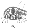
- a shower head 1 according to the invention is shown in cross-sectional view.
- the shower head 1 the basic structure of which is known per se has a water supply 2.
- the shower head 1 is included a water passage openings 3 having bottom part 4.
- the Bottom part 4 consists of elastic material, preferably with a material hardness from 20 to 120 shore.
- the water passage openings 3 occur at the Bottom 5 of the shower head 1.
- the water passage openings 3 are, if at all, only very slightly over the bottom 5 of the shower head 1.
- the bottom part 4 itself is held in the shower head 1 and is in with the water supply 2 Connection.
- the bottom part 4 has at least one approximately ring-shaped Has projection 6, which over the bottom 5 of the shower head 1st protrudes, the water passage openings 3 over the length of the projection 6 are distributed.
- the projection 6 itself has at least one ring segment that extends over at least part of the underside 5 of the shower head 1 extends extensively.
- the projection 6 preferably has the shape of a closed ring on the circumference at the bottom 5 of the shower head 1 is arranged. Otherwise, it is also understood that the projection 6 can have the shape of an open ring.
- the ring-shaped projection which consists of solid material and only is penetrated by the water passage openings in some places due to the material properties of the bottom part 4 easily manually be deformed by "rubbing", which also changes the water passage openings 3 change in shape, which means that it is deposited Lime dissolves and is discharged.
- the water passage openings 3 occur in each case at the highest point of the projection 6, are at least in the circumferential direction surrounded by comparatively much elastic material of the bottom part 4, so that a break or damage to the projection when "rubbing" is not to be feared.
- the shower head 1 offers the water passage openings 3 over the circumference of the projection 6 to distribute evenly. It has been found that it is for good The blasting result is sufficient if the individual water passage openings 3 are spaced apart by an arc angle of 6 °. This way you get 60 Water passage openings 3, due to the function of the invention it is ensured that every 60 water openings after occasional "Rubbing" can be flowed through.
- the projection 6 is annular trained, but also the bottom part 4. So it's not necessarily required that the bottom part 4 over the entire surface of the bottom 5 of the shower head 1 extends. Because of the annular bottom part 4, it is possible the actual shower function in the area of the outer circumference of the shower head 1, while the central area for possible others Functions of the shower head 1 is available.
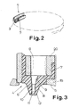
- the bottom part 4 has an area which is approximately U-shaped in cross section 7 on which in the embodiments of FIG. 1 (right representation) and Fig. 2 and 3 of the projection 6 connects.
- the bottom part 4 can be particularly simple Hold in a ring channel 8 provided in the housing of the shower head 1, which will be discussed in more detail below.
- the But bottom part 4 can also be designed as an annular disc to which the projection 6 joins downwards. Instead of a side clamp The bottom part 4 is then corresponding over the U-shaped area To hold or clamp in the housing of the shower head 1.
- the projection 6 is not only movable back and forth, but also in the shower head 1 can be pushed in.
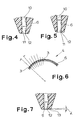
- the water passage openings 3 have a narrowing in the flow direction Section 9 on.
- This narrowing section 9 acts in Art a Venturi nozzle, therefore leads to the acceleration of the water.
- the advantage this narrowing section 9 is that even at a low Amount of water a quite powerful water jet can be generated.
- the narrowing section 9 immediately adjoins the U-shaped one Area 7.
- the narrowing section 9 is in turn connected an outlet section 10.
- the outlet section is in its end region 11 10 beveled according to the desired water outlet direction.
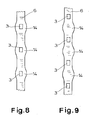
- FIGS. 3, 4 and 5 shows that the outlet section 10 in its end region 11 with different water passage openings 3 can also be designed differently.
- this beam pattern is 10 times in Projection 6 provided so that thirty water passage openings 3 with a Inclination of 8 ° with respect to the vertical, twenty water openings with an inclination of 5 ° and ten water passages with an inclination of 2 ° are provided.
- the one in FIG shown end region 11 has a bevel 12 with an angle of 16 °, so that there is a water jet direction of 8 °.
- 4 shows the bevel 12 in the end region 11 at an angle of 10 °, so that there is a Water jet direction of 5 ° results.
- the water passage openings 3 are designed such that there is an equal flow rate regardless of the water jet direction results. This is realized in that the lower surface of the water passage openings 3 the desired requirements in the area of the outlet accordingly beveled at a small angle ⁇ of 0 to 1 ° is. This results in the area of the bevel 12 subsequent to the End region 11 a protrusion 13 through which the water passage opening narrowed.
- the inside and / or on the outside of the projection 6 and / or the base part 4 at least one bulge 14 provided.
- the bulges 14 are not only aesthetic Effect, because they give the impression of "rubbing" when stripping lime, but also serve to move the annular bottom part 4 to avoid within the shower head 1. 8 also shows and 9 that the water passage openings 3 at least on their outlet side End in a rectangular shape.
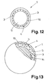
- FIGS. 10 to 13 are other embodiments of the shower head according to the invention 1 shown.
- the bottom part 4 in a lower support element 15 of the shower head 1 inserted and fixed in it.
- the main thing here is that the bottom part 4 has a central section 16 which is designed as a membrane.
- Water passage openings 3 can be aligned as described above.
- the design as a membrane makes it possible, with a correspondingly slight application of pressure to deform the membrane to the central portion 16, which for Removal of the lime deposited there leads.
- the base part 4 an area 7 of approximately U-shaped cross section.
- the middle section 16 lies between the two side legs of the U-shaped Area 7.
- the bottom part 4 is again designed as a ring, which is what the previously mentioned Has advantages.
- the middle section 16 stands over the bottom 5 of the shower head 1 over.
- the middle section 16 presses This is particularly easy if the middle section 16 and the bottom 5 merge into each other.
- the U-shaped region 7 or the bottom part 4 accidentally damaged.
- the central section of the area is also concave or can just be trained.
- a movement of the midsection can result from this result in water flowing through the shower head and the flow pressure on the inside of the central section acts so that it extends outwards bulges. If the water pressure changes now, this occurs due to the membrane properties a corresponding movement of the middle section, which also leads to limescale removal.
- the additional "scratching" to facilitate at least one knob 17 on the outside of the central section 16 may be provided, which over the underside 5 of the shower head 1 survives.
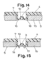
- FIGS. 14 and 15 While the annular design of the base part 4 from FIGS. 12 and 13 14 and 15, another embodiment is shown, in which basically also the central section 16 as a membrane is trained.
- FIGS. 14 and 15 applies to what has been said above with the exception that the bottom part 4 is not considered Ring is formed, has a plurality of middle sections that approximately are distributed over the entire underside 5 of the shower head.
- a plurality of openings 18 are provided in the corresponding Project U-shaped areas 7. Because of the U-shaped design, they are Areas flat and designed so that a user the middle sections 16th (with convex training).
- FIGS. 14 and 15 Concave formation of the middle section 16 applies to what has been said above.
- a collar 19 protruding into the interior of the area 7 is an extension the water passage opening 3 is provided.
- the collar 19 thus represents a reinforcement for the water passage opening 3 towards the inside.
- a corresponding support device 20 provided to fix the annular base parts 4 in the shower head 1 and in the case of a U-shaped design.
- the support device 20 preferably has one circumferential support ring with a plurality of passage openings 21st is provided, as can be seen in particular from FIGS. 10 and 11.
- the Support device 20 clamps the bottom part 4 in the ring channel 8 of the shower head 1 firmly.
- Steps 22 in the U-shaped area 7 for inserting the support device 20 be provided.
Landscapes
- Nozzles (AREA)
- Bathtubs, Showers, And Their Attachments (AREA)
Abstract
Description
- Fig. 1
- eine Querschnittsansicht eines erfindungsgemäßen Brausekopfes, in dem zwei unterschiedliche Ausführungsformen dargestellt sind,
- Fig. 2
- eine perspektivische Querschnittsansicht eines nur teilweise dargestellten erfindungsgemäßen Bodenteils,
- Fig. 3
- eine Querschnittsansicht eines Teils eines erfindungsgemäßen Brausekopfes,
- Fig. 4
- eine Querschnittsansicht eines Teils des Bodenteils mit einer Wasserdurchtrittsöffnung,
- Fig. 5
- eine Querschnittsansicht eines anderen Teils des erfindungsgemäßen Bodenteils mit einer anderen Wasserdurchtrittsöffnung,
- Fig. 6
- eine schematische Darstellung des Strahlbildes des erfindungsgemäßen Brausekopfes,
- Fig. 7
- eine Querschnittsansicht eines Teils des Bodenteils,
- Fig. 8
- eine gestreckte Ansicht eines ringförmigen Vorsprungs des erfindungsgemäßen Bodenteils,
- Fig. 9
- eine weitere gestreckte Ansicht einer anderen Ausführungsform des erfindungsgemäßen Bodenteils,
- Fig. 10
- eine perspektivische Querschnittsansicht eines Teils einer anderen Ausführungsform des erfindungsgemäßen Brausekopfes,
- Fig. 11
- eine der Fig. 9 entsprechende Ansicht einer weiteren Ausführungsform des erfindungsgemäßen Brausekopfes,
- Fig. 12
- eine Unteransicht eines erfindungsgemäßen Brausekopfes,
- Fig. 13
- eine weitere Unteransicht einer anderen Ausführungsform des erfindungsgemäßen Brausekopfes,
- Fig. 14
- eine Querschnittsansicht einer weiteren Ausführungsform des erfindungsgemäßen Brausekopfes und
- Fig. 15
- eine Querschnittsansicht einer weiteren Ausführungsform des erfindungsgemäßen Brausekopfes.
Claims (7)
- Brausekopf (101) mit einem Wasserdurchtrittsöffnungen (103) aufweisenden Bodenteil (104) aus einem elastischen Material, wobei die Wasserdurchtrittsöffnungen (103) an der Unterseite (105) des Brausekopfes (101) austreten und über die Unterseite (105) überstehen, dadurch gekennzeichnet, daß der Bodenteil (104) wenigstens einen etwa ringförmig ausgebildeten Vorsprung (106) aufweist, der über die Unterseite (105) des Brausekopfes (101) übersteht und daß die Wasserdurchtrittsöffnungen (103) über die Länge des Vorsprungs (106) verteilt sind.
- Brausekopf nach Anspruch 1, dadurch gekennzeichnet, daß der Vorsprung (106) wenigstens ein Ringsegment aufweist, vorzugsweise aber die Form eines geschlossenen Ringes hat.
- Brausekopf nach Anspruch 1 oder 2, dadurch gekennzeichnet, daß die Wasserdurchtrittsöffnungen (103) jeweils an der höchsten Stelle des Vorsprungs (106) austreten und daß, vorzugsweise, die Wasserdurchtrittsöffnungen (103) über den Umfang des Vorsprungs (106) gleichmäßig verteilt sind, vorzugsweise um einen Bogenwinkel von 6° beabstandet.
- Brausekopf nach einem der Ansprüche 1 bis 3, dadurch gekennzeichnet, daß der Bodenteil (104) als Ring ausgebildet ist oder zumindest einen ringförmigen Abschnitt aufweist und daß, vorzugsweise, der Bodenteil (104) einen im Querschnitt etwa U-förmig ausgebildeten Bereich (107) aufweist, an den sich der Vorsprung (106) anschließt.
- Brausekopf nach einem der Ansprüche 1 bis 4, dadurch gekennzeichnet, daß die Wasserdurchtrittsöffnungen (103) einen sich in Durchflußrichtung verengenden Abschnitt (109) aufweisen und daß, vorzugsweise, sich an den verengenden Abschnitt (109) ein Austrittsabschnitt (110) anschließt, der entsprechend der Wasserstrahlrichtung eine Anschrägung (112) aufweist.
- Brausekopf nach einem der Ansprüche 1 bis 5, dadurch gekennzeichnet, daß benachbarte Wasserdurchtrittsöffnungen (103) unterschiedliche Wasserstrahlrichtungen aufweisen, daß, vorzugsweise, die Wasserstrahlrichtung der Wasserdurchtrittsöffnungen (103) zwischen 0 und 16° zur Senkrechten liegt, daß, vorzugsweise, benachbarte Wasserdurchtrittsöffnungen (103) ein sich periodisch wiederholendes Strahlbild mit Wasserstrahlrichtungen von 8°, 5°, 8°, 5°, 8° und 2° haben und daß, vorzugsweise, die Wasserdurchtrittsöffnungen (3) derart ausgebildet sind, daß sich unabhängig von der Wasserstrahlrichtung eine gleiche Durchflußrate der einzelnen Wasserdurchtrittsöffnungen (103) ergibt.
- Brausekopf nach einem der Ansprüche 1 bis 6, dadurch gekennzeichnet, daß innenseitig und/oder außenseitig des ringförmigen Bodenteils (104) und/oder des Vorsprungs (106) wenigstens eine seitliche Ausbuchtung (114) vorgesehen ist.
Applications Claiming Priority (5)
| Application Number | Priority Date | Filing Date | Title |
|---|---|---|---|
| DE4404966 | 1994-02-17 | ||
| DE4404966A DE4404966C2 (de) | 1994-02-17 | 1994-02-17 | Bodenteil für einen Brausekopf |
| DE4419696A DE4419696C2 (de) | 1994-06-04 | 1994-06-04 | Brausekopf |
| DE4419696 | 1994-06-04 | ||
| EP95912160A EP0744997B1 (de) | 1994-02-17 | 1995-02-17 | Bodenteil für einen brausekopf sowie brausekopf |
Related Parent Applications (2)
| Application Number | Title | Priority Date | Filing Date |
|---|---|---|---|
| EP95912160A Division-Into EP0744997B1 (de) | 1994-02-17 | 1995-02-17 | Bodenteil für einen brausekopf sowie brausekopf |
| EP95912160.9 Division | 1995-08-24 |
Publications (3)
| Publication Number | Publication Date |
|---|---|
| EP0878237A2 true EP0878237A2 (de) | 1998-11-18 |
| EP0878237A3 EP0878237A3 (de) | 1998-12-30 |
| EP0878237B1 EP0878237B1 (de) | 2001-07-11 |
Family
ID=6510417
Family Applications (1)
| Application Number | Title | Priority Date | Filing Date |
|---|---|---|---|
| EP98110812A Revoked EP0878237B1 (de) | 1994-02-17 | 1995-02-17 | Bodenteil für einen Brausekopf sowie Brausekopf |
Country Status (2)
| Country | Link |
|---|---|
| EP (1) | EP0878237B1 (de) |
| DE (3) | DE4404966C2 (de) |
Cited By (1)
| Publication number | Priority date | Publication date | Assignee | Title |
|---|---|---|---|---|
| WO2004085753A1 (de) | 2003-03-25 | 2004-10-07 | Neoperl Gmbh | Sanitäre wasserauslaufeinheit, insbesondere strahlregler oder brause |
Families Citing this family (3)
| Publication number | Priority date | Publication date | Assignee | Title |
|---|---|---|---|---|
| DE19646655A1 (de) * | 1996-11-12 | 1998-05-14 | Grohe Kg Hans | Brausekopf |
| DE19901554A1 (de) | 1999-01-16 | 2000-07-20 | Hansgrohe Ag | Brausekopf |
| DE102004056070B4 (de) * | 2004-11-15 | 2019-01-31 | Hansgrohe Se | Sanitärer Brausekopf |
Citations (2)
| Publication number | Priority date | Publication date | Assignee | Title |
|---|---|---|---|---|
| EP0435031A2 (de) | 1989-12-28 | 1991-07-03 | Friedrich Grohe Aktiengesellschaft | Brausekopf |
| EP0443538A1 (de) | 1990-02-22 | 1991-08-28 | MASCO GmbH | Brausekopf |
Family Cites Families (9)
| Publication number | Priority date | Publication date | Assignee | Title |
|---|---|---|---|---|
| US2402741A (en) * | 1944-10-03 | 1946-06-25 | Adolphe O Draviner | Spray head |
| US2559894A (en) * | 1948-02-25 | 1951-07-10 | Carl H Nordell | Shower head |
| FR1070363A (fr) * | 1953-02-06 | 1954-07-23 | Appareil à douche | |
| CH645176A5 (fr) * | 1980-11-19 | 1984-09-14 | Kaeser Charles Sa | Dispositif melangeur automatique. |
| DE3044310C2 (de) * | 1980-11-25 | 1984-09-27 | Friedrich Grohe Armaturenfabrik Gmbh & Co, 5870 Hemer | Brauseeinrichtung |
| DE3704782A1 (de) * | 1986-12-04 | 1988-09-15 | Johannes Neuenschwander | Spardusche mit elastischem kopf und sparduese |
| JPH0499243U (de) * | 1991-01-17 | 1992-08-27 | ||
| DE4308599A1 (de) * | 1992-11-04 | 1994-05-05 | Grohe Armaturen Friedrich | Brausekopf |
| DE9310367U1 (de) * | 1993-07-12 | 1993-09-02 | Hamm, Manfred R., Dr., 82544 Egling | Massagebrausekopf mit rotierender noppenbeschichteter Oberfläche |
-
1994
- 1994-02-17 DE DE4404966A patent/DE4404966C2/de not_active Expired - Fee Related
-
1995
- 1995-02-17 EP EP98110812A patent/EP0878237B1/de not_active Revoked
- 1995-02-17 DE DE59509619T patent/DE59509619D1/de not_active Expired - Fee Related
- 1995-02-17 DE DE59509412T patent/DE59509412D1/de not_active Revoked
Patent Citations (2)
| Publication number | Priority date | Publication date | Assignee | Title |
|---|---|---|---|---|
| EP0435031A2 (de) | 1989-12-28 | 1991-07-03 | Friedrich Grohe Aktiengesellschaft | Brausekopf |
| EP0443538A1 (de) | 1990-02-22 | 1991-08-28 | MASCO GmbH | Brausekopf |
Cited By (1)
| Publication number | Priority date | Publication date | Assignee | Title |
|---|---|---|---|---|
| WO2004085753A1 (de) | 2003-03-25 | 2004-10-07 | Neoperl Gmbh | Sanitäre wasserauslaufeinheit, insbesondere strahlregler oder brause |
Also Published As
| Publication number | Publication date |
|---|---|
| DE4404966A1 (de) | 1995-08-31 |
| EP0878237A3 (de) | 1998-12-30 |
| EP0878237B1 (de) | 2001-07-11 |
| DE59509619D1 (de) | 2001-10-25 |
| DE59509412D1 (de) | 2001-08-16 |
| DE4404966C2 (de) | 1997-02-13 |
Similar Documents
| Publication | Publication Date | Title |
|---|---|---|
| DE4105183C2 (de) | Brausekopf | |
| EP0719589A2 (de) | Brausekopf | |
| EP0175881B1 (de) | Spritzdüse für eine Munddusche mit Einfach- bzw. Mehrfachstrahl | |
| EP0719586A2 (de) | Brausekopf | |
| EP0216319A2 (de) | Strahlregler für Wasserhahnmundstücke | |
| DE1913713A1 (de) | Spritzduese | |
| DE112019004251T5 (de) | Wasserauslassdüse und Wasserstrahleinrichtung mit derselben | |
| DE2235217A1 (de) | Duschanlage mit vorrichtung zur regulierung der amplitude des wasserstrahles | |
| DE3832426C2 (de) | ||
| EP0591877A1 (de) | Duscheinrichtung mit selbstreinigendem Duschkopf | |
| EP0878237A2 (de) | Bodenteil für einen Brausekopf sowie Brausekopf | |
| DE69108853T2 (de) | Vorrichtung zur Schlauchentwässerung eines ausziehbaren Brause-anschlusses. | |
| EP0744997B1 (de) | Bodenteil für einen brausekopf sowie brausekopf | |
| DE1927695A1 (de) | Ausflussmundstueck fuer spritzerarme Stroemungen | |
| DE4419696C2 (de) | Brausekopf | |
| DE19646655A1 (de) | Brausekopf | |
| EP0646679A1 (de) | Filtersieb für Wasserauslaufarmaturen | |
| DE69302435T2 (de) | In einem Halter befestigter Alaunstift | |
| EP0885660B1 (de) | Brausekopf | |
| DE10146788B4 (de) | Strahlregler | |
| EP0995373A1 (de) | Reihenverbindung für Mehrzweckstühle | |
| DE2710184C2 (de) | Sperrvorrichtung | |
| DE2111829C3 (de) | Selbstreinigender Sprühkopf | |
| DE3425660A1 (de) | Duese fuer kunststoffspritzmaschinen | |
| DE20115636U1 (de) | Strahlregler |
Legal Events
| Date | Code | Title | Description |
|---|---|---|---|
| PUAI | Public reference made under article 153(3) epc to a published international application that has entered the european phase |
Free format text: ORIGINAL CODE: 0009012 |
|
| PUAL | Search report despatched |
Free format text: ORIGINAL CODE: 0009013 |
|
| 17P | Request for examination filed |
Effective date: 19980713 |
|
| AC | Divisional application: reference to earlier application |
Ref document number: 744997 Country of ref document: EP |
|
| AK | Designated contracting states |
Kind code of ref document: A2 Designated state(s): DE FR IT |
|
| AK | Designated contracting states |
Kind code of ref document: A3 Designated state(s): DE FR IT |
|
| 17Q | First examination report despatched |
Effective date: 19990907 |
|
| GRAG | Despatch of communication of intention to grant |
Free format text: ORIGINAL CODE: EPIDOS AGRA |
|
| GRAG | Despatch of communication of intention to grant |
Free format text: ORIGINAL CODE: EPIDOS AGRA |
|
| GRAH | Despatch of communication of intention to grant a patent |
Free format text: ORIGINAL CODE: EPIDOS IGRA |
|
| RAP1 | Party data changed (applicant data changed or rights of an application transferred) |
Owner name: IDEAL-STANDARD GMBH & CO. OHG |
|
| GRAH | Despatch of communication of intention to grant a patent |
Free format text: ORIGINAL CODE: EPIDOS IGRA |
|
| GRAA | (expected) grant |
Free format text: ORIGINAL CODE: 0009210 |
|
| AC | Divisional application: reference to earlier application |
Ref document number: 744997 Country of ref document: EP |
|
| AK | Designated contracting states |
Kind code of ref document: B1 Designated state(s): DE FR IT |
|
| PG25 | Lapsed in a contracting state [announced via postgrant information from national office to epo] |
Ref country code: IT Free format text: LAPSE BECAUSE OF FAILURE TO SUBMIT A TRANSLATION OF THE DESCRIPTION OR TO PAY THE FEE WITHIN THE PRESCRIBED TIME-LIMIT;WARNING: LAPSES OF ITALIAN PATENTS WITH EFFECTIVE DATE BEFORE 2007 MAY HAVE OCCURRED AT ANY TIME BEFORE 2007. THE CORRECT EFFECTIVE DATE MAY BE DIFFERENT FROM THE ONE RECORDED. Effective date: 20010711 Ref country code: FR Free format text: LAPSE BECAUSE OF FAILURE TO SUBMIT A TRANSLATION OF THE DESCRIPTION OR TO PAY THE FEE WITHIN THE PRESCRIBED TIME-LIMIT Effective date: 20010711 |
|
| REF | Corresponds to: |
Ref document number: 59509412 Country of ref document: DE Date of ref document: 20010816 |
|
| EN | Fr: translation not filed | ||
| PLBI | Opposition filed |
Free format text: ORIGINAL CODE: 0009260 |
|
| PLBF | Reply of patent proprietor to notice(s) of opposition |
Free format text: ORIGINAL CODE: EPIDOS OBSO |
|
| 26 | Opposition filed |
Opponent name: FRIEDRICH GROHE AG & CO. KG Effective date: 20020330 |
|
| PLBF | Reply of patent proprietor to notice(s) of opposition |
Free format text: ORIGINAL CODE: EPIDOS OBSO |
|
| PLBF | Reply of patent proprietor to notice(s) of opposition |
Free format text: ORIGINAL CODE: EPIDOS OBSO |
|
| PLBF | Reply of patent proprietor to notice(s) of opposition |
Free format text: ORIGINAL CODE: EPIDOS OBSO |
|
| PLBQ | Unpublished change to opponent data |
Free format text: ORIGINAL CODE: EPIDOS OPPO |
|
| PLAB | Opposition data, opponent's data or that of the opponent's representative modified |
Free format text: ORIGINAL CODE: 0009299OPPO |
|
| PLBI | Opposition filed |
Free format text: ORIGINAL CODE: 0009260 |
|
| 26 | Opposition filed |
Opponent name: GROHE WATER TECHNOLOGY AG & CO. KG Effective date: 20020330 |
|
| PLAY | Examination report in opposition despatched + time limit |
Free format text: ORIGINAL CODE: EPIDOSNORE2 |
|
| PLAY | Examination report in opposition despatched + time limit |
Free format text: ORIGINAL CODE: EPIDOSNORE2 |
|
| PLAY | Examination report in opposition despatched + time limit |
Free format text: ORIGINAL CODE: EPIDOSNORE2 |
|
| PLAY | Examination report in opposition despatched + time limit |
Free format text: ORIGINAL CODE: EPIDOSNORE2 |
|
| PLAY | Examination report in opposition despatched + time limit |
Free format text: ORIGINAL CODE: EPIDOSNORE2 |
|
| PGFP | Annual fee paid to national office [announced via postgrant information from national office to epo] |
Ref country code: DE Payment date: 20050128 Year of fee payment: 11 |
|
| PLAY | Examination report in opposition despatched + time limit |
Free format text: ORIGINAL CODE: EPIDOSNORE2 |
|
| RDAF | Communication despatched that patent is revoked |
Free format text: ORIGINAL CODE: EPIDOSNREV1 |
|
| RDAG | Patent revoked |
Free format text: ORIGINAL CODE: 0009271 |
|
| STAA | Information on the status of an ep patent application or granted ep patent |
Free format text: STATUS: PATENT REVOKED |
|
| 27W | Patent revoked |
Effective date: 20050807 |