EP0877336A2 - Statusmeldung von Zusatzeinheiten in einem Drucker - Google Patents
Statusmeldung von Zusatzeinheiten in einem Drucker Download PDFInfo
- Publication number
- EP0877336A2 EP0877336A2 EP98108379A EP98108379A EP0877336A2 EP 0877336 A2 EP0877336 A2 EP 0877336A2 EP 98108379 A EP98108379 A EP 98108379A EP 98108379 A EP98108379 A EP 98108379A EP 0877336 A2 EP0877336 A2 EP 0877336A2
- Authority
- EP
- European Patent Office
- Prior art keywords
- unit
- microprocessor
- paper
- printer
- initiation command
- Prior art date
- Legal status (The legal status is an assumption and is not a legal conclusion. Google has not performed a legal analysis and makes no representation as to the accuracy of the status listed.)
- Withdrawn
Links
Images


Classifications
-
- B—PERFORMING OPERATIONS; TRANSPORTING
- B65—CONVEYING; PACKING; STORING; HANDLING THIN OR FILAMENTARY MATERIAL
- B65H—HANDLING THIN OR FILAMENTARY MATERIAL, e.g. SHEETS, WEBS, CABLES
- B65H1/00—Supports or magazines for piles from which articles are to be separated
- B65H1/26—Supports or magazines for piles from which articles are to be separated with auxiliary supports to facilitate introduction or renewal of the pile
- B65H1/266—Support fully or partially removable from the handling machine, e.g. cassette, drawer
-
- B—PERFORMING OPERATIONS; TRANSPORTING
- B65—CONVEYING; PACKING; STORING; HANDLING THIN OR FILAMENTARY MATERIAL
- B65H—HANDLING THIN OR FILAMENTARY MATERIAL, e.g. SHEETS, WEBS, CABLES
- B65H1/00—Supports or magazines for piles from which articles are to be separated
- B65H1/04—Supports or magazines for piles from which articles are to be separated adapted to support articles substantially horizontally, e.g. for separation from top of pile
-
- B—PERFORMING OPERATIONS; TRANSPORTING
- B65—CONVEYING; PACKING; STORING; HANDLING THIN OR FILAMENTARY MATERIAL
- B65H—HANDLING THIN OR FILAMENTARY MATERIAL, e.g. SHEETS, WEBS, CABLES
- B65H3/00—Separating articles from piles
- B65H3/44—Simultaneously, alternately, or selectively separating articles from two or more piles
-
- G—PHYSICS
- G03—PHOTOGRAPHY; CINEMATOGRAPHY; ANALOGOUS TECHNIQUES USING WAVES OTHER THAN OPTICAL WAVES; ELECTROGRAPHY; HOLOGRAPHY
- G03G—ELECTROGRAPHY; ELECTROPHOTOGRAPHY; MAGNETOGRAPHY
- G03G15/00—Apparatus for electrographic processes using a charge pattern
- G03G15/65—Apparatus which relate to the handling of copy material
- G03G15/6502—Supplying of sheet copy material; Cassettes therefor
-
- B—PERFORMING OPERATIONS; TRANSPORTING
- B65—CONVEYING; PACKING; STORING; HANDLING THIN OR FILAMENTARY MATERIAL
- B65H—HANDLING THIN OR FILAMENTARY MATERIAL, e.g. SHEETS, WEBS, CABLES
- B65H2511/00—Dimensions; Position; Numbers; Identification; Occurrences
- B65H2511/10—Size; Dimensions
-
- B—PERFORMING OPERATIONS; TRANSPORTING
- B65—CONVEYING; PACKING; STORING; HANDLING THIN OR FILAMENTARY MATERIAL
- B65H—HANDLING THIN OR FILAMENTARY MATERIAL, e.g. SHEETS, WEBS, CABLES
- B65H2511/00—Dimensions; Position; Numbers; Identification; Occurrences
- B65H2511/40—Identification
-
- G—PHYSICS
- G03—PHOTOGRAPHY; CINEMATOGRAPHY; ANALOGOUS TECHNIQUES USING WAVES OTHER THAN OPTICAL WAVES; ELECTROGRAPHY; HOLOGRAPHY
- G03G—ELECTROGRAPHY; ELECTROPHOTOGRAPHY; MAGNETOGRAPHY
- G03G2215/00—Apparatus for electrophotographic processes
- G03G2215/00362—Apparatus for electrophotographic processes relating to the copy medium handling
- G03G2215/00535—Stable handling of copy medium
- G03G2215/00717—Detection of physical properties
- G03G2215/00729—Detection of physical properties of sheet amount in input tray
-
- G—PHYSICS
- G03—PHOTOGRAPHY; CINEMATOGRAPHY; ANALOGOUS TECHNIQUES USING WAVES OTHER THAN OPTICAL WAVES; ELECTROGRAPHY; HOLOGRAPHY
- G03G—ELECTROGRAPHY; ELECTROPHOTOGRAPHY; MAGNETOGRAPHY
- G03G2215/00—Apparatus for electrophotographic processes
- G03G2215/00362—Apparatus for electrophotographic processes relating to the copy medium handling
- G03G2215/00535—Stable handling of copy medium
- G03G2215/00717—Detection of physical properties
- G03G2215/00734—Detection of physical properties of sheet size
Definitions
- This invention relates to printers having accessory units which can be optionally attached and the recognition of such attachment by the control unit of the printer.
- a control computer on the main unit to interrogate the accessories through electrical wire paths to determine their existence and status.
- the accessories do not have a separate microprocessor, so the interrogation is by some method not involving the capabilities of a microprocessor.
- a moving element such as a disk drive, may be briefly activated and its presence defined by sensing a back electrical potential characteristic of an activated drive.
- accessory units have individual microprocessors
- communication may be from microprocessor to microprocessor.
- the accessory unit microprocessor tracks the status of the unit and reports the results of that to the main computer. Because of the general processing capabilities of the microprocessor, status information of a unit can be very complete and quickly available. A negative aspect, however, is the significant cost of a microcomputer in each unit.
- two stacked paper trays are connected electrically and physically, and the combined unit has a single microprocessor.
- the paper trays communicate status, such as paper size and paper amount held for each tray to the single microprocessor.
- the microprocessor reports upon interrogation from the control microprocessor of a printing system that it is a multiple tray unit and reports the status separately for each unit. This avoids the use of a microprocessor with each tray.
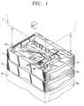
- Fig. 1 shows three paper trays, 1, 3 and 5 stacked vertically upon one another and a printer 7 shown illustratively spaced away from the stack of paper trays 1, 3 and 5.
- Printer 7 may be a laser printer which prints on paper delivered from the paper trays 1, 3 and 5.
- the paper trays 1, 3 and 5 receive drawers 1a, 3a and 5a.
- the drawers 1a, 3a and 5a are pulled out to load paper.
- a drawer 9 is shown in Fig. 2, which is representative of drawers 1a, 3a and 5a except that the depth of drawers 1a, 3a and 5a vary depending on whether they hold 250 or 500 sheets of standard paper.
- Drawer 9 has an adjustable rear paper barrier 11 which is manually adjusted to abut the rear of paper loaded in drawer 9.
- Rear barrier 11 is moved manually by sliding, and is attached to encoded slider 13 which has depressions or holes 15 in coded patterns located corresponding to discrete paper sizes, such as for 8 1/2 by 11 inch coded paper, and A4 paper.
- Slider 13 is held in the side wall 17 of drawer 9 for longitudinal movement with barrier 11.
- Fig. 2 is partially sectioned to show this relationship, as well as holes 15.
- Different codes on slider 13 are defined by vertical columns having one or more holes 15.
- Pivot arms 19 are held stationary in side wall 17 in a vertical column and are located to point somewhat toward the inside of drawer 9. Bent end portions of arms 19 drop into holes 15.
- the number of arms 19 is the same as the maximum number of holes 15 in a vertical column on slider 13, larger numbers being needed to accommodate more information. Where an arm 19 does not find a hole 15, the extreme end of that arm 19 extends past the side wall 17, where it may be readily sensed by a suitable mechanism in the tray 1a, 3a or 5a (preferably simply by a switch which is depressed by the end of each arm 19 not depressed into a hole 15).
- the code columns of holes 15 on slider 13 are selected so that none has a hole 15 in every possible location. Therefore, when drawer 9 is installed in a tray 1a, 3a or 5a, the fact that one arm 19 is sensed establishes the drawer presence. When a nonstandard size paper or other media is installed in drawer 9, then all of the arms 9 are sensed and the presence of nonstandard media is known. Paper presence and the amount of paper is sensed by a rotating element (not shown) resting on the top of paper in drawer 9, the degree of rotation defining the height of the paper in drawer 9. Various techniques for sensing the amount and size of media in drawer 9 are known and virtually all may be employed in accordance with this invention.
- printer 7 When printer 7 is stacked on tray 1, printer 7 has a mating electrical pin connector (not shown), which plugs into socket connector 33. Similarly, printer 7 has a shaft (not shown) which enters locating socket 35.
- trays 1 and 3 have socket connectors and shafts which plug into upper electrical connector (such as 33) and shafts which enter locating sockets (such as 35) respectively of lower trays 3 and 5 respectively.
- the two tray accessory unit 41 in accordance with this invention is shown in Fig. 3, with left cover elements removed to illustrate electrical elements.
- the unit 41 has an upper paper tray 43 permanently fastened to a lower paper tray 45, in any suitable manner such as by bolts. Trays 43 and 45 may be of different media volume (one having height to hold 250 sheets and the other having height to hold 500 sheets). Except for being fastened together and for the electrical logic elements to be described, trays 43 and 45 are the same as trays 1, 3 and 5 and are stacked as are trays 1, 3 and 5. One use for unit 41 would be to replace trays 3 and 5 in the printer system described with respect to Fig. 1.
- Tray 43 has a printed circuit board 47 holding conventional logic circuit elements and their connecting leads, including a microprocessor 49.
- the circuit board 47 with microprocessor 49 is the same overall configuration as a circuit board and microprocessor (not shown) of each of the individual trays 1, 3 and 5.
- Tray 45 has a printed circuit board 51 holding conventional logic circuit elements and their connecting leads. Circuit board 51 is electrically connected to circuit board 47 through a multiline cable 53. Circuit board 51 does not contain a microprocessor. The output of the logic of board 51 is communicated to microprocessor 49 through cable 53.
- the top electrical socket connector 33 is electrically connected to circuit board 47 by a cable 55.
- a second cable 57 is connected from circuit board 47 to the bottom of unit 41, where it has a mating connector 59 which plugs into a connector 33.
- the tray 43 has no mating lower connector 59 and the tray 45 has no upper socket connector.
- unit 41 may be stacked on a further accessory, such as one of the trays 1, 3 and 5; and connector 59 of unit 41 will plug into the socket connector 33 of the lower unit, to form an operative printer system which includes unit 41 and any units so stacked under unit 41.
- trays 43 and 45 transmit motive power through shafts (not shown) and connectors 35 in the same manner as trays 1,3, and 5.
- a control computer 61 in printer 7 on initiation (such as when power is initially turned on) transmits through connector 33 a predetermined initiation command.
- the logic of the first unit to receive that command, such as tray 1 presents an open circuit which blocks that command.
- the microprocessor of tray 1 recognizes the command and reports the status information of paper size, drawer presence and volume back to printer 7 through connector 33.
- the microprocessor of tray 1 might then generate the initiation command and transmit it through the lower connector (such as 59 of Fig. 3) to the next lower unit, 3 in Fig. 1, or to unit 41 when unit 41 replaces trays 3 and 5.
- the printer microprocessor 61 produces the subsequent initiation commands and the microprocessor of each unit activates logic which closes a circuit path to the power connector, such as connector 59 of Fig. 3.
- the first unit receives an initiation command which the lower units do not.
- the first unit transmit information to printer 7 describing the first unit, the next lower unit then receives the initiation command and it transmits information to printer 7 describing that unit. This continues in sequence for all stacked units.
- microprocessor 61 of printer 7 infers that no further accessory unit is in the printer system and normal printing operation is begun under the control of microprocessor 61.
- unit 41 The operation of unit 41 is exceptional in that it reports once identifying itself as a dual tray unit and providing description information specific to each tray.
- All connection to the lower tray 45 could be by cable 53, with the connection to lower connector 59 being from board 51.
- cables 55 and 57 could be a single cable with branching .
- the embodiment described is selected to be the most similar in construction to that of the single trays 1, 3 and 5, to simplify manufacture and speed design.
- microprocessor of this description are the commonly known small electronic data processors, typically formed on a single silicone chip. As such, their cost is significant and this invention avoids the use of at least one microprocessor.
Landscapes
- Engineering & Computer Science (AREA)
- Mechanical Engineering (AREA)
- Physics & Mathematics (AREA)
- General Physics & Mathematics (AREA)
- Sheets, Magazines, And Separation Thereof (AREA)
- Handling Of Cut Paper (AREA)
- Accessory Devices And Overall Control Thereof (AREA)
Applications Claiming Priority (2)
| Application Number | Priority Date | Filing Date | Title |
|---|---|---|---|
| US08/853,775 US5758249A (en) | 1997-05-09 | 1997-05-09 | Status reporting from multiple tray accessory |
| US853775 | 1997-05-09 |
Publications (2)
| Publication Number | Publication Date |
|---|---|
| EP0877336A2 true EP0877336A2 (de) | 1998-11-11 |
| EP0877336A3 EP0877336A3 (de) | 2002-12-11 |
Family
ID=25316864
Family Applications (1)
| Application Number | Title | Priority Date | Filing Date |
|---|---|---|---|
| EP98108379A Withdrawn EP0877336A3 (de) | 1997-05-09 | 1998-05-08 | Statusmeldung von Zusatzeinheiten in einem Drucker |
Country Status (6)
| Country | Link |
|---|---|
| US (1) | US5758249A (de) |
| EP (1) | EP0877336A3 (de) |
| JP (1) | JPH1158896A (de) |
| KR (1) | KR19980086885A (de) |
| CN (1) | CN1139033C (de) |
| TW (1) | TW463032B (de) |
Families Citing this family (26)
| Publication number | Priority date | Publication date | Assignee | Title |
|---|---|---|---|---|
| US5963755A (en) * | 1995-04-17 | 1999-10-05 | Canon Kabushiki Kaisha | Printing apparatus and control device for option equipment connected thereto |
| JPH10129860A (ja) * | 1996-10-31 | 1998-05-19 | Canon Inc | 記録装置 |
| JP3697010B2 (ja) * | 1997-02-26 | 2005-09-21 | キヤノン株式会社 | 電子写真装置のモジュール連結構造 |
| US5884132A (en) * | 1997-10-20 | 1999-03-16 | Eastman Kodak Company | Cabinetry with shape-based indicators |
| US6072585A (en) * | 1997-12-12 | 2000-06-06 | Lexmark International, Inc. | Method and apparatus for managing the power consumption of a printer |
| USD415192S (en) * | 1998-06-18 | 1999-10-12 | Hewlett-Packard Company | Feeder with tray for a document printer |
| US6279899B1 (en) | 1999-09-03 | 2001-08-28 | Lexmark International, Inc. | Substrate sensing mechanism for use in a printer output bin |
| USD463483S1 (en) | 2000-10-10 | 2002-09-24 | Matsushita Graphic Communication Systems, Inc. | Paper feed cassette |
| USD454153S1 (en) | 2000-10-10 | 2002-03-05 | Matsushita Graphic Commication Systems, Inc. | Exclusive base of copying machine |
| JP3843730B2 (ja) * | 2000-11-13 | 2006-11-08 | ブラザー工業株式会社 | 画像形成装置及び記録媒体供給装置 |
| US6688590B2 (en) | 2000-12-08 | 2004-02-10 | Lexmark International, Inc. | Dual tray printer with single drive shaft and dual media picks |
| KR100503457B1 (ko) * | 2003-04-25 | 2005-07-25 | 삼성전자주식회사 | 보조 급지 용지함 제어 장치 및 그 방법 |
| US7292820B2 (en) * | 2003-07-30 | 2007-11-06 | Lexmark International, Inc. | Integrated media input tray including electronics |
| US7014483B2 (en) * | 2004-07-02 | 2006-03-21 | Transact Technologies Incorporated | Methods and apparatus for connecting a host device and a printer |
| JP2006096456A (ja) * | 2004-09-28 | 2006-04-13 | Brother Ind Ltd | 画像形成装置及び増設給紙装置 |
| KR101101830B1 (ko) * | 2005-06-23 | 2012-01-05 | 삼성전자주식회사 | 회로장치 및 그 디바이스제어방법 |
| KR100793347B1 (ko) * | 2006-07-07 | 2008-01-11 | 삼성전자주식회사 | 화상 형성 장치의 카세트 제어 방법 및 그 장치 |
| JP2013210617A (ja) * | 2012-02-28 | 2013-10-10 | Kyocera Document Solutions Inc | シート給送装置及び画像形成装置 |
| US9074869B2 (en) | 2013-12-11 | 2015-07-07 | Faro Technologies, Inc. | Method for measuring 3D coordinates of a spherically mounted retroreflector from multiple stations |
| US9329028B2 (en) * | 2013-12-11 | 2016-05-03 | Faro Technologies, Inc. | Spherically mounted retroreflector having an embedded temperature sensor and socket |
| US9347767B2 (en) | 2013-12-11 | 2016-05-24 | Faro Technologies, Inc. | Spherically mounted retroreflector and method to minimize measurement error |
| US9423492B2 (en) | 2013-12-11 | 2016-08-23 | Faro Technologies, Inc. | Method for finding a home reference distance using a spherically mounted retroreflector |
| US9121689B2 (en) | 2013-12-11 | 2015-09-01 | Faro Technologies, Inc. | Method for correcting a spherically mounted retroreflector when resetting a distance meter |
| US9239238B2 (en) | 2013-12-11 | 2016-01-19 | Faro Technologies, Inc. | Method for correcting a 3D measurement of a spherically mounted retroreflector on a nest |
| EP3509850A4 (de) * | 2016-09-09 | 2020-05-06 | Hewlett-Packard Development Company, L.P. | Druckerschachtleiterplattenanordnung |
| CN108726215A (zh) * | 2018-09-07 | 2018-11-02 | 天津光电通信技术有限公司 | 一种图像形成装置的打印介质扩容框架及图像形成装置 |
Family Cites Families (23)
| Publication number | Priority date | Publication date | Assignee | Title |
|---|---|---|---|---|
| US4099150A (en) * | 1976-06-01 | 1978-07-04 | Eastman Kodak Company | Apparatus for producing duplex collated copies |
| DK151414C (da) * | 1983-11-03 | 1988-05-16 | Mercante Int As | Elektrofotografisk informationsskriver med xerografisk reproduktionssystem |
| US4733310A (en) * | 1986-05-23 | 1988-03-22 | Ziyad, Inc. | Paper sheet and envelope feeder apparatus |
| US4966356A (en) * | 1987-09-30 | 1990-10-30 | Fujitsu Limited | Apparatus for selectively feeding cut sheets in a recording machine |
| US4970544A (en) * | 1987-11-26 | 1990-11-13 | Fuji Xerox Co., Ltd. | Paper tray control system |
| EP0370484B1 (de) * | 1988-11-22 | 1994-07-27 | Canon Kabushiki Kaisha | Bogenzuführvorrichtung |
| JPH0829845B2 (ja) * | 1989-04-13 | 1996-03-27 | シャープ株式会社 | 電子写真装置 |
| JPH0745291B2 (ja) * | 1989-05-15 | 1995-05-17 | シャープ株式会社 | 給紙装置 |
| JPH0480159A (ja) * | 1990-07-23 | 1992-03-13 | Toshiba Corp | 給紙装置 |
| JPH04209138A (ja) * | 1990-11-30 | 1992-07-30 | Toshiba Corp | 給紙カセット並びにこの給紙カセットを用いた画像形成装置 |
| US5368285A (en) * | 1991-02-28 | 1994-11-29 | Canon Kabushiki Kaisha | Automatic sheet feeding apparatus |
| JP2964676B2 (ja) * | 1991-03-27 | 1999-10-18 | ブラザー工業株式会社 | カセット式給紙装置 |
| US5191382A (en) * | 1991-04-22 | 1993-03-02 | Canon Kabushiki Kaisha | Image forming system |
| JPH0566622A (ja) * | 1991-09-05 | 1993-03-19 | Toshiba Corp | 画像形成装置 |
| JPH0592824A (ja) * | 1991-09-30 | 1993-04-16 | Hitachi Ltd | 情報印刷システム |
| JP2759011B2 (ja) * | 1991-10-28 | 1998-05-28 | 株式会社東芝 | 画像形成装置 |
| JP3171472B2 (ja) * | 1992-01-10 | 2001-05-28 | 株式会社リコー | 自動給紙型記録装置 |
| JPH0627774A (ja) * | 1992-06-29 | 1994-02-04 | Ricoh Co Ltd | 用紙選択機能付き画像形成装置 |
| JP3177052B2 (ja) * | 1993-03-22 | 2001-06-18 | 株式会社東芝 | 画像形成装置 |
| JPH07137853A (ja) * | 1993-11-12 | 1995-05-30 | Minolta Co Ltd | 画像形成装置 |
| US5502555A (en) * | 1994-07-11 | 1996-03-26 | Xerox Corporation | Printing system having an image characteristics automatic method and apparatus for copy sheet reselection |
| JP3230948B2 (ja) * | 1994-10-03 | 2001-11-19 | キヤノン株式会社 | 画像形成装置 |
| US5699091A (en) * | 1994-12-22 | 1997-12-16 | Hewlett-Packard Company | Replaceable part with integral memory for usage, calibration and other data |
-
1997
- 1997-05-09 US US08/853,775 patent/US5758249A/en not_active Expired - Lifetime
-
1998
- 1998-05-08 CN CNB981078966A patent/CN1139033C/zh not_active Expired - Fee Related
- 1998-05-08 EP EP98108379A patent/EP0877336A3/de not_active Withdrawn
- 1998-05-08 KR KR1019980016491A patent/KR19980086885A/ko not_active Ceased
- 1998-05-11 JP JP10167648A patent/JPH1158896A/ja not_active Withdrawn
- 1998-07-18 TW TW087107152A patent/TW463032B/zh not_active IP Right Cessation
Also Published As
| Publication number | Publication date |
|---|---|
| CN1139033C (zh) | 2004-02-18 |
| JPH1158896A (ja) | 1999-03-02 |
| KR19980086885A (ko) | 1998-12-05 |
| CN1199201A (zh) | 1998-11-18 |
| TW463032B (en) | 2001-11-11 |
| EP0877336A3 (de) | 2002-12-11 |
| US5758249A (en) | 1998-05-26 |
Similar Documents
| Publication | Publication Date | Title |
|---|---|---|
| US5758249A (en) | Status reporting from multiple tray accessory | |
| US5865546A (en) | Modular keyboard for use in a computer system | |
| US6586849B2 (en) | Electrical power strip for use with a computer and associated peripheral devices | |
| JP3357048B2 (ja) | ホストプロセサにポータブルデータキャリアをインターフェイスする方法及びカプラ | |
| US6850417B2 (en) | Integrated expansion card slot status indicator and power actuator | |
| EP1759363A1 (de) | Kassensysteme mit auswechselbaren schnittstellenmodulen und offenem zustand mehrfacher kassenladen | |
| US4745404A (en) | Display device for planning purposes | |
| US5142626A (en) | Personal computer with removable media identification | |
| EP0467595A2 (de) | Personalcomputer mit Verbinderanordnung, welcher eine Verriegelungsvorrichtung aufweist | |
| US5440693A (en) | Personal computer with drive identification | |
| US8677040B2 (en) | Host-peripheral adaptor | |
| US20040029416A1 (en) | Portable universal coupler for computer facility | |
| EP0467596B1 (de) | Entnehmbare Datenspeichereinrichtung und Werkzeug zur Entnahme dieser Speichereinrichtung aus einem Bürorechner | |
| JP2687911B2 (ja) | プリント配線基板の誤挿入防止機構 | |
| US6805293B2 (en) | Data collection system | |
| JP2628477B2 (ja) | ゲーム装置及びその接続装置 | |
| JPH0726756Y2 (ja) | ディジタル制御装置 | |
| CN219676726U (zh) | 阅读装置 | |
| US7005877B2 (en) | Burn-in adapter | |
| EP1076879B1 (de) | Einheit die eine lese-/schreibe-vorrichtung enthält | |
| KR101955999B1 (ko) | 점자 입력기 | |
| KR960003415B1 (ko) | 착탈식 매체 직접 액세스 저장 장치(dasd) 및 그에 삽입된 매체 형태를 식별하는 퍼스널 컴퓨터 및 퍼스널 컴퓨터 시스템 | |
| US6239714B1 (en) | Controller for use in an interconnection system | |
| JPH0755012Y2 (ja) | アドレス設定構造 | |
| EP0251235B1 (de) | Dienstmodul für Bedienerschnittstelle |
Legal Events
| Date | Code | Title | Description |
|---|---|---|---|
| PUAI | Public reference made under article 153(3) epc to a published international application that has entered the european phase |
Free format text: ORIGINAL CODE: 0009012 |
|
| AK | Designated contracting states |
Kind code of ref document: A2 Designated state(s): AT BE CH CY DE DK ES FI FR GB GR IE IT LI LU MC NL PT SE |
|
| AX | Request for extension of the european patent |
Free format text: AL;LT;LV;MK;RO;SI |
|
| PUAL | Search report despatched |
Free format text: ORIGINAL CODE: 0009013 |
|
| AK | Designated contracting states |
Kind code of ref document: A3 Designated state(s): AT BE CH CY DE DK ES FI FR GB GR IE IT LI LU MC NL PT SE |
|
| AX | Request for extension of the european patent |
Free format text: AL;LT;LV;MK;RO;SI |
|
| RIC1 | Information provided on ipc code assigned before grant |
Free format text: 7G 06K 15/00 A, 7G 06K 15/16 B, 7B 41J 29/00 B, 7G 03G 15/00 B |
|
| AKX | Designation fees paid |
Designated state(s): DE FR GB |
|
| STAA | Information on the status of an ep patent application or granted ep patent |
Free format text: STATUS: THE APPLICATION IS DEEMED TO BE WITHDRAWN |
|
| 18D | Application deemed to be withdrawn |
Effective date: 20030612 |