EP0875952B1 - Dünnschicht Feststoff Lithiumzellen und Verfahren zur Herstellung - Google Patents
Dünnschicht Feststoff Lithiumzellen und Verfahren zur Herstellung Download PDFInfo
- Publication number
- EP0875952B1 EP0875952B1 EP98201306A EP98201306A EP0875952B1 EP 0875952 B1 EP0875952 B1 EP 0875952B1 EP 98201306 A EP98201306 A EP 98201306A EP 98201306 A EP98201306 A EP 98201306A EP 0875952 B1 EP0875952 B1 EP 0875952B1
- Authority
- EP
- European Patent Office
- Prior art keywords
- process according
- cutting
- lithium
- cathode
- cells
- Prior art date
- Legal status (The legal status is an assumption and is not a legal conclusion. Google has not performed a legal analysis and makes no representation as to the accuracy of the status listed.)
- Expired - Lifetime
Links
Images


Classifications
-
- H—ELECTRICITY
- H01—ELECTRIC ELEMENTS
- H01M—PROCESSES OR MEANS, e.g. BATTERIES, FOR THE DIRECT CONVERSION OF CHEMICAL ENERGY INTO ELECTRICAL ENERGY
- H01M10/00—Secondary cells; Manufacture thereof
- H01M10/05—Accumulators with non-aqueous electrolyte
- H01M10/052—Li-accumulators
-
- H—ELECTRICITY
- H01—ELECTRIC ELEMENTS
- H01M—PROCESSES OR MEANS, e.g. BATTERIES, FOR THE DIRECT CONVERSION OF CHEMICAL ENERGY INTO ELECTRICAL ENERGY
- H01M10/00—Secondary cells; Manufacture thereof
- H01M10/04—Construction or manufacture in general
- H01M10/0436—Small-sized flat cells or batteries for portable equipment
-
- H—ELECTRICITY
- H01—ELECTRIC ELEMENTS
- H01M—PROCESSES OR MEANS, e.g. BATTERIES, FOR THE DIRECT CONVERSION OF CHEMICAL ENERGY INTO ELECTRICAL ENERGY
- H01M10/00—Secondary cells; Manufacture thereof
- H01M10/05—Accumulators with non-aqueous electrolyte
- H01M10/056—Accumulators with non-aqueous electrolyte characterised by the materials used as electrolytes, e.g. mixed inorganic/organic electrolytes
- H01M10/0564—Accumulators with non-aqueous electrolyte characterised by the materials used as electrolytes, e.g. mixed inorganic/organic electrolytes the electrolyte being constituted of organic materials only
- H01M10/0565—Polymeric materials, e.g. gel-type or solid-type
-
- H—ELECTRICITY
- H01—ELECTRIC ELEMENTS
- H01M—PROCESSES OR MEANS, e.g. BATTERIES, FOR THE DIRECT CONVERSION OF CHEMICAL ENERGY INTO ELECTRICAL ENERGY
- H01M4/00—Electrodes
- H01M4/02—Electrodes composed of, or comprising, active material
- H01M4/04—Processes of manufacture in general
-
- H—ELECTRICITY
- H01—ELECTRIC ELEMENTS
- H01M—PROCESSES OR MEANS, e.g. BATTERIES, FOR THE DIRECT CONVERSION OF CHEMICAL ENERGY INTO ELECTRICAL ENERGY
- H01M6/00—Primary cells; Manufacture thereof
- H01M6/14—Cells with non-aqueous electrolyte
- H01M6/18—Cells with non-aqueous electrolyte with solid electrolyte
- H01M6/188—Processes of manufacture
-
- H—ELECTRICITY
- H01—ELECTRIC ELEMENTS
- H01M—PROCESSES OR MEANS, e.g. BATTERIES, FOR THE DIRECT CONVERSION OF CHEMICAL ENERGY INTO ELECTRICAL ENERGY
- H01M6/00—Primary cells; Manufacture thereof
- H01M6/40—Printed batteries, e.g. thin film batteries
-
- Y—GENERAL TAGGING OF NEW TECHNOLOGICAL DEVELOPMENTS; GENERAL TAGGING OF CROSS-SECTIONAL TECHNOLOGIES SPANNING OVER SEVERAL SECTIONS OF THE IPC; TECHNICAL SUBJECTS COVERED BY FORMER USPC CROSS-REFERENCE ART COLLECTIONS [XRACs] AND DIGESTS
- Y02—TECHNOLOGIES OR APPLICATIONS FOR MITIGATION OR ADAPTATION AGAINST CLIMATE CHANGE
- Y02E—REDUCTION OF GREENHOUSE GAS [GHG] EMISSIONS, RELATED TO ENERGY GENERATION, TRANSMISSION OR DISTRIBUTION
- Y02E60/00—Enabling technologies; Technologies with a potential or indirect contribution to GHG emissions mitigation
- Y02E60/10—Energy storage using batteries
-
- Y—GENERAL TAGGING OF NEW TECHNOLOGICAL DEVELOPMENTS; GENERAL TAGGING OF CROSS-SECTIONAL TECHNOLOGIES SPANNING OVER SEVERAL SECTIONS OF THE IPC; TECHNICAL SUBJECTS COVERED BY FORMER USPC CROSS-REFERENCE ART COLLECTIONS [XRACs] AND DIGESTS
- Y02—TECHNOLOGIES OR APPLICATIONS FOR MITIGATION OR ADAPTATION AGAINST CLIMATE CHANGE
- Y02P—CLIMATE CHANGE MITIGATION TECHNOLOGIES IN THE PRODUCTION OR PROCESSING OF GOODS
- Y02P70/00—Climate change mitigation technologies in the production process for final industrial or consumer products
- Y02P70/50—Manufacturing or production processes characterised by the final manufactured product
-
- Y—GENERAL TAGGING OF NEW TECHNOLOGICAL DEVELOPMENTS; GENERAL TAGGING OF CROSS-SECTIONAL TECHNOLOGIES SPANNING OVER SEVERAL SECTIONS OF THE IPC; TECHNICAL SUBJECTS COVERED BY FORMER USPC CROSS-REFERENCE ART COLLECTIONS [XRACs] AND DIGESTS
- Y10—TECHNICAL SUBJECTS COVERED BY FORMER USPC
- Y10T—TECHNICAL SUBJECTS COVERED BY FORMER US CLASSIFICATION
- Y10T29/00—Metal working
- Y10T29/49—Method of mechanical manufacture
- Y10T29/49002—Electrical device making
- Y10T29/49108—Electric battery cell making
- Y10T29/49112—Electric battery cell making including laminating of indefinite length material
Definitions
- the present invention relates to ultra-thin lithium batteries and to the solid state and their manufacturing process.
- the invention relates to a method for manufacturing thin batteries with polymer electrolyte with lithium or sodium anode, as well as batteries obtained by this process. More particularly, the invention relates to the preparation of polymer electrolyte batteries from a mother-roll battery that are cut open mechanically.
- this invention relates to the use of a large surface laminated stack prepared by continuous processes whose design is particularly favorable to the production of smaller elements by simple direct cutting laminate as well as the manufacturing process of small ultra-thin batteries by mechanical cutting.
- the electrochemical cells or generators whether rechargeable or not, all consist of an anode which may consist of a metal such as lithium, of a cathode which it consists of an insertion compound, inserting, in a reversible manner or not, the alkaline ions, such as vanadium oxide or manganese dioxide, a mechanical separator placed between the electrodes, and an electrolytic component.
- electrolytic component is meant any material included in the generator used for ion transport, with the exception of the active materials of the electrode, in which the Li + ions can move, both at the level of the separator and in the composite electrode.
- the electrolytic component ensures the transport of ionic species throughout the generator either from one electrode to another and inside the composite electrode itself.
- the functions of separator and electrolytic component are generally combined in one and the same material.
- Small lithium batteries, rechargeable or not, such as batteries buttons and flat batteries are usually made by developing and the cutting of the individual components which are then assembled.
- the batteries or their components are developed in the form of stacks or elements multiples of predetermined dimension which are then cut out from electrochemically inactive zones provided for this purpose so as to allow local cutting without damage to the device electrochemical. Examples of batteries using this manufacturing process are described in U.S. Patent Nos. 4,177,330, 5,378,557 and 5,547,780.
- the active electrodes metallic lithium and composite cathode
- the material packaging which then serves as a protective barrier and collector of current; often these electrodes are produced directly on the material packaging by coating or pressing.
- barrier and collector on the same material, then allows optimize the weight and volume of the complete stack.
- the subject of the invention is the manufacture of batteries with polymer electrolyte and with lithium or sodium anode which involves a surprising effect self-healing of the anode, which facilitates cutting into small elements with little or no rejection rate.
- the invention also relates to a method for cutting a stack. mother laminate which does not leave weak points electrochemically such as demonstrated by the electrochemical cycling of batteries produced according to the invention.
- Another subject of the invention is a method for manufacturing batteries which, non-limitingly, involves chemical dissolution or electrochemical lithium or metallic sodium when contacted with the cathode material in order to rationalize the self-healing mechanism.
- the invention also aims to demonstrate by examples that self-healing mechanism exists which tends to absorb the short circuit often caused by mechanical cutting, even in the absence of air and water.
- the object of the invention is also to demonstrate by tests of cycling that the phenomenon of self-healing tends to eliminate lithium from cutting areas.
- Another object of the invention lies in the design of a method of simplified manufacturing based on the sharp cutting of a large surface stack prepared by continuous processes, without having to presume in advance of the shape or size of the pile to be produced.
- the invention relates to a method for manufacturing electrolyte batteries.
- polymer gelled or not and with anode based on lithium or sodium from of a large surface laminated mother cell comprising an anode strip with lithium or sodium base, a polymer electrolyte and a cathode in the form of a thin film, characterized in that the cathode has the property of dissolve the lithium or the sodium, and a mechanical cutting is carried out vivid of the mother battery making it possible to bring into play a phenomenon of self-healing resulting in chemical dissolution in the cathode of everything lithium or sodium having been in contact with the cathode during the cutting.
- the anode is based on metallic lithium.
- the polymer electrolyte conducts alkaline ions of the anode and that it also acts as a separator between the anode and the cathode.
- the mother battery comprises a composite cathode made of a compound reducible to lithium or sodium, an electronic conduction additive and an electrolyte binder polymer.
- an electronic conductive coating can be provided. thin on the external face of the anode and possibly of the cathode, the conductive material is chemically and electrochemically inert towards electrode material and is also used to make contacts permanent electrics on the external faces of the cut batteries.
- the thickness of the conductive coating of the anode and possibly of the cathode is preferably less than 5 micrometers ( ⁇ m) so as to minimize weight and volume and retain the flexibility of the entire the thin stack.
- the conductive coating is for example a thin strip metallic based on nickel or iron as described in U.S. Patent No. 5,423,974. It can also consist of a composite comprising a binder inert polymer and a dispersed and inert electronic conductive filler vis-à-vis the electrode material.
- the conductive load this the latter may be an inert conductive lithium powder comprising, non-limiting way, nitrides, carbides and metal borides, in the case of the anode or it may also include carbon in the case of the conductive coating of the cathode.
- the inert polymeric binder is not ionic conductor and may include, without limitation, patterns ethylene and propylene monomers, for example the polymeric binder is chosen from polyethylene, polypropylene or ethylene copolymer propylene diene (EPDM).
- the inert polymeric binder can be prepared from easy to crosslinkable prepolymers and / or functional monomers enforce. As a non-limiting example of groupings functional we find: acrylates, methacrylates, allyles, vinyls or a combination thereof.
- the inert polymeric binder may also comprise fluorinated units, the vinyldiene fluoride (PVDF) or the copolymer of vinyldiene fluoride - co-hexafluoropropene (PVDF-HFP).
- PVDF vinyldiene fluoride
- PVDF-HFP copolymer of vinyldiene fluoride - co-hexafluoropropene
- the inert polymeric binder may be an adhesive, in particular a thermo-adhesive, so as to facilitate the positioning of the batteries and the quality of the electrical contacts.
- the composite conductive coating should have a surface resistance varying between 0.1 and 1000 ⁇ / cm 2 , preferably between 1 and 300 ⁇ / cm 2 , so as to limit a short-circuit current during cutting, for reasons of maintenance. of the state of charge and for the safety of cutting operations.
- the mother battery is obtained from films of anode, cathode and polymer electrolyte, which are assembled by coating and film transfer processes, these films being adherent to each other. If necessary, crosslinking steps are used before or after coating or transfer of films.
- the thin batteries can be stacked in parallel or in series, or they can be stacked after zigzag folding. Can also put in a package consisting of a single box, thin batteries individually or stacked in parallel or in series.
- the laminated mother battery has a peelable support film on at least one of its faces so to facilitate its production and handling.
- This peelable backing film is preferably and without limitation made of polypropylene or polyethylene, and it is removed just before the battery cutting operation.
- the polymer electrolyte in the separator and, if necessary, the electrode is in particular made up of molecular mass greater than 50,000 so as to obtain films which can be handled and transferred by continuous rolling. You can also use a gelled polymer electrolyte so as to optimize the ionic conductivity at room temperature.
- Through gelled polymer means a polymer matrix capable of incorporating a polar aprotic organic solvent to form a gel.
- the polymer electrolyte consists of a polymer matrix and the latter is made conductive by the addition of minus a polar aprotic solvent and an alkali metal salt soluble in the electrolyte.
- This addition of a polar aprotic liquid solvent can be do after the cutting operation so as to minimize the short-circuit current when cutting. It is the same for the alkaline salt that we add preferably after the cutting operation so as to minimize the current short circuit.
- Adding polar aprotic solvents or salt or both after battery assembly can be facilitated by the use of at least one permeable composite conductive coating to facilitate introduction of these.
- the cutting operation can be done mechanically so known in the art by means of punching tools (blanking), crushing (score cutting) or shear (score cutting) or even cutting is carried out with a tool consisting at least in part of an insulating material of so as to minimize the short circuit during cutting. Cutting can also be carried out in the presence of an inert or reactive lithium lubricant. During or after the cutting operation, a chemical reaction can be carried out lithium or sodium from the cut edge to remove more quickly short circuit and neutralize electrochemical activity lateral. This operation facilitates the phenomenon of self-healing mentioned in this invention.
- the chemical reaction takes place normally in the presence of reagents capable of oxidizing the lithium of the edge, and which are liquids or gases, especially air, capable of forming a composed of electrically insulating lithium, insoluble in the polymer electrolyte and can also consolidate the edge.
- reagents capable of oxidizing the lithium of the edge and which are liquids or gases, especially air, capable of forming a composed of electrically insulating lithium, insoluble in the polymer electrolyte and can also consolidate the edge.
- the compound formed is for example based on carbonates, oxyanions, oxides, chalcogenides, derivatives fluorine or alcoholates.
- edges of the stack it is possible to consolidate the edges of the stack, to prevent any undesirable deformation, by a reaction of edge polymerization during cutting.
- the reaction being catalyzed or initiated by freshly cut alkali metal.
- the invention also relates to a thin battery with polymer electrolyte constituted by the superposition of a cathode in the form of a thin film, of a polymer electrolyte as well as an anode strip based on lithium or sodium, characterized in that it is obtained by cutting said overlapping so that its ends after cutting are uniformly sliced, that optionally we find at the edge a thin film obtained by the reaction of a reactive lubricant during cutting which consolidates and electrically isolates the edge, and finally said pile retains substantially the same voltage when produced as that of a mother battery used for its production by cutting.
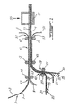
- FIGURE 1 With particular reference to FIGURE 1, given as non-limiting, it will be seen that the production of a laminated stack of large surface 1 is carried out by a continuous process as illustrated.
- the laminating device illustrated With a polypropylene film 3 of a thickness of approximately 20 ⁇ m previously treated by metallization / plating of nickel 5 in a manner known in the art (U.S. Patent No. 5,423,974) and a thickness less than about 5 ⁇ m, so as to coat the film with polypropylene 3 with a peelable layer of nickel 7 with a thickness of 2 ⁇ m.
- the rolling device is supplied with a film 9 of a thickness between about 10 and 30 ⁇ m mainly comprising lithium metallic and intended to constitute the anode 11 of the laminated mother cell of large area 1.
- a second rolling mill 19 is also fed. of the rolling device with another polypropylene film 21 which is coated in 23 in a known manner, with a polymer electrolyte film 25, of which the thickness can vary between around 5 and 30 ⁇ m, before introducing it into the rolling mill 19 between cylinders 27 and 29.
- a polymer electrolyte film 25 of which the thickness can vary between around 5 and 30 ⁇ m, before introducing it into the rolling mill 19 between cylinders 27 and 29.
- a third polypropylene film 31 is simultaneously fed at the rolling mill 19, but beforehand it is coated with a layer of nickel 33 with a thickness of less than about 5 ⁇ m, by a step of metallization / plating well known to those skilled in the art, in 35. Before its introduction into the rolling mill 19 and after having been coated with nickel thickness of 2 ⁇ m, the nickel coated polypropylene film is coated in 37 a cathode film 39. The polypropylene film 31, coated with nickel 33 and coated with cathode 39 is then introduced into the rolling mill 19 at the same time while the polypropylene film 21 coated with electrolyte 25.
- Ni ° / Li ° laminate at 13 and that made of polypropylene laminate - electrolyte - cathode are introduced into the rolling mill 41 consisting of cylinders 43, 45 and 47, 49, but beforehand we had peeled the film polypropylene 21 in 42.
- the support film is peeled 3 in 51, and the support film 31 in 53 and a laminated mother stack of large surface whose anode consists mainly of lithium metallic, the separator of a gelled or not gelled polymer electrolyte and the cathode of a composite material bound by a gelled polymer electrolyte or no; the anode is covered with a thin conductive coating inert to lithium such as, for example, metallic nickel; the composite cathode also has an inert conductive coating.
- the coatings external conductors are chosen thin, preferably less than 5 ⁇ m, so as to make them negligible compared to the thickness of the sum of the other components of the laminate and so as to keep the assembly flexible and easy to manipulate.
- These conductive coatings are preferably inert to the electrodes with which they are in contact for ensure the quality of electrical contacts.
- inert conductive coating we mean materials that are chemically and electrochemically stable with the active material of the corresponding electrode. In a way optional, these coatings can be more or less adherent so to facilitate the positioning of individual or multiple stacks cut when assembled into a complete generator.
- the different components of the laminated stack are welded together but the assembly retains a some flexibility due to the plastic nature of lithium, electrolyte polymer and thin conductive coatings. Note that the peeling operations indicated in FIGURE 1 are effective before the cutting and placing in the laminated stack.
- the live cutting of the mother roll 1 is carried out by means mechanical, schematically illustrated in 55, so as to obtain batteries of smaller area 57.
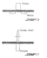
- FIGURES 2 (a), 2 (b) and 2 (c) illustrate the effect of cutting on the edges of the stack which become inaccessible for taking side contacts. Only the external faces are then accessible for the making contact.
- a thin inert conductive coating is used which ensures the quality of the electrical contact and physically isolates the material other batteries or packaging material. So no restrictive, two types of coatings are illustrated in FIGURES 2 (a), 2 (b) and 2 (c).
- a thin metallic coating in this case a 2 ⁇ m nickel thick, and two examples of composite coatings; one consisting of carbon and an inert and non-conductive binder stable in oxidation such as EPDM, PVDF or PVDF-HFP and used at the cathode; the other constituted a metallic conductive boron nitride powder and a stable binder reduction such as EPDM and used at the anode.
- Various compounds inert to lithium and conductors can satisfy these two criteria, in particular, for example, carbides, nitrides and metal borides.
- compounds inert to lithium means materials that are chemically and electrochemically stable against lithium.
- the lateral conductivity of the positive composite and its conductive composite coating so as to limit the short-circuit current temporary cutting, especially in the main laminate surface in order to preserve the state of charge and for safety reasons when the batteries thus cut are optimized for high powers of discharge.
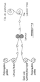
- FIGURES 3 (a), 3 (b) and 3 (c) illustrate respectively assembly when required of the individual stacks in parallel 59, in a zigzag obtained by folding after cutting, or in series, by stacking the stacks, individual 61 or connected in parallel 63 in order to increase the voltage.
- the conductive coatings of the electrodes ensure electrical contacts between units, as shown, for example, in FIGURES 3 (a), 3 (b) and 3 (c).
- Single casing of batteries or sets of batteries series / parallel is made possible by the fact that all the components are in the solid state or without excess solvent, for gelled systems, which avoids the effects of local corrosion, especially for series mounting.
- Sealing of the electrochemical assembly and packaging materials is done using metallic barrier materials as needed collector of the entire electrochemical device. In a way optional, we will take advantage of the adhesion of the conductive coatings of the electrodes to ensure the positioning of the battery or batteries in the housing.
- FIGURES 4 to 9 we will see more particularly in FIGURE 4, how to make a conductive nickel coating adhered to a thin strip of lithium, the whole being obtained by lamination of a strip of lithium supported on plastic as described in U.S. Patent Nos. 5,423,974 and 5,521,028 with a thin nickel strip of 2 ⁇ m supported on a peelable plastic support.
- FIGURE 6 How to cut small area stacks from the stack laminated using a cookie cutter is illustrated in FIGURE 6.
- FIGURE 7 How to Cut Stacks into Strips from the Stack laminated using a rotary knife is illustrated in FIGURE 7.
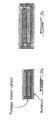
- FIGURE 8 Examples of battery sizes cut on the one hand wins beep or on the other hand with a rotary knife from the mother roll are illustrated in FIGURE 8.
- FIGURES 8 and 9 How to stack single or zigzag stacks in series when we want to develop an effective surface greater than that of the pile wrapped and a multiple voltage of a unit cell is shown in FIGURES 8 and 9.
- FIGURE 9 Examples of packaged unit voltage and voltage batteries multiple are illustrated in FIGURE 9.
- the active material of the cathode can be chosen from cobalt oxide, nickel oxide, nickel cobalt oxide, nickel oxide cobalt aluminum, manganese oxide (LiMn 2 O 4 ) or their analogues for so-called 4V cathodes or also among cathodes of less than 4V such as phosphates or other polyanions of transition metals such as LiFePO 4 , Nasicons structures also including V 2 O 5 , LiV 3 O 8 and MnO 2 , chalcogenides, oxocarbonates such as rhodizonate and halides such as monofluorinated carbons (CF) n .
- the nature of the active material at the cathode is not a limitation of the present invention.
- the electrolytic component can consist of either a ethylene oxide copolymer as described in U.S. Patents Nos. 4,578,326 and 4,758,483 in which at least one alkaline salt is dissolved and which may or may not contain polar aprotic solvent (s), or a gel formed polymers poorly solvating lithium salts or poorly conductive intrinsic in the presence of salts but comprising heteroatoms such as fluorine or polar groups such as nitriles, sulfonates, fluoromethanes, which make them miscible with one or more solvents polar aprotic organic. The latter then give the gel solvating properties of lithium salts so as to give them a role of electrolytic component.
- a ethylene oxide copolymer as described in U.S. Patents Nos. 4,578,326 and 4,758,483 in which at least one alkaline salt is dissolved and which may or may not contain polar aprotic solvent (s), or a gel formed polymers poorly solvating
- the main poorly solvating polymers can be, by way of nonlimiting example, the PVDFs or their copolymers, the polyacrylonitriles and polyelectrolytes comprising groups sulfonates or fluorosulfonates or their equivalents.
- the nature of the electrolytic component is not a limitation of the present invention.
- the cathode may also contain an inert binder facing the material electrode and polar aprotic solvent such as for example not limitative, EPDM.
- polar aprotic solvent such as for example not limitative, EPDM.
- the nature of the cathode binder is not a limitation of the present invention.
- the active material of the anode can be chosen from lithium metal, metallic sodium or an alloy thereof.
- alloy is meant a mixture containing a majority fraction of these alkali metals with one or more other components so that, when cutting, the chemical or electrochemical reaction of the alkali metal with the cathode either sufficient to allow self-healing.
- the exact composition of the lithium or sodium anode is not a limitation of this invention.
- the alkaline salt (s) may be lithium, sodium, potassium or other salts such as, for example, the salts based on lithium trifluoromethanesulfonimide described in US Pat. No. 4,505,997, the lithium salts derived from bisperhaloacyl or sulfonylimide crosslinkable or not described in US Patent No. 4,818,644 and in PCT WO92 / 02966, LiPF 6 , LiBF 4 , LiSO 3 CF 3 , LiClO 4 , LiSCN, NaSCN, NaClO 4 , KSCN and KClO 4 , etc.
- the nature of the salt is not a limitation of the present invention.
- the polar aprotic solvent (s) can be chosen, for example, from propylene carbonate, ethylene carbonate, ethyl methyl carbonate, dimethyl carbonate, diethyl carbonate, tetrahydrofuran, 2 -methyltetrahy drofuran, 1,3-dioxolane, 2,2-dimethyl-1,3-dioxolane, ⁇ -butyrolactone, butylene carbonate, sulfolane, 3-methylsulfolane, ter-bytyl-ether, 1,2-dimethoxyethane, 1,2-diethoxyethane, bis (methoxyethyl) ether, 1,2-ethoxymethoxyethane, terbutylmethylether, glymes and sulfonamides of formula: R 1 R 2 N-SO 2 -NR 3 R 4 , in which R 1 , R 2 , R 3 and R 4 are alkyls comprising
- the laminate includes the following: Ni ° (2 ⁇ m) / Li ° (24 ⁇ m) / Polymer electrolyte (30 ⁇ m) / Composite cathode (45 ⁇ m) / A1 (13 ⁇ m).
- the starting laminate is obtained by continuously coating the cathode on its collector and the electrolyte on a peelable support followed by a hot transfer of the electrolyte on the cathode and peeling of the temporary support; the lithium anode is then transferred with its nickel collector as obtained in FIGURE 4.
- the composite cathode comprises vanadium oxide, carbon black and the polymer electrolyte as a binder.
- the polymer electrolyte which also serves as a separator consists of a copolymer of ethylene oxide in which a lithium salt, (CF 3 SO 2 ) 2 NLi, is dissolved in an O / Li ratio of 30 / 1.
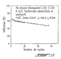
- the behavior in cycling is identical in all points to the behavior in cycling of the starting laminate not cut to the raw when represented proportionally by unit of surface. Only a self-healing phenomenon resulting from an electrochemical dissolution of lithium when brought into contact with the positive electrode explains this result.
- Number of the battery cut under an inert atmosphere Battery voltage after cutting (volts) Battery voltage 1 hour after cutting (volts) 1 3.156 3,410 2 3.202 3.341 3 3.405 3,433 4 0.001 3,016 5 3, 407 3,445 6 3.109 3.331 7 3.387 3.405 8 3,201 3,295 9 0.003 3.105 10 2.797 3.204 11 3.388 3,424 12 3.316 3,410 laminated mother 2,697 3.322
- Example 1 is reproduced, this time replacing the cathode with a second lithium film.
- the laminate thus produced comprises the following elements: Ni ° (2 ⁇ m) / Li ° (24 ⁇ m) / Polymer electrolyte (20 ⁇ m) / Li ° (24 ⁇ m) / Ni ° (2 ⁇ m)
- an impedance measurement shows an interface resistance of 30 ⁇ / cm 2 for the laminated mother stack.
- five stacks of circular shape are taken in a glove box under an argon atmosphere using a cookie cutter.
- a measurement of the impedance of each of these batteries as soon as cutting shows that the battery is short-circuited.
- a second impedance measurement is carried out, the five batteries are still in short circuit demonstrating that the battery cannot self-heal without a reaction of lithium with the active component of the cathode.
- the absence of a lithium reagent does not allow healing at the edge.
- a pile is then treated with a solution of ethyl alcohol to heal the bone. After this treatment, an impedance measurement is made showing that the short circuit is eliminated, the stack then has an impedance similar to that obtained for the laminated mother stack.
- the laminate includes the following: Ni ° (2 ⁇ m) / Li ° (24 ⁇ m) / Polymer electrolyte (15 ⁇ m) / Composite cathode (40 ⁇ m) / A1 (13 ⁇ m).
- the composite cathode includes vanadium oxide, carbon black and polymer electrolyte as a binder.
- the polymer electrolyte which also serves as a separator consists of a copolymer of ethylene oxide in which a lithium salt, (CF 3 SO 2 ) 2 NLi, is dissolved in an O / Li ratio of 30 / 1.
- the US copolymers patents Nos 4,578,326 and 4,758,483 describe non-limiting examples of copolymers which can be used for the process of the invention. These copolymers can be crosslinked if necessary by means known to those skilled in the art.
- Example 3 is reproduced in an anhydrous chamber using this time a gelled polymer electrolyte obtained by beam irradiation electron, EB, at a dose of 5 Mrad.
- the electrolyte is composed by volume of 50% glycerol-tri [poly (oxyethylene) (oxypropylene)] triacrylate and 50% of a mixture of salty polar aprotic solvent consisting of ethyl methyl carbonate and ethylene carbonate (in a 1: 1 volume ratio) and lithium hexafluorophosphate at one concentration of 1 molar (available from Tomiyama).
- the electrolyte gelled polymer obtained has good ionic conductivity at 25 ° C and sufficient mechanical properties to serve as a separator in the pile.
- the laminate includes the following: Ni ° (2 ⁇ m) / Li ° (24 ⁇ m) / Polymer electrolyte (30 ⁇ m) / Composite cathode (45 ⁇ m) / A1 (13 ⁇ m).
- Ethyl alcohol is used in this example, but others reactive liquids or gases can also be used depending on the nature of the compound of oxidized lithium which one wishes to obtain to ensure the good generator operation.
- This example concerns a cutting of two batteries identical to those described in Example 5 except that the cutter edge is lubricated by a toluene solution containing by volume 40% of a mixture of monomers consisting of 40% pentaerythritol tetraacrylate and 60% methyl methacrylate (available from Polysciences).
- a toluene solution containing by volume 40% of a mixture of monomers consisting of 40% pentaerythritol tetraacrylate and 60% methyl methacrylate (available from Polysciences).
- a polymerization reaction which forms a thin, hard and insulating film electric coming to mechanically consolidate the edge of the pile.
- Both batteries present after cutting a voltage of 3.33 volts.
- the consolidation of the edge has been demonstrated from a mechanical penetration test.
- the measuring device consists of a point 7mm in diameter under a thrust of 240 g.
- a first penetration measurement was taken in the center of the stack and a second measurement on the edge.
- TABLE III shows the percent penetration variations observed during this test. Penetration in the center of the stack Penetration at the edge of the pile Battery 1 10% 8% Battery 2 10% 7%
Claims (48)
- Verfahren zur Herstellung von Dünnschichtzellen mit Polymerelektrolyt und mit einer Anode auf Basis von metallischem Lithium oder Natrium, ausgehend von einer Ausgangsschichtzelle mit grosser Oberfläche, die ein Anodenband auf Basis von Lithium oder Natrium, einen Polymerelektrolyt sowie eine Kathode in Form eines Dünnfilms aufweist, dadurch gekennzeichnet, dass die Kathode die Eigenschaft aufweist, das Lithium oder das Natrium aufzulösen, und ein scharfkantiges mechanisches Schneiden der Ausgangszelle vorgenommen wird, derart, dass ein Phänomen der Selbstheilung ins Spiel kommt.
- Verfahren nach Anspruch 1, dadurch gekennzeichnet, dass die Selbstheilung zu einer chemischen Auflösung von allem Lithium und Natrium in der Kathode führt, das im Laufe des Schneidens mit der Kathode in Kontakt war.
- Verfahren nach Anspruch 1, dadurch gekennzeichnet, dass die Anode auf Basis von metallischem Lithium ist.
- Verfahren nach Anspruch 1, dadurch gekennzeichnet, dass der Polymerelektrolyt ein Leiter für Alkaliionen der Anode ist und gleichermassen als Separator zwischen der Anode und der Kathode dient.
- Verfahren nach Anspruch 1, dadurch gekennzeichnet, dass die Ausgangszelle eine Verbundkathode aufweist, die aus einer von Lithium oder Natrium reduzierbaren Verbindung, einem elektronisch leitenden Additiv und einem Polymerelektrolytbinder gebildet ist.
- Verfahren nach Anspruch 1, dadurch gekennzeichnet, dass ein dünner elektronisch leitender Überzug auf der Aussenseite der Anode und eventuell der Kathode vorgesehen wird, dessen Leitermaterial gegenüber dem Elektrodenmaterial chemisch inert ist und gleichermassen dazu dient, permanente elektrische Kontakte auf den Aussenseiten der geschnittenen Zellen auszubilden.
- Verfahren nach Anspruch 1, dadurch gekennzeichnet, dass die Ausgangszelle ausgehend von kontinuierlichen Anodenfilmen, Kathodenfilmen und Polymerelektrolytfilmen erhalten wird, die durch Filmbeschichtungs- und Filmtransferverfahren zusammengesetzt werden, wobei die Filme aneinander haften.
- Verfahren nach Anspruch 1, dadurch gekennzeichnet, dass die erhaltenen dünnen Zellen parallel oder in Serie aneinandergesetzt werden.
- Verfahren nach Anspruch 8, dadurch gekennzeichnet, dass die Zellen nach ihrer Zickzackfaltung aneinandergesetzt werden.
- Verfahren nach Anspruch 1 oder 8, dadurch gekennzeichnet, dass die einzelnen oder aneinandergesetzten Zellen, parallel oder in Serie angeordnet, in eine von einem einzigen Gehäuse gebildeten Umhüllung eingesetzt werden.
- Verfahren nach Anspruch 10, dadurch gekennzeichnet, dass der Kontaktanschluss der Dünnschichtzellen von den Aussenseiten der einzelnen oder zusammengesetzten Zellen gebildet wird.
- Verfahren nach Anspruch 6, dadurch gekennzeichnet, dass die Dicke des leitenden Überzugs der Anode weniger ist als 5 Mikrometer beträgt, um das Gewicht und das Volumen zu minimieren und die Flexibilität der Dünnschichtzellenanordnung zu erhalten.
- Verfahren nach Anspruch 6, dadurch gekennzeichnet, dass der leitende Überzug ein dünnes Metallband auf Basis von Nickel oder Eisen ist.
- Verfahren nach Anspruch 6, dadurch gekennzeichnet, dass der leitende Überzug ein Verbundstoff ist, der einen inerten Polymerbinder und eine dispergierte und gegen das Elektrodenmaterial inerte elektronisch leitende Ladung aufweist, wobei der leitende Überzug gegenüber den aktiven Materialien der entsprechenden Elektrode stabil ist.
- Verfahren nach Anspruch 14, dadurch gekennzeichnet, dass die leitende Ladung ein zu Lithium inertes leitfähiges Pulver ist, das Metallnitride, -carbide- und -boride enthält.
- Verfahren nach Anspruch 14, dadurch gekennzeichnet, dass die leitende Ladung im Falle des leitenden Überzugs der Kathode Kohlenstoff aufweist.
- Verfahren nach Anspruch 14, dadurch gekennzeichnet, dass der inerte Polymerbinder kein Ionenleiter ist und Monomergruppen von Ethylen und Propylen aufweist, wie Polyethylen, Polypropylen oder EPDM oder Monomergruppen von Urethan, wie Polyurethan.
- Verfahren nach Anspruch 14, dadurch gekennzeichnet, dass der inerte Polymerbinder kein Ionenleiter ist und aus einem vernetzbaren Prepolymer gebildet ist.
- Verfahren nach Anspruch 18, dadurch gekennzeichnet, dass das Prepolymer vernetzbare funktionelle Gruppen besitzt, wie Acrylate, Methacrylate, Allyle und Vinyle.
- Verfahren nach Anspruch 17, dadurch gekennzeichnet, dass im Falle der Kathode der inerte Polymerbinder gleichermassen fluorierte Gruppen aufweist, wie PVDF und seine Copolymere.
- Verfahren nach einem der Ansprüche 14 bis 20, dadurch gekennzeichnet, dass der inerte Polymerbinder ein Klebstoff ist, um die Positionierung der Zellen zu erleichtem und die Qualität der elektrischen Kontakte zu fördern.
- Verfahren nach Anspruch 21, dadurch gekennzeichnet, dass der inerte Polymerbinder ein Heissklebstoff ist.
- Verfahren nach Anspruch 13, dadurch gekennzeichnet, dass der leitende Verbundüberzug einen Oberflächenwiderstand zwischen 0,1 und 1000 Ω/cm2 besitzt, um einen Kurzschlussstrom beim Schneiden zu begrenzen, so dass der Ladungszustand erhalten bleibt und wegen der Sicherheit der Schneidvorgänge.
- Verfahren nach Anspruch 23, dadurch gekennzeichnet, dass der Oberflächenwiderstand zwischen 1 und 300 Ω/cm2 schwankt.
- Verfahren nach Anspruch 1, dadurch gekennzeichnet, dass die Ausgangsschichtzelle auf mindestens einer ihrer Seiten einen abziehbaren Trägerfilm aufweist, um ihre Produktion und ihre Handhabung zu erleichtern.
- Verfahren nach Anspruch 25, dadurch gekennzeichnet, dass der abziehbare Trägerfilm hauptsächlich aus Polypropylen oder Polyethylen gebildet ist.
- Verfahren nach Anspruch 25, dadurch gekennzeichnet, dass der abziehbare Träger unmittelbar vor dem Schneidvorgang der Zellen entfernt wird.
- Verfahren nach Anspruch 1, dadurch gekennzeichnet, dass die Ausgangsschichtzelle durch Beschichtungs- und Transferverfahren erhalten wird, und dass es vor und nach dem Transfer von Filmen Vernetzungsschritte aufweist.
- Verfahren nach Anspruch 4, dadurch gekennzeichnet, dass der Polymerelektrolyt des Separators aus einem Produkt gebildet ist, das eine Molmasse über 50000 aufweist, um Filme zu erhalten, die nach kontinuierlichen Laminierungsverfahren handhabbar und transferierbar sind.
- Verfahren nach Anspruch 1, dadurch gekennzeichnet, dass eine Gelierung des Polymerelektrolyten durch Zugabe von flüssigen polaren aprotischen Lösemitteln vorgenommen wird, um die Ionenleitfähigkeit bei Umgebungstemperatur zu optimieren.
- Verfahren nach Anspruch 1, dadurch gekennzeichnet, dass die Ausgangsschichtzelle vor dem Schneiden auf eine Temperatur gekühlt wird, die unter der des Glasumwandlungspunktes des Elektrolyten liegt, um die Ionenleitfähigkeit während des Schneidvorgangs zu reduzieren.
- Verfahren nach Anspruch 1, dadurch gekennzeichnet, dass der Polymerelektrolyt aus einer Polymermatrix gebildet ist und dass diese durch Zugabe eines im Elektrolyten löslichen Alkalimetallsalzes leitfähig gemacht wird.
- Verfahren nach Anspruch 1, dadurch gekennzeichnet, dass der Polymerelektrolyt aus einer Polymermatrix gebildet ist und dass diese durch Zugabe mindestens eines polaren aprotischen Lösemittels leitfähig gemacht wird.
- Verfahren nach Anspruch 33, dadurch gekennzeichnet, dass die Hinzufügung eines flüssigen polaren aprotischen Lösemittels nach dem Schneidvorgang vorgenommen wird, um den Kurzschlussstrom beim Schneiden zu minimieren.
- Verfahren nach Anspruch 1 oder 30, dadurch gekennzeichnet, dass nach dem Schneidvorgang ein Alkalisalz zugegeben wird, um den Kurzschlussstrom zu minimieren.
- Verfahren nach einem der Ansprüche 30, 32, 35, dadurch gekennzeichnet, dass die Zugabe von polaren aprotischen Lösemitteln oder von Salz oder beiden durch die Verwendung von mindestens einem permeablen leitenden Verbundüberzug erleichtert wird, um ihre Einführung zu erleichtern.
- Verfahren nach Anspruch 1, dadurch gekennzeichnet, dass der mechanische Schneidvorgang mittels Werkzeugen zum Stanzen (blanking), Drücken (crush cutting) oder Scheren (score cutting) vorgenommen wird.
- Verfahren nach Anspruch 37, dadurch gekennzeichnet, dass das Schneiden in Gegenwart eines inerten oder reaktiven Schmiermittels vorgenommen wird.
- Verfahren nach Anspruch 1, dadurch gekennzeichnet, dass während oder nach dem Schneidvorgang eine chemische Reaktion des Lithiums oder des Natriums vorgenommen wird, die auf der geschnittenen Kante vorhanden sind, um jeglichen Kurzschluss zu eliminieren und die laterale elektrochemische Aktivität zu neutralisieren.
- Verfahren nach Anspruch 39, dadurch gekennzeichnet, dass die chemische Reaktion in Gegenwart von Reagenzien vorgenommen wird, die geeignet sind, das auf der Kante vorhandene Lithium zu oxidieren, und die Flüssigkeiten oder Gase sind, die geeignet sind, eine elektrisch isolierende und im Polymerelektrolyten unlösliche Lithiumverbindung zu bilden.
- Verfahren nach Anspruch 40, dadurch gekennzeichnet, dass das Reagens Luft ist.
- Verfahren nach Anspruch 40, dadurch gekennzeichnet, dass die Verbindung auf Basis von Carbonaten, Oxyanionen, Oxiden, Chalcogeniden, Fluorderivaten oder Alkoholaten gebildet ist.
- Verfahren nach Anspruch 9, dadurch gekennzeichnet, dass eine ungerade Anzahl von geschnittenen Zellbasiseinheiten aufeinandergesetzt werden, dann in Zickzack gefaltet werden und die Anordnung durch Aussenseiten abgeschlossen wird, die entgegengesetzte Polaritäten aufweisen.
- Verfahren nach Anspruch 43, dadurch gekennzeichnet, dass die Zellen so aufeinandergesetzt werden, dass durch einfaches Aneinandersetzen eine unendliche Anzahl von Montagen parallel oder in Serie vorgenommen wird.
- Verfahren nach Anspruch 1, dadurch gekennzeichnet, dass die geschnittenen Zellen einzeln oder in Gruppen in einen einzigen Behälter gesetzt werden, wobei die Aussenseiten der Zellen und der Anordnungen verwendet werden, um die Stromverteilung zu gewährleisten.
- Verfahren nach Anspruch 10, dadurch gekennzeichnet, dass die Kanten der geschnittenen Zelle durch Oxidation des Lithiums und Bildung eines nicht leitenden Salzes gefestigt werden, um jegliche unerwünschte Deformation zu vermeiden.
- Verfahren nach Anspruch 46, dadurch gekennzeichnet, dass die Kante durch eine Polymerisationsreaktion gefestigt wird, die durch das frisch geschnittene Lithium initiiert wird.
- Zelle, die durch einVerfahren nach einem der Ansprüche 1 bis 47 erhalten werden kann.
Applications Claiming Priority (4)
| Application Number | Priority Date | Filing Date | Title |
|---|---|---|---|
| CA002203490A CA2203490A1 (fr) | 1997-04-23 | 1997-04-23 | Piles au lithium ultra-minces et a l'etat solide et procede de fabrication |
| CA2203869 | 1997-04-28 | ||
| CA2203490 | 1997-04-28 | ||
| CA002203869A CA2203869A1 (fr) | 1997-04-28 | 1997-04-28 | Piles au lithium ultra-minces et a l'etat solide et procede de fabrication |
Publications (2)
| Publication Number | Publication Date |
|---|---|
| EP0875952A1 EP0875952A1 (de) | 1998-11-04 |
| EP0875952B1 true EP0875952B1 (de) | 2001-10-24 |
Family
ID=25679267
Family Applications (1)
| Application Number | Title | Priority Date | Filing Date |
|---|---|---|---|
| EP98201306A Expired - Lifetime EP0875952B1 (de) | 1997-04-23 | 1998-04-23 | Dünnschicht Feststoff Lithiumzellen und Verfahren zur Herstellung |
Country Status (4)
| Country | Link |
|---|---|
| US (1) | US6030421A (de) |
| EP (1) | EP0875952B1 (de) |
| JP (2) | JPH1197065A (de) |
| DE (1) | DE69802134T2 (de) |
Families Citing this family (70)
| Publication number | Priority date | Publication date | Assignee | Title |
|---|---|---|---|---|
| DE69802134T2 (de) * | 1997-04-23 | 2002-03-07 | Hydro Quebec | Dünnschicht Feststoff Lithiumzellen und Verfahren zur Herstellung |
| JP3335123B2 (ja) * | 1998-04-21 | 2002-10-15 | 日本特殊陶業株式会社 | ポリマー電池製造におけるカソード及びアノードフィルム作製方法 |
| DE69930030T2 (de) | 1998-06-25 | 2006-11-09 | Hydro-Québec, Montréal | Material mit ionischer Leitfähigkeit |
| US6616714B1 (en) * | 1998-09-14 | 2003-09-09 | Hydro-Quebec | Process for cutting polymer electrolyte multi-layer batteries and batteries obtained thereby |
| US6761744B1 (en) | 1999-07-16 | 2004-07-13 | Quallion Llc | Lithium thin film lamination technology on electrode to increase battery capacity |
| US6664006B1 (en) | 1999-09-02 | 2003-12-16 | Lithium Power Technologies, Inc. | All-solid-state electrochemical device and method of manufacturing |
| US6645675B1 (en) | 1999-09-02 | 2003-11-11 | Lithium Power Technologies, Inc. | Solid polymer electrolytes |
| JP4797219B2 (ja) * | 1999-12-09 | 2011-10-19 | パナソニック株式会社 | 電池のリード線接続装置 |
| US6823571B1 (en) * | 2000-01-24 | 2004-11-30 | Atd Corporation | Apparatus and method for manufacture of multilayer metal products |
| JP2001266952A (ja) * | 2000-03-23 | 2001-09-28 | Sony Corp | リチウムイオン電池およびその製造方法 |
| JP4873281B2 (ja) * | 2001-04-20 | 2012-02-08 | 住友電気工業株式会社 | リチウム電池負極の製造方法 |
| FR2831331B1 (fr) * | 2001-10-22 | 2004-11-19 | Commissariat Energie Atomique | Procede de fabrication d'une micro-batterie |
| US20030104282A1 (en) * | 2001-11-15 | 2003-06-05 | Weibing Xing | In situ thermal polymerization method for making gel polymer lithium ion rechargeable electrochemical cells |
| US7993773B2 (en) | 2002-08-09 | 2011-08-09 | Infinite Power Solutions, Inc. | Electrochemical apparatus with barrier layer protected substrate |
| US8021778B2 (en) | 2002-08-09 | 2011-09-20 | Infinite Power Solutions, Inc. | Electrochemical apparatus with barrier layer protected substrate |
| US20070264564A1 (en) * | 2006-03-16 | 2007-11-15 | Infinite Power Solutions, Inc. | Thin film battery on an integrated circuit or circuit board and method thereof |
| US8394522B2 (en) * | 2002-08-09 | 2013-03-12 | Infinite Power Solutions, Inc. | Robust metal film encapsulation |
| US8431264B2 (en) * | 2002-08-09 | 2013-04-30 | Infinite Power Solutions, Inc. | Hybrid thin-film battery |
| US8445130B2 (en) * | 2002-08-09 | 2013-05-21 | Infinite Power Solutions, Inc. | Hybrid thin-film battery |
| US8404376B2 (en) | 2002-08-09 | 2013-03-26 | Infinite Power Solutions, Inc. | Metal film encapsulation |
| US8236443B2 (en) * | 2002-08-09 | 2012-08-07 | Infinite Power Solutions, Inc. | Metal film encapsulation |
| US6916679B2 (en) * | 2002-08-09 | 2005-07-12 | Infinite Power Solutions, Inc. | Methods of and device for encapsulation and termination of electronic devices |
| EP1528972B1 (de) * | 2002-08-16 | 2007-10-17 | Fraunhofer-Gesellschaft zur Förderung der angewandten Forschung e.V. | Mit einem stanzmuster versehene folien und folienverbünde, insbesondere für die fertigung von elektrochemischen bauelementen |
| US8445137B1 (en) | 2002-11-27 | 2013-05-21 | Quallion Llc | Primary battery having sloped voltage decay |
| FR2849283B1 (fr) * | 2002-12-23 | 2005-10-28 | Batscap Sa | Architecture de dispositif de bobinage d'ensemble de stockage d'energie electrique |
| US7125430B2 (en) * | 2003-03-05 | 2006-10-24 | Avestor Limited Partnership | Manufacturing process and apparatus for electrically insulating layers of electrochemical cell laminates |
| US8728285B2 (en) * | 2003-05-23 | 2014-05-20 | Demaray, Llc | Transparent conductive oxides |
| AU2003269656A1 (en) * | 2003-09-18 | 2005-04-06 | Avestor Limited Partnership | Stacking apparatus and method for assembly of polymer batteries |
| US20050287441A1 (en) * | 2004-06-23 | 2005-12-29 | Stefano Passerini | Lithium polymer electrolyte batteries and methods of making |
| US7959769B2 (en) * | 2004-12-08 | 2011-06-14 | Infinite Power Solutions, Inc. | Deposition of LiCoO2 |
| EP1825545B1 (de) | 2004-12-08 | 2009-11-04 | Symmorphix, Inc. | Abscheidung von licoo2 |
| KR100803189B1 (ko) * | 2005-04-14 | 2008-02-14 | 삼성에스디아이 주식회사 | 전극, 그 제조 방법, 바인더 조성물 및 이들을 채용한 리튬전지 |
| TWI467840B (zh) * | 2005-09-02 | 2015-01-01 | A123 Systems Inc | 奈米組成電極以及其相關裝置 |
| US7780745B2 (en) * | 2005-10-10 | 2010-08-24 | Silverman Martin S | Conformal lithium polymer battery |
| US7968231B2 (en) * | 2005-12-23 | 2011-06-28 | U Chicago Argonne, Llc | Electrode materials and lithium battery systems |
| KR100790849B1 (ko) * | 2006-01-27 | 2008-01-02 | 삼성에스디아이 주식회사 | 폴리우레탄 바인더, 이를 포함하는 전극 및 상기 전극을채용한 리튬 전지 |
| CA2552282A1 (fr) | 2006-07-18 | 2008-01-18 | Hydro Quebec | Materiau multi-couches a base de lithium vif, procedes de preparation et applications dans les generateurs electrochimiques |
| EP2067198A2 (de) * | 2006-09-25 | 2009-06-10 | Board of Regents, The University of Texas System | Kationensubstituierte spinelloxid- und oxyfluorid-kathoden für lithium-ionen-batterien |
| US8062708B2 (en) * | 2006-09-29 | 2011-11-22 | Infinite Power Solutions, Inc. | Masking of and material constraint for depositing battery layers on flexible substrates |
| US8197781B2 (en) * | 2006-11-07 | 2012-06-12 | Infinite Power Solutions, Inc. | Sputtering target of Li3PO4 and method for producing same |
| KR101430615B1 (ko) * | 2007-09-19 | 2014-08-14 | 삼성에스디아이 주식회사 | 캐소드 및 이를 채용한 리튬 전지 |
| US8268488B2 (en) | 2007-12-21 | 2012-09-18 | Infinite Power Solutions, Inc. | Thin film electrolyte for thin film batteries |
| CN101903560B (zh) * | 2007-12-21 | 2014-08-06 | 无穷动力解决方案股份有限公司 | 用于电解质膜的溅射靶的方法 |
| KR101606183B1 (ko) | 2008-01-11 | 2016-03-25 | 사푸라스트 리써치 엘엘씨 | 박막 배터리 및 기타 소자를 위한 박막 캡슐화 |
| US8017227B2 (en) * | 2008-03-03 | 2011-09-13 | Parviz Soroushian | Adaptive composite materials |
| US8350519B2 (en) * | 2008-04-02 | 2013-01-08 | Infinite Power Solutions, Inc | Passive over/under voltage control and protection for energy storage devices associated with energy harvesting |
| KR102155933B1 (ko) | 2008-08-11 | 2020-09-14 | 사푸라스트 리써치 엘엘씨 | 전자기 에너지를 수확하기 위한 일체형 컬렉터 표면을 갖는 에너지 디바이스 및 전자기 에너지를 수확하는 방법 |
| WO2010030743A1 (en) * | 2008-09-12 | 2010-03-18 | Infinite Power Solutions, Inc. | Energy device with integral conductive surface for data communication via electromagnetic energy and method thereof |
| WO2010042594A1 (en) * | 2008-10-08 | 2010-04-15 | Infinite Power Solutions, Inc. | Environmentally-powered wireless sensor module |
| WO2010135559A1 (en) * | 2009-05-20 | 2010-11-25 | Infinite Power Solutions, Inc. | Method of integrating electrochemical devices into and onto fixtures |
| CN102576828B (zh) | 2009-09-01 | 2016-04-20 | 萨普拉斯特研究有限责任公司 | 具有集成薄膜电池的印刷电路板 |
| US20110300432A1 (en) | 2010-06-07 | 2011-12-08 | Snyder Shawn W | Rechargeable, High-Density Electrochemical Device |
| JP5762828B2 (ja) * | 2011-06-06 | 2015-08-12 | 学校法人東京理科大学 | ナトリウム二次電池 |
| WO2013146930A1 (ja) * | 2012-03-28 | 2013-10-03 | 国立大学法人九州大学 | ナトリウム二次電池用活物質、ナトリウム二次電池用電極、ナトリウム二次電池 |
| WO2013161051A1 (ja) * | 2012-04-27 | 2013-10-31 | 株式会社日本マイクロニクス | 二次電池 |
| CN102810660B (zh) * | 2012-08-17 | 2014-10-01 | 福建南平南孚电池有限公司 | 电池极片切断设备及电池极片切断方法 |
| US9490045B2 (en) | 2012-11-09 | 2016-11-08 | The Board Of Trustees Of The Leland Stanford Junior University | Self-healing composites and applications thereof |
| TWI671141B (zh) | 2013-08-30 | 2019-09-11 | 半導體能源研究所股份有限公司 | 支撐體供應裝置及供應支撐體的方法 |
| US10804407B2 (en) | 2016-05-12 | 2020-10-13 | Semiconductor Energy Laboratory Co., Ltd. | Laser processing apparatus and stack processing apparatus |
| US9985270B2 (en) * | 2016-06-29 | 2018-05-29 | Palo Alto Research Center Incorporated | Thin film reserve battery |
| CN106229563B (zh) * | 2016-10-02 | 2019-07-05 | 复旦大学 | 一种具有自愈合功能的柔性水系锂离子电池及其制备方法 |
| CA2976241A1 (fr) | 2017-08-15 | 2019-02-15 | Hydro-Quebec | Materiaux d'electrode sous forme d'alliage a base de lithium et leurs procedes de fabrication |
| CN111527638A (zh) * | 2017-12-28 | 2020-08-11 | 日立造船株式会社 | 全固态电池及其制造方法和加工装置 |
| CN112189276A (zh) * | 2018-05-14 | 2021-01-05 | 昭和电工材料株式会社 | 二次电池用电池构件的制造方法和二次电池 |
| CN109301349A (zh) * | 2018-09-12 | 2019-02-01 | 深圳市海目星激光智能装备股份有限公司 | 一种叠片工艺及叠片装置 |
| JP2020061258A (ja) * | 2018-10-09 | 2020-04-16 | 本田技研工業株式会社 | 固体電池の製造方法 |
| DE102018221609A1 (de) | 2018-12-13 | 2020-06-18 | Robert Bosch Gmbh | Verfahren zur Herstellung eines Elektrodenfilms für einen Energiespeicher |
| CA3027620A1 (fr) * | 2018-12-13 | 2020-06-13 | Hydro-Quebec | Coupe de metaux mous par assistance ultrasonore |
| CN114616065A (zh) * | 2019-11-07 | 2022-06-10 | 赛昂能源有限公司 | 电极切割仪器 |
| CN114335741B (zh) * | 2021-12-29 | 2023-07-21 | 蜂巢能源科技(无锡)有限公司 | 一种电芯的制备方法和系统、电芯及其应用 |
Family Cites Families (21)
| Publication number | Priority date | Publication date | Assignee | Title |
|---|---|---|---|---|
| US4177330A (en) * | 1977-11-18 | 1979-12-04 | Polaroid Corporation | Laminar batteries and methods of making the same |
| US4317874A (en) * | 1980-10-24 | 1982-03-02 | Ray-O-Vac Corporation | Self healing cathodes |
| JPS59173955A (ja) * | 1983-03-19 | 1984-10-02 | Hitachi Maxell Ltd | リチウム電極の製造装置 |
| JPS6059655A (ja) * | 1983-09-12 | 1985-04-06 | Hitachi Maxell Ltd | リチウム電極の製造法 |
| JPS6421870A (en) * | 1987-07-15 | 1989-01-25 | Matsushita Electric Ind Co Ltd | Manufacture of solid electrolyte cell |
| JP2692816B2 (ja) * | 1987-11-13 | 1997-12-17 | 株式会社きもと | 薄型一次電池 |
| JPH01276567A (ja) * | 1988-04-28 | 1989-11-07 | Brother Ind Ltd | 積層型ペーパバッテリの製造法 |
| JP2808660B2 (ja) * | 1989-05-01 | 1998-10-08 | ブラザー工業株式会社 | 薄膜電池内蔵プリント基板の製造方法 |
| JPH0315171A (ja) * | 1989-06-09 | 1991-01-23 | Brother Ind Ltd | シート状電池の製造方法 |
| FR2657552B1 (fr) * | 1990-01-30 | 1994-10-21 | Elf Aquitaine | Procede et dispositif de decoupe d'un ensemble multicouche constitue d'une pluralite de couches minces. |
| US5378557A (en) * | 1991-08-09 | 1995-01-03 | Yuasa Corporation | Film type battery |
| CA2051604A1 (fr) * | 1991-09-17 | 1993-03-18 | Guy St-Amant | Feuillards metalliques supportes sur plastique obtenu par metallisation-placage |
| US5547780A (en) * | 1993-01-18 | 1996-08-20 | Yuasa Corporation | Battery precursor and a battery |
| US5460904A (en) * | 1993-08-23 | 1995-10-24 | Bell Communications Research, Inc. | Electrolyte activatable lithium-ion rechargeable battery cell |
| US5350645A (en) * | 1993-06-21 | 1994-09-27 | Micron Semiconductor, Inc. | Polymer-lithium batteries and improved methods for manufacturing batteries |
| US5512391A (en) * | 1993-09-07 | 1996-04-30 | E.C.R. - Electro-Chemical Research Ltd. | Solid state electrochemical cell containing a proton-donating aromatic compound |
| US5522955A (en) * | 1994-07-07 | 1996-06-04 | Brodd; Ralph J. | Process and apparatus for producing thin lithium coatings on electrically conductive foil for use in solid state rechargeable electrochemical cells |
| US5494495A (en) * | 1994-10-11 | 1996-02-27 | Micron Communications, Inc. | Method of forming button-type batteries |
| US5437692A (en) * | 1994-11-02 | 1995-08-01 | Dasgupta; Sankar | Method for forming an electrode-electrolyte assembly |
| US5601623A (en) * | 1995-08-03 | 1997-02-11 | Fauteux; Denis G. | Electrolytic cell and electrolytic process within a carbon dioxide environment |
| DE69802134T2 (de) * | 1997-04-23 | 2002-03-07 | Hydro Quebec | Dünnschicht Feststoff Lithiumzellen und Verfahren zur Herstellung |
-
1998
- 1998-04-23 DE DE69802134T patent/DE69802134T2/de not_active Expired - Lifetime
- 1998-04-23 US US09/064,821 patent/US6030421A/en not_active Expired - Lifetime
- 1998-04-23 JP JP10151857A patent/JPH1197065A/ja not_active Withdrawn
- 1998-04-23 EP EP98201306A patent/EP0875952B1/de not_active Expired - Lifetime
-
2011
- 2011-01-28 JP JP2011016787A patent/JP2011151029A/ja active Pending
Also Published As
| Publication number | Publication date |
|---|---|
| US6030421A (en) | 2000-02-29 |
| JP2011151029A (ja) | 2011-08-04 |
| EP0875952A1 (de) | 1998-11-04 |
| DE69802134T2 (de) | 2002-03-07 |
| DE69802134D1 (de) | 2001-11-29 |
| JPH1197065A (ja) | 1999-04-09 |
Similar Documents
| Publication | Publication Date | Title |
|---|---|---|
| EP0875952B1 (de) | Dünnschicht Feststoff Lithiumzellen und Verfahren zur Herstellung | |
| EP3365937B1 (de) | Verfahren zur herstellung einer natrium-ionen-batterien | |
| EP0872902B1 (de) | Legiertes, kompaktes Anodenblech mit internem Spannungsausgleich | |
| CA2281993C (fr) | Procede de decoupe de generateurs electrochimiques multicouches a electrolyte polymere et generateurs ainsi obtenus | |
| CN102097610B (zh) | 电池 | |
| EP3298644B1 (de) | Positivelektrode für einen elektrochemischen lithiumgenerator | |
| US20020119371A1 (en) | Method of fabricating electrode foils and galvanic elements fabricated from the method | |
| EP3049471B1 (de) | Polymerzusammensetzungen zur leitung von lithiumionen an elektrochemischen lithiumgenerator | |
| EP3249719B1 (de) | Elektrochemische zelle für eine wiederaufladbare lithium-ionen-batterie | |
| CA2235884C (fr) | Piles au lithium ultra-minces et a l'etat solide et procede de fabrication | |
| EP3648205A1 (de) | Elektrochemischer generator auf lithium- und fluorkohlenwasserstoff-basis, der ein spezifisches negatives elektrodenmaterial umfasst | |
| EP3179550B1 (de) | Elektrochemische zelle für eine lithium-batterie, die eine elektrode auf der basis eines silizium-graphit-verbundmaterials und einen spezifischen elektrolyten umfasst | |
| EP3647443B1 (de) | Spezifische negative elektrode auf lithiumbasis und elektrochemischer generator auf lithiumbasis, der eine solche negative elektrode umfasst | |
| CA2203490A1 (fr) | Piles au lithium ultra-minces et a l'etat solide et procede de fabrication | |
| WO2020216597A1 (fr) | Procédé de formation d'une cellule de batterie li-ion | |
| EP3457475A1 (de) | Schutzschichten für lithiumelektroden | |
| JP3383454B2 (ja) | リチウム二次電池 | |
| EP3648206B1 (de) | Elektrochemischer generator auf lithiumbasis vom typ lithium-schwefel, der ein spezifisches negatives elektrodenmaterial umfasst | |
| WO2003107469A2 (fr) | Accumulateur au lithium | |
| WO2018007606A1 (fr) | Accumulateur electrochimique metal-ion, a capacite elevee et dont la souplesse permet une grande conformabilite | |
| EP2959530B1 (de) | Elektrochemische zelle für eine lithium-ionen-batterie mit einer negativelektrode aus silicium und einem spezifischen elektrolyt | |
| EP4254543A1 (de) | Spezifische negative elektrode auf lithiumbasis und elektrochemischer lithiumgenerator mit einer solchen negativen elektrode | |
| FR3105882A1 (fr) | Electrode composite comprenant un métal et une membrane polymère, procédé de fabrication et batterie la contenant | |
| WO2024022807A1 (fr) | Elément électrochimique au lithium comprenant une électrode positive à base d'un phosphate lithié de manganèse et de fer |
Legal Events
| Date | Code | Title | Description |
|---|---|---|---|
| PUAI | Public reference made under article 153(3) epc to a published international application that has entered the european phase |
Free format text: ORIGINAL CODE: 0009012 |
|
| 17P | Request for examination filed |
Effective date: 19980423 |
|
| AK | Designated contracting states |
Kind code of ref document: A1 Designated state(s): DE FR GB IT |
|
| AX | Request for extension of the european patent |
Free format text: AL;LT;LV;MK;RO;SI |
|
| AKX | Designation fees paid |
Free format text: DE FR GB IT |
|
| 17Q | First examination report despatched |
Effective date: 20000731 |
|
| GRAG | Despatch of communication of intention to grant |
Free format text: ORIGINAL CODE: EPIDOS AGRA |
|
| GRAG | Despatch of communication of intention to grant |
Free format text: ORIGINAL CODE: EPIDOS AGRA |
|
| GRAH | Despatch of communication of intention to grant a patent |
Free format text: ORIGINAL CODE: EPIDOS IGRA |
|
| GRAH | Despatch of communication of intention to grant a patent |
Free format text: ORIGINAL CODE: EPIDOS IGRA |
|
| GRAH | Despatch of communication of intention to grant a patent |
Free format text: ORIGINAL CODE: EPIDOS IGRA |
|
| GRAA | (expected) grant |
Free format text: ORIGINAL CODE: 0009210 |
|
| AK | Designated contracting states |
Kind code of ref document: B1 Designated state(s): DE FR GB IT |
|
| GBT | Gb: translation of ep patent filed (gb section 77(6)(a)/1977) |
Effective date: 20011026 |
|
| REF | Corresponds to: |
Ref document number: 69802134 Country of ref document: DE Date of ref document: 20011129 |
|
| REG | Reference to a national code |
Ref country code: GB Ref legal event code: IF02 |
|
| PLBE | No opposition filed within time limit |
Free format text: ORIGINAL CODE: 0009261 |
|
| STAA | Information on the status of an ep patent application or granted ep patent |
Free format text: STATUS: NO OPPOSITION FILED WITHIN TIME LIMIT |
|
| 26N | No opposition filed | ||
| REG | Reference to a national code |
Ref country code: GB Ref legal event code: 732E |
|
| REG | Reference to a national code |
Ref country code: FR Ref legal event code: TP |
|
| REG | Reference to a national code |
Ref country code: FR Ref legal event code: PLFP Year of fee payment: 19 |
|
| PGFP | Annual fee paid to national office [announced via postgrant information from national office to epo] |
Ref country code: FR Payment date: 20160323 Year of fee payment: 19 Ref country code: GB Payment date: 20160324 Year of fee payment: 19 |
|
| PGFP | Annual fee paid to national office [announced via postgrant information from national office to epo] |
Ref country code: DE Payment date: 20160321 Year of fee payment: 19 |
|
| PGFP | Annual fee paid to national office [announced via postgrant information from national office to epo] |
Ref country code: IT Payment date: 20160324 Year of fee payment: 19 |
|
| REG | Reference to a national code |
Ref country code: DE Ref legal event code: R119 Ref document number: 69802134 Country of ref document: DE |
|
| GBPC | Gb: european patent ceased through non-payment of renewal fee |
Effective date: 20170423 |
|
| REG | Reference to a national code |
Ref country code: FR Ref legal event code: ST Effective date: 20171229 |
|
| PG25 | Lapsed in a contracting state [announced via postgrant information from national office to epo] |
Ref country code: DE Free format text: LAPSE BECAUSE OF NON-PAYMENT OF DUE FEES Effective date: 20171103 Ref country code: FR Free format text: LAPSE BECAUSE OF NON-PAYMENT OF DUE FEES Effective date: 20170502 |
|
| PG25 | Lapsed in a contracting state [announced via postgrant information from national office to epo] |
Ref country code: GB Free format text: LAPSE BECAUSE OF NON-PAYMENT OF DUE FEES Effective date: 20170423 |
|
| PG25 | Lapsed in a contracting state [announced via postgrant information from national office to epo] |
Ref country code: IT Free format text: LAPSE BECAUSE OF NON-PAYMENT OF DUE FEES Effective date: 20170423 |