EP0875952B1 - Very thin solid state lithium cells and process of manufacture - Google Patents
Very thin solid state lithium cells and process of manufacture Download PDFInfo
- Publication number
- EP0875952B1 EP0875952B1 EP98201306A EP98201306A EP0875952B1 EP 0875952 B1 EP0875952 B1 EP 0875952B1 EP 98201306 A EP98201306 A EP 98201306A EP 98201306 A EP98201306 A EP 98201306A EP 0875952 B1 EP0875952 B1 EP 0875952B1
- Authority
- EP
- European Patent Office
- Prior art keywords
- process according
- cutting
- lithium
- cathode
- cells
- Prior art date
- Legal status (The legal status is an assumption and is not a legal conclusion. Google has not performed a legal analysis and makes no representation as to the accuracy of the status listed.)
- Expired - Lifetime
Links
Images


Classifications
-
- H—ELECTRICITY
- H01—ELECTRIC ELEMENTS
- H01M—PROCESSES OR MEANS, e.g. BATTERIES, FOR THE DIRECT CONVERSION OF CHEMICAL ENERGY INTO ELECTRICAL ENERGY
- H01M10/00—Secondary cells; Manufacture thereof
- H01M10/05—Accumulators with non-aqueous electrolyte
- H01M10/052—Li-accumulators
-
- H—ELECTRICITY
- H01—ELECTRIC ELEMENTS
- H01M—PROCESSES OR MEANS, e.g. BATTERIES, FOR THE DIRECT CONVERSION OF CHEMICAL ENERGY INTO ELECTRICAL ENERGY
- H01M10/00—Secondary cells; Manufacture thereof
- H01M10/04—Construction or manufacture in general
- H01M10/0436—Small-sized flat cells or batteries for portable equipment
-
- H—ELECTRICITY
- H01—ELECTRIC ELEMENTS
- H01M—PROCESSES OR MEANS, e.g. BATTERIES, FOR THE DIRECT CONVERSION OF CHEMICAL ENERGY INTO ELECTRICAL ENERGY
- H01M10/00—Secondary cells; Manufacture thereof
- H01M10/05—Accumulators with non-aqueous electrolyte
- H01M10/056—Accumulators with non-aqueous electrolyte characterised by the materials used as electrolytes, e.g. mixed inorganic/organic electrolytes
- H01M10/0564—Accumulators with non-aqueous electrolyte characterised by the materials used as electrolytes, e.g. mixed inorganic/organic electrolytes the electrolyte being constituted of organic materials only
- H01M10/0565—Polymeric materials, e.g. gel-type or solid-type
-
- H—ELECTRICITY
- H01—ELECTRIC ELEMENTS
- H01M—PROCESSES OR MEANS, e.g. BATTERIES, FOR THE DIRECT CONVERSION OF CHEMICAL ENERGY INTO ELECTRICAL ENERGY
- H01M4/00—Electrodes
- H01M4/02—Electrodes composed of, or comprising, active material
- H01M4/04—Processes of manufacture in general
-
- H—ELECTRICITY
- H01—ELECTRIC ELEMENTS
- H01M—PROCESSES OR MEANS, e.g. BATTERIES, FOR THE DIRECT CONVERSION OF CHEMICAL ENERGY INTO ELECTRICAL ENERGY
- H01M6/00—Primary cells; Manufacture thereof
- H01M6/14—Cells with non-aqueous electrolyte
- H01M6/18—Cells with non-aqueous electrolyte with solid electrolyte
- H01M6/188—Processes of manufacture
-
- H—ELECTRICITY
- H01—ELECTRIC ELEMENTS
- H01M—PROCESSES OR MEANS, e.g. BATTERIES, FOR THE DIRECT CONVERSION OF CHEMICAL ENERGY INTO ELECTRICAL ENERGY
- H01M6/00—Primary cells; Manufacture thereof
- H01M6/40—Printed batteries, e.g. thin film batteries
-
- Y—GENERAL TAGGING OF NEW TECHNOLOGICAL DEVELOPMENTS; GENERAL TAGGING OF CROSS-SECTIONAL TECHNOLOGIES SPANNING OVER SEVERAL SECTIONS OF THE IPC; TECHNICAL SUBJECTS COVERED BY FORMER USPC CROSS-REFERENCE ART COLLECTIONS [XRACs] AND DIGESTS
- Y02—TECHNOLOGIES OR APPLICATIONS FOR MITIGATION OR ADAPTATION AGAINST CLIMATE CHANGE
- Y02E—REDUCTION OF GREENHOUSE GAS [GHG] EMISSIONS, RELATED TO ENERGY GENERATION, TRANSMISSION OR DISTRIBUTION
- Y02E60/00—Enabling technologies; Technologies with a potential or indirect contribution to GHG emissions mitigation
- Y02E60/10—Energy storage using batteries
-
- Y—GENERAL TAGGING OF NEW TECHNOLOGICAL DEVELOPMENTS; GENERAL TAGGING OF CROSS-SECTIONAL TECHNOLOGIES SPANNING OVER SEVERAL SECTIONS OF THE IPC; TECHNICAL SUBJECTS COVERED BY FORMER USPC CROSS-REFERENCE ART COLLECTIONS [XRACs] AND DIGESTS
- Y02—TECHNOLOGIES OR APPLICATIONS FOR MITIGATION OR ADAPTATION AGAINST CLIMATE CHANGE
- Y02P—CLIMATE CHANGE MITIGATION TECHNOLOGIES IN THE PRODUCTION OR PROCESSING OF GOODS
- Y02P70/00—Climate change mitigation technologies in the production process for final industrial or consumer products
- Y02P70/50—Manufacturing or production processes characterised by the final manufactured product
-
- Y—GENERAL TAGGING OF NEW TECHNOLOGICAL DEVELOPMENTS; GENERAL TAGGING OF CROSS-SECTIONAL TECHNOLOGIES SPANNING OVER SEVERAL SECTIONS OF THE IPC; TECHNICAL SUBJECTS COVERED BY FORMER USPC CROSS-REFERENCE ART COLLECTIONS [XRACs] AND DIGESTS
- Y10—TECHNICAL SUBJECTS COVERED BY FORMER USPC
- Y10T—TECHNICAL SUBJECTS COVERED BY FORMER US CLASSIFICATION
- Y10T29/00—Metal working
- Y10T29/49—Method of mechanical manufacture
- Y10T29/49002—Electrical device making
- Y10T29/49108—Electric battery cell making
- Y10T29/49112—Electric battery cell making including laminating of indefinite length material
Definitions
- the present invention relates to ultra-thin lithium batteries and to the solid state and their manufacturing process.
- the invention relates to a method for manufacturing thin batteries with polymer electrolyte with lithium or sodium anode, as well as batteries obtained by this process. More particularly, the invention relates to the preparation of polymer electrolyte batteries from a mother-roll battery that are cut open mechanically.
- this invention relates to the use of a large surface laminated stack prepared by continuous processes whose design is particularly favorable to the production of smaller elements by simple direct cutting laminate as well as the manufacturing process of small ultra-thin batteries by mechanical cutting.
- the electrochemical cells or generators whether rechargeable or not, all consist of an anode which may consist of a metal such as lithium, of a cathode which it consists of an insertion compound, inserting, in a reversible manner or not, the alkaline ions, such as vanadium oxide or manganese dioxide, a mechanical separator placed between the electrodes, and an electrolytic component.
- electrolytic component is meant any material included in the generator used for ion transport, with the exception of the active materials of the electrode, in which the Li + ions can move, both at the level of the separator and in the composite electrode.
- the electrolytic component ensures the transport of ionic species throughout the generator either from one electrode to another and inside the composite electrode itself.
- the functions of separator and electrolytic component are generally combined in one and the same material.
- Small lithium batteries, rechargeable or not, such as batteries buttons and flat batteries are usually made by developing and the cutting of the individual components which are then assembled.
- the batteries or their components are developed in the form of stacks or elements multiples of predetermined dimension which are then cut out from electrochemically inactive zones provided for this purpose so as to allow local cutting without damage to the device electrochemical. Examples of batteries using this manufacturing process are described in U.S. Patent Nos. 4,177,330, 5,378,557 and 5,547,780.
- the active electrodes metallic lithium and composite cathode
- the material packaging which then serves as a protective barrier and collector of current; often these electrodes are produced directly on the material packaging by coating or pressing.
- barrier and collector on the same material, then allows optimize the weight and volume of the complete stack.
- the subject of the invention is the manufacture of batteries with polymer electrolyte and with lithium or sodium anode which involves a surprising effect self-healing of the anode, which facilitates cutting into small elements with little or no rejection rate.
- the invention also relates to a method for cutting a stack. mother laminate which does not leave weak points electrochemically such as demonstrated by the electrochemical cycling of batteries produced according to the invention.
- Another subject of the invention is a method for manufacturing batteries which, non-limitingly, involves chemical dissolution or electrochemical lithium or metallic sodium when contacted with the cathode material in order to rationalize the self-healing mechanism.
- the invention also aims to demonstrate by examples that self-healing mechanism exists which tends to absorb the short circuit often caused by mechanical cutting, even in the absence of air and water.
- the object of the invention is also to demonstrate by tests of cycling that the phenomenon of self-healing tends to eliminate lithium from cutting areas.
- Another object of the invention lies in the design of a method of simplified manufacturing based on the sharp cutting of a large surface stack prepared by continuous processes, without having to presume in advance of the shape or size of the pile to be produced.
- the invention relates to a method for manufacturing electrolyte batteries.
- polymer gelled or not and with anode based on lithium or sodium from of a large surface laminated mother cell comprising an anode strip with lithium or sodium base, a polymer electrolyte and a cathode in the form of a thin film, characterized in that the cathode has the property of dissolve the lithium or the sodium, and a mechanical cutting is carried out vivid of the mother battery making it possible to bring into play a phenomenon of self-healing resulting in chemical dissolution in the cathode of everything lithium or sodium having been in contact with the cathode during the cutting.
- the anode is based on metallic lithium.
- the polymer electrolyte conducts alkaline ions of the anode and that it also acts as a separator between the anode and the cathode.
- the mother battery comprises a composite cathode made of a compound reducible to lithium or sodium, an electronic conduction additive and an electrolyte binder polymer.
- an electronic conductive coating can be provided. thin on the external face of the anode and possibly of the cathode, the conductive material is chemically and electrochemically inert towards electrode material and is also used to make contacts permanent electrics on the external faces of the cut batteries.
- the thickness of the conductive coating of the anode and possibly of the cathode is preferably less than 5 micrometers ( ⁇ m) so as to minimize weight and volume and retain the flexibility of the entire the thin stack.
- the conductive coating is for example a thin strip metallic based on nickel or iron as described in U.S. Patent No. 5,423,974. It can also consist of a composite comprising a binder inert polymer and a dispersed and inert electronic conductive filler vis-à-vis the electrode material.
- the conductive load this the latter may be an inert conductive lithium powder comprising, non-limiting way, nitrides, carbides and metal borides, in the case of the anode or it may also include carbon in the case of the conductive coating of the cathode.
- the inert polymeric binder is not ionic conductor and may include, without limitation, patterns ethylene and propylene monomers, for example the polymeric binder is chosen from polyethylene, polypropylene or ethylene copolymer propylene diene (EPDM).
- the inert polymeric binder can be prepared from easy to crosslinkable prepolymers and / or functional monomers enforce. As a non-limiting example of groupings functional we find: acrylates, methacrylates, allyles, vinyls or a combination thereof.
- the inert polymeric binder may also comprise fluorinated units, the vinyldiene fluoride (PVDF) or the copolymer of vinyldiene fluoride - co-hexafluoropropene (PVDF-HFP).
- PVDF vinyldiene fluoride
- PVDF-HFP copolymer of vinyldiene fluoride - co-hexafluoropropene
- the inert polymeric binder may be an adhesive, in particular a thermo-adhesive, so as to facilitate the positioning of the batteries and the quality of the electrical contacts.
- the composite conductive coating should have a surface resistance varying between 0.1 and 1000 ⁇ / cm 2 , preferably between 1 and 300 ⁇ / cm 2 , so as to limit a short-circuit current during cutting, for reasons of maintenance. of the state of charge and for the safety of cutting operations.
- the mother battery is obtained from films of anode, cathode and polymer electrolyte, which are assembled by coating and film transfer processes, these films being adherent to each other. If necessary, crosslinking steps are used before or after coating or transfer of films.
- the thin batteries can be stacked in parallel or in series, or they can be stacked after zigzag folding. Can also put in a package consisting of a single box, thin batteries individually or stacked in parallel or in series.
- the laminated mother battery has a peelable support film on at least one of its faces so to facilitate its production and handling.
- This peelable backing film is preferably and without limitation made of polypropylene or polyethylene, and it is removed just before the battery cutting operation.
- the polymer electrolyte in the separator and, if necessary, the electrode is in particular made up of molecular mass greater than 50,000 so as to obtain films which can be handled and transferred by continuous rolling. You can also use a gelled polymer electrolyte so as to optimize the ionic conductivity at room temperature.
- Through gelled polymer means a polymer matrix capable of incorporating a polar aprotic organic solvent to form a gel.
- the polymer electrolyte consists of a polymer matrix and the latter is made conductive by the addition of minus a polar aprotic solvent and an alkali metal salt soluble in the electrolyte.
- This addition of a polar aprotic liquid solvent can be do after the cutting operation so as to minimize the short-circuit current when cutting. It is the same for the alkaline salt that we add preferably after the cutting operation so as to minimize the current short circuit.
- Adding polar aprotic solvents or salt or both after battery assembly can be facilitated by the use of at least one permeable composite conductive coating to facilitate introduction of these.
- the cutting operation can be done mechanically so known in the art by means of punching tools (blanking), crushing (score cutting) or shear (score cutting) or even cutting is carried out with a tool consisting at least in part of an insulating material of so as to minimize the short circuit during cutting. Cutting can also be carried out in the presence of an inert or reactive lithium lubricant. During or after the cutting operation, a chemical reaction can be carried out lithium or sodium from the cut edge to remove more quickly short circuit and neutralize electrochemical activity lateral. This operation facilitates the phenomenon of self-healing mentioned in this invention.
- the chemical reaction takes place normally in the presence of reagents capable of oxidizing the lithium of the edge, and which are liquids or gases, especially air, capable of forming a composed of electrically insulating lithium, insoluble in the polymer electrolyte and can also consolidate the edge.
- reagents capable of oxidizing the lithium of the edge and which are liquids or gases, especially air, capable of forming a composed of electrically insulating lithium, insoluble in the polymer electrolyte and can also consolidate the edge.
- the compound formed is for example based on carbonates, oxyanions, oxides, chalcogenides, derivatives fluorine or alcoholates.
- edges of the stack it is possible to consolidate the edges of the stack, to prevent any undesirable deformation, by a reaction of edge polymerization during cutting.
- the reaction being catalyzed or initiated by freshly cut alkali metal.
- the invention also relates to a thin battery with polymer electrolyte constituted by the superposition of a cathode in the form of a thin film, of a polymer electrolyte as well as an anode strip based on lithium or sodium, characterized in that it is obtained by cutting said overlapping so that its ends after cutting are uniformly sliced, that optionally we find at the edge a thin film obtained by the reaction of a reactive lubricant during cutting which consolidates and electrically isolates the edge, and finally said pile retains substantially the same voltage when produced as that of a mother battery used for its production by cutting.
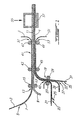
- FIGURE 1 With particular reference to FIGURE 1, given as non-limiting, it will be seen that the production of a laminated stack of large surface 1 is carried out by a continuous process as illustrated.
- the laminating device illustrated With a polypropylene film 3 of a thickness of approximately 20 ⁇ m previously treated by metallization / plating of nickel 5 in a manner known in the art (U.S. Patent No. 5,423,974) and a thickness less than about 5 ⁇ m, so as to coat the film with polypropylene 3 with a peelable layer of nickel 7 with a thickness of 2 ⁇ m.
- the rolling device is supplied with a film 9 of a thickness between about 10 and 30 ⁇ m mainly comprising lithium metallic and intended to constitute the anode 11 of the laminated mother cell of large area 1.
- a second rolling mill 19 is also fed. of the rolling device with another polypropylene film 21 which is coated in 23 in a known manner, with a polymer electrolyte film 25, of which the thickness can vary between around 5 and 30 ⁇ m, before introducing it into the rolling mill 19 between cylinders 27 and 29.
- a polymer electrolyte film 25 of which the thickness can vary between around 5 and 30 ⁇ m, before introducing it into the rolling mill 19 between cylinders 27 and 29.
- a third polypropylene film 31 is simultaneously fed at the rolling mill 19, but beforehand it is coated with a layer of nickel 33 with a thickness of less than about 5 ⁇ m, by a step of metallization / plating well known to those skilled in the art, in 35. Before its introduction into the rolling mill 19 and after having been coated with nickel thickness of 2 ⁇ m, the nickel coated polypropylene film is coated in 37 a cathode film 39. The polypropylene film 31, coated with nickel 33 and coated with cathode 39 is then introduced into the rolling mill 19 at the same time while the polypropylene film 21 coated with electrolyte 25.
- Ni ° / Li ° laminate at 13 and that made of polypropylene laminate - electrolyte - cathode are introduced into the rolling mill 41 consisting of cylinders 43, 45 and 47, 49, but beforehand we had peeled the film polypropylene 21 in 42.
- the support film is peeled 3 in 51, and the support film 31 in 53 and a laminated mother stack of large surface whose anode consists mainly of lithium metallic, the separator of a gelled or not gelled polymer electrolyte and the cathode of a composite material bound by a gelled polymer electrolyte or no; the anode is covered with a thin conductive coating inert to lithium such as, for example, metallic nickel; the composite cathode also has an inert conductive coating.
- the coatings external conductors are chosen thin, preferably less than 5 ⁇ m, so as to make them negligible compared to the thickness of the sum of the other components of the laminate and so as to keep the assembly flexible and easy to manipulate.
- These conductive coatings are preferably inert to the electrodes with which they are in contact for ensure the quality of electrical contacts.
- inert conductive coating we mean materials that are chemically and electrochemically stable with the active material of the corresponding electrode. In a way optional, these coatings can be more or less adherent so to facilitate the positioning of individual or multiple stacks cut when assembled into a complete generator.
- the different components of the laminated stack are welded together but the assembly retains a some flexibility due to the plastic nature of lithium, electrolyte polymer and thin conductive coatings. Note that the peeling operations indicated in FIGURE 1 are effective before the cutting and placing in the laminated stack.
- the live cutting of the mother roll 1 is carried out by means mechanical, schematically illustrated in 55, so as to obtain batteries of smaller area 57.
- FIGURES 2 (a), 2 (b) and 2 (c) illustrate the effect of cutting on the edges of the stack which become inaccessible for taking side contacts. Only the external faces are then accessible for the making contact.
- a thin inert conductive coating is used which ensures the quality of the electrical contact and physically isolates the material other batteries or packaging material. So no restrictive, two types of coatings are illustrated in FIGURES 2 (a), 2 (b) and 2 (c).
- a thin metallic coating in this case a 2 ⁇ m nickel thick, and two examples of composite coatings; one consisting of carbon and an inert and non-conductive binder stable in oxidation such as EPDM, PVDF or PVDF-HFP and used at the cathode; the other constituted a metallic conductive boron nitride powder and a stable binder reduction such as EPDM and used at the anode.
- Various compounds inert to lithium and conductors can satisfy these two criteria, in particular, for example, carbides, nitrides and metal borides.
- compounds inert to lithium means materials that are chemically and electrochemically stable against lithium.
- the lateral conductivity of the positive composite and its conductive composite coating so as to limit the short-circuit current temporary cutting, especially in the main laminate surface in order to preserve the state of charge and for safety reasons when the batteries thus cut are optimized for high powers of discharge.
- FIGURES 3 (a), 3 (b) and 3 (c) illustrate respectively assembly when required of the individual stacks in parallel 59, in a zigzag obtained by folding after cutting, or in series, by stacking the stacks, individual 61 or connected in parallel 63 in order to increase the voltage.
- the conductive coatings of the electrodes ensure electrical contacts between units, as shown, for example, in FIGURES 3 (a), 3 (b) and 3 (c).
- Single casing of batteries or sets of batteries series / parallel is made possible by the fact that all the components are in the solid state or without excess solvent, for gelled systems, which avoids the effects of local corrosion, especially for series mounting.
- Sealing of the electrochemical assembly and packaging materials is done using metallic barrier materials as needed collector of the entire electrochemical device. In a way optional, we will take advantage of the adhesion of the conductive coatings of the electrodes to ensure the positioning of the battery or batteries in the housing.
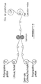
- FIGURES 4 to 9 we will see more particularly in FIGURE 4, how to make a conductive nickel coating adhered to a thin strip of lithium, the whole being obtained by lamination of a strip of lithium supported on plastic as described in U.S. Patent Nos. 5,423,974 and 5,521,028 with a thin nickel strip of 2 ⁇ m supported on a peelable plastic support.
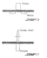
- FIGURE 6 How to cut small area stacks from the stack laminated using a cookie cutter is illustrated in FIGURE 6.
- FIGURE 7 How to Cut Stacks into Strips from the Stack laminated using a rotary knife is illustrated in FIGURE 7.
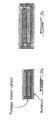
- FIGURE 8 Examples of battery sizes cut on the one hand wins beep or on the other hand with a rotary knife from the mother roll are illustrated in FIGURE 8.
- FIGURES 8 and 9 How to stack single or zigzag stacks in series when we want to develop an effective surface greater than that of the pile wrapped and a multiple voltage of a unit cell is shown in FIGURES 8 and 9.
- FIGURE 9 Examples of packaged unit voltage and voltage batteries multiple are illustrated in FIGURE 9.
- the active material of the cathode can be chosen from cobalt oxide, nickel oxide, nickel cobalt oxide, nickel oxide cobalt aluminum, manganese oxide (LiMn 2 O 4 ) or their analogues for so-called 4V cathodes or also among cathodes of less than 4V such as phosphates or other polyanions of transition metals such as LiFePO 4 , Nasicons structures also including V 2 O 5 , LiV 3 O 8 and MnO 2 , chalcogenides, oxocarbonates such as rhodizonate and halides such as monofluorinated carbons (CF) n .
- the nature of the active material at the cathode is not a limitation of the present invention.
- the electrolytic component can consist of either a ethylene oxide copolymer as described in U.S. Patents Nos. 4,578,326 and 4,758,483 in which at least one alkaline salt is dissolved and which may or may not contain polar aprotic solvent (s), or a gel formed polymers poorly solvating lithium salts or poorly conductive intrinsic in the presence of salts but comprising heteroatoms such as fluorine or polar groups such as nitriles, sulfonates, fluoromethanes, which make them miscible with one or more solvents polar aprotic organic. The latter then give the gel solvating properties of lithium salts so as to give them a role of electrolytic component.
- a ethylene oxide copolymer as described in U.S. Patents Nos. 4,578,326 and 4,758,483 in which at least one alkaline salt is dissolved and which may or may not contain polar aprotic solvent (s), or a gel formed polymers poorly solvating
- the main poorly solvating polymers can be, by way of nonlimiting example, the PVDFs or their copolymers, the polyacrylonitriles and polyelectrolytes comprising groups sulfonates or fluorosulfonates or their equivalents.
- the nature of the electrolytic component is not a limitation of the present invention.
- the cathode may also contain an inert binder facing the material electrode and polar aprotic solvent such as for example not limitative, EPDM.
- polar aprotic solvent such as for example not limitative, EPDM.
- the nature of the cathode binder is not a limitation of the present invention.
- the active material of the anode can be chosen from lithium metal, metallic sodium or an alloy thereof.
- alloy is meant a mixture containing a majority fraction of these alkali metals with one or more other components so that, when cutting, the chemical or electrochemical reaction of the alkali metal with the cathode either sufficient to allow self-healing.
- the exact composition of the lithium or sodium anode is not a limitation of this invention.
- the alkaline salt (s) may be lithium, sodium, potassium or other salts such as, for example, the salts based on lithium trifluoromethanesulfonimide described in US Pat. No. 4,505,997, the lithium salts derived from bisperhaloacyl or sulfonylimide crosslinkable or not described in US Patent No. 4,818,644 and in PCT WO92 / 02966, LiPF 6 , LiBF 4 , LiSO 3 CF 3 , LiClO 4 , LiSCN, NaSCN, NaClO 4 , KSCN and KClO 4 , etc.
- the nature of the salt is not a limitation of the present invention.
- the polar aprotic solvent (s) can be chosen, for example, from propylene carbonate, ethylene carbonate, ethyl methyl carbonate, dimethyl carbonate, diethyl carbonate, tetrahydrofuran, 2 -methyltetrahy drofuran, 1,3-dioxolane, 2,2-dimethyl-1,3-dioxolane, ⁇ -butyrolactone, butylene carbonate, sulfolane, 3-methylsulfolane, ter-bytyl-ether, 1,2-dimethoxyethane, 1,2-diethoxyethane, bis (methoxyethyl) ether, 1,2-ethoxymethoxyethane, terbutylmethylether, glymes and sulfonamides of formula: R 1 R 2 N-SO 2 -NR 3 R 4 , in which R 1 , R 2 , R 3 and R 4 are alkyls comprising
- the laminate includes the following: Ni ° (2 ⁇ m) / Li ° (24 ⁇ m) / Polymer electrolyte (30 ⁇ m) / Composite cathode (45 ⁇ m) / A1 (13 ⁇ m).
- the starting laminate is obtained by continuously coating the cathode on its collector and the electrolyte on a peelable support followed by a hot transfer of the electrolyte on the cathode and peeling of the temporary support; the lithium anode is then transferred with its nickel collector as obtained in FIGURE 4.
- the composite cathode comprises vanadium oxide, carbon black and the polymer electrolyte as a binder.
- the polymer electrolyte which also serves as a separator consists of a copolymer of ethylene oxide in which a lithium salt, (CF 3 SO 2 ) 2 NLi, is dissolved in an O / Li ratio of 30 / 1.
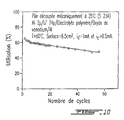
- the behavior in cycling is identical in all points to the behavior in cycling of the starting laminate not cut to the raw when represented proportionally by unit of surface. Only a self-healing phenomenon resulting from an electrochemical dissolution of lithium when brought into contact with the positive electrode explains this result.
- Number of the battery cut under an inert atmosphere Battery voltage after cutting (volts) Battery voltage 1 hour after cutting (volts) 1 3.156 3,410 2 3.202 3.341 3 3.405 3,433 4 0.001 3,016 5 3, 407 3,445 6 3.109 3.331 7 3.387 3.405 8 3,201 3,295 9 0.003 3.105 10 2.797 3.204 11 3.388 3,424 12 3.316 3,410 laminated mother 2,697 3.322
- Example 1 is reproduced, this time replacing the cathode with a second lithium film.
- the laminate thus produced comprises the following elements: Ni ° (2 ⁇ m) / Li ° (24 ⁇ m) / Polymer electrolyte (20 ⁇ m) / Li ° (24 ⁇ m) / Ni ° (2 ⁇ m)
- an impedance measurement shows an interface resistance of 30 ⁇ / cm 2 for the laminated mother stack.
- five stacks of circular shape are taken in a glove box under an argon atmosphere using a cookie cutter.
- a measurement of the impedance of each of these batteries as soon as cutting shows that the battery is short-circuited.
- a second impedance measurement is carried out, the five batteries are still in short circuit demonstrating that the battery cannot self-heal without a reaction of lithium with the active component of the cathode.
- the absence of a lithium reagent does not allow healing at the edge.
- a pile is then treated with a solution of ethyl alcohol to heal the bone. After this treatment, an impedance measurement is made showing that the short circuit is eliminated, the stack then has an impedance similar to that obtained for the laminated mother stack.
- the laminate includes the following: Ni ° (2 ⁇ m) / Li ° (24 ⁇ m) / Polymer electrolyte (15 ⁇ m) / Composite cathode (40 ⁇ m) / A1 (13 ⁇ m).
- the composite cathode includes vanadium oxide, carbon black and polymer electrolyte as a binder.
- the polymer electrolyte which also serves as a separator consists of a copolymer of ethylene oxide in which a lithium salt, (CF 3 SO 2 ) 2 NLi, is dissolved in an O / Li ratio of 30 / 1.
- the US copolymers patents Nos 4,578,326 and 4,758,483 describe non-limiting examples of copolymers which can be used for the process of the invention. These copolymers can be crosslinked if necessary by means known to those skilled in the art.
- Example 3 is reproduced in an anhydrous chamber using this time a gelled polymer electrolyte obtained by beam irradiation electron, EB, at a dose of 5 Mrad.
- the electrolyte is composed by volume of 50% glycerol-tri [poly (oxyethylene) (oxypropylene)] triacrylate and 50% of a mixture of salty polar aprotic solvent consisting of ethyl methyl carbonate and ethylene carbonate (in a 1: 1 volume ratio) and lithium hexafluorophosphate at one concentration of 1 molar (available from Tomiyama).
- the electrolyte gelled polymer obtained has good ionic conductivity at 25 ° C and sufficient mechanical properties to serve as a separator in the pile.
- the laminate includes the following: Ni ° (2 ⁇ m) / Li ° (24 ⁇ m) / Polymer electrolyte (30 ⁇ m) / Composite cathode (45 ⁇ m) / A1 (13 ⁇ m).
- Ethyl alcohol is used in this example, but others reactive liquids or gases can also be used depending on the nature of the compound of oxidized lithium which one wishes to obtain to ensure the good generator operation.
- This example concerns a cutting of two batteries identical to those described in Example 5 except that the cutter edge is lubricated by a toluene solution containing by volume 40% of a mixture of monomers consisting of 40% pentaerythritol tetraacrylate and 60% methyl methacrylate (available from Polysciences).
- a toluene solution containing by volume 40% of a mixture of monomers consisting of 40% pentaerythritol tetraacrylate and 60% methyl methacrylate (available from Polysciences).
- a polymerization reaction which forms a thin, hard and insulating film electric coming to mechanically consolidate the edge of the pile.
- Both batteries present after cutting a voltage of 3.33 volts.
- the consolidation of the edge has been demonstrated from a mechanical penetration test.
- the measuring device consists of a point 7mm in diameter under a thrust of 240 g.
- a first penetration measurement was taken in the center of the stack and a second measurement on the edge.
- TABLE III shows the percent penetration variations observed during this test. Penetration in the center of the stack Penetration at the edge of the pile Battery 1 10% 8% Battery 2 10% 7%
Description
La présente invention concerne des piles au lithium ultra-minces et à l'état solide et leur procédé de fabrication. De façon plus générale, l'invention se rapporte à un procédé de fabrication de piles minces à électrolyte polymère et à anode de lithium ou de sodium, ainsi qu'aux piles obtenues par ce procédé. Plus particulièrement, l'invention se rapporte à la préparation de piles à électrolyte polymère à partir d'une pile laminée-mère qu'on découpe à vif mécaniquement. En d'autres termes, la présente invention concerne l'utilisation d'une pile laminée de grande surface préparée par des procédés en continu dont le design est particulièrement favorable à la fabrication de plus petits éléments par simple découpe directe du laminé ainsi que le procédé de fabrication de petites piles ultra-minces par découpe mécanique.The present invention relates to ultra-thin lithium batteries and to the solid state and their manufacturing process. In a general view, the invention relates to a method for manufacturing thin batteries with polymer electrolyte with lithium or sodium anode, as well as batteries obtained by this process. More particularly, the invention relates to the preparation of polymer electrolyte batteries from a mother-roll battery that are cut open mechanically. In other words, this invention relates to the use of a large surface laminated stack prepared by continuous processes whose design is particularly favorable to the production of smaller elements by simple direct cutting laminate as well as the manufacturing process of small ultra-thin batteries by mechanical cutting.
Au cours des dix dernières années les piles au lithium de type primaire et rechargeable ont fait l'objet d'un nombre considérable de travaux de recherche et de développement. L'objectif est de développer une pile peu coûteuse, ayant un grand contenu énergétique et de bonne performances électrochimiques. Dans cette optique de nombreuses configurations de pile ont été développées pour répondre aux différentes applications telles la micro-électronique, les télécommunications, les ordinateurs portables et le véhicule électrique pour ne nommer que ceux là.Over the past ten years primary type lithium batteries and rechargeable have been the subject of a considerable number of works by research and development. The goal is to develop a little stack expensive, having a high energy content and good performance electrochemical. With this in mind, many battery configurations have been developed to meet different applications such as microelectronics, telecommunications, laptops and electric vehicle to name a few.
Les piles ou générateurs électrochimiques, qu'ils soient rechargeables ou non, sont tous constitués d'une anode qui elle peut être constituée d'un métal comme le lithium, d'une cathode qui elle est constituée d'un composé d'insertion, insérant de manière réversible ou non les ions alcalins, comme l'oxyde de vanadium ou le dioxyde de manganèse, d'un séparateur mécanique placé entre les électrodes, et d'une composante électrolytique. Par composante électrolytique on entend toute matière comprise dans le générateur servant au transport ionique, à l'exception des matériaux actifs de l'électrode, dans lesquels les ions Li+ peuvent se déplacer, tant au niveau du séparateur que dans l'électrode composite. Lors de la décharge ou de la charge du générateur, la composante électrolytique assure le transport des espèces ioniques à travers tout le générateur soit d'une électrode à l'autre et à l'intérieur même de l'électrode composite. Dans une pile à électrolyte polymère, les fonctions de séparateur et de composante électrolytique sont généralement réunies dans un seul et même matériau.The electrochemical cells or generators, whether rechargeable or not, all consist of an anode which may consist of a metal such as lithium, of a cathode which it consists of an insertion compound, inserting, in a reversible manner or not, the alkaline ions, such as vanadium oxide or manganese dioxide, a mechanical separator placed between the electrodes, and an electrolytic component. By electrolytic component is meant any material included in the generator used for ion transport, with the exception of the active materials of the electrode, in which the Li + ions can move, both at the level of the separator and in the composite electrode. When discharging or charging the generator, the electrolytic component ensures the transport of ionic species throughout the generator either from one electrode to another and inside the composite electrode itself. In a polymer electrolyte battery, the functions of separator and electrolytic component are generally combined in one and the same material.
Les petites piles au lithium, rechargeables ou non, telles que les piles boutons et les piles plates sont généralement fabriquées par l'élaboration et la découpe des composantes individuelles qui sont par la suite assemblées. Dans certains cas de piles plates constituées de films minces, les piles ou leurs composantes sont élaborées sous forme de piles ou d'éléments multiples de dimension prédéterminée qui sont par la suite découpées dans des zones inactives électrochimiquement prévues à cet effet de façon à permettre la découpe locale sans dommages pour le dispositif électrochimique. Des exemples de piles utilisant ce procédé de fabrication sont décris dans les brevets U.S. Nos 4.177.330, 5.378.557 et 5.547.780.Small lithium batteries, rechargeable or not, such as batteries buttons and flat batteries are usually made by developing and the cutting of the individual components which are then assembled. In some cases of flat batteries made of thin films, the batteries or their components are developed in the form of stacks or elements multiples of predetermined dimension which are then cut out from electrochemically inactive zones provided for this purpose so as to allow local cutting without damage to the device electrochemical. Examples of batteries using this manufacturing process are described in U.S. Patent Nos. 4,177,330, 5,378,557 and 5,547,780.
Dans la plupart de ces cas, les électrodes actives: lithium métallique et cathode composite, sont directement en contact avec le matériau d'emballage qui sert alors de barrière de protection et de collecteur de courant; souvent ces électrodes sont élaborées directement sur le matériau d'emballage par enduction ou par pressage. Cette combinaison de deux fonctions: barrière et collecteur sur un même matériau, permet alors d'optimiser le poids et le volume de la pile complète.In most of these cases, the active electrodes: metallic lithium and composite cathode, are in direct contact with the material packaging which then serves as a protective barrier and collector of current; often these electrodes are produced directly on the material packaging by coating or pressing. This combination of two functions: barrier and collector on the same material, then allows optimize the weight and volume of the complete stack.
Cette façon de faire possède cependant plusieurs inconvénients:
- le besoin de prédéterminer les dimensions et la position des éléments ou des piles lors de la fabrication d'éléments multiples à découper;
- les pertes en matériel et en optimisation associées aux débordements et au prépositionnement requis par les opérations de découpe et de scellement de l'ensemble du dispositif;
- les problèmes de positionnement des éléments les uns sur les autres lors de l'assemblage ou de la découpe;
- la surépaisseur requise pour qu'un même matériau puisse servir à la fois comme barrière étanche à l'air et à l'eau et comme collecteur. Cette surépaisseur devient particulièrement pénalisante dans les assemblages de piles constituées de films minces misent en série ou en parallèle, i.e., lorsque plusieurs piles individuelles sont superposées pour développer le voltage ou l'ampérage voulu.
- the need to predetermine the dimensions and position of the elements or stacks when manufacturing multiple elements to be cut;
- losses in material and optimization associated with overflows and prepositioning required by the cutting and sealing operations of the entire device;
- problems of positioning the elements on top of each other during assembly or cutting;
- the extra thickness required for the same material to serve both as an air and water tight barrier and as a collector. This extra thickness becomes particularly disadvantageous in the assemblies of cells made up of thin films bet in series or in parallel, ie, when several individual cells are superimposed to develop the desired voltage or amperage.
La découpe mécanique d'une pile à électrolyte polymère en morceaux est a priori possible, toutefois il est généralement perçu que la découpe induit des courts-circuits et laisse des points faibles surtout lorsque cette opération est faite avec des moyens mécaniques (brevet U.S. No 5.250.784); ce que confirme indirectement les procédés plus complexes de découpe de piles multiples (brevets U.S. Nos 5.378.557 et 5.547.780) où l'on découpe dans des zones pré-déterminées non-électrochimiquement actives. Plusieurs fois les inventeurs ont réalisé la découpe mécanique d'une pile laminée en films minces à l'aide, par exemple, d'une paire de ciseaux sans perte permanente du voltage des pièces. Toutefois ces essais effectués sous air ambiant ne pouvait suggérer un procédé de fabrication car, d'une part, ils reposent sur l'oxydation irréversible du lithium par l'eau et les composants de l'air et d'autre part parce qu'il est connu que la découpe mécanique elle même crée des zones favorables au développement des courts-circuits, notamment lors du cyclage, par suite du travail mécanique de découpe qui tend à rapprocher les collecteurs de l'anode et de la cathode.Mechanical cutting of a polymer electrolyte battery in pieces is a priori possible, however it is generally perceived that the cutting induces short circuits and leaves weak points especially when this is done with mechanical means (U.S. Patent No 5,250,784); which indirectly confirms the more complex processes of cutting multiple batteries (U.S. Patent Nos. 5,378,557 and 5,547,780) where we cut in pre-determined areas non-electrochemically active. Several times the inventors have carried out the mechanical cutting of a stack laminated into thin films using, for example, a pair of scissors without permanent loss of parts voltage. However these tests performed under ambient air could not suggest a manufacturing process because, on the one hand, they are based on the irreversible oxidation of lithium by water and air components and secondly because it is known that cutting mechanical itself creates zones favorable to the development of short circuits, especially during cycling, due to mechanical work cutting which tends to bring the collectors closer to the anode and the cathode.
L'invention a pour objet la fabrication de piles à électrolyte polymère et à anode de lithium ou de sodium qui fait intervenir un effet surprenant d'auto-cicatrisation de l'anode, ce qui facilite la découpe en petits éléments avec un taux de rejet faible ou nul.The subject of the invention is the manufacture of batteries with polymer electrolyte and with lithium or sodium anode which involves a surprising effect self-healing of the anode, which facilitates cutting into small elements with little or no rejection rate.
L'invention a aussi pour objet un procédé de découpe d'une pile laminée-mère qui ne laisse pas de points faibles électrochimiquement tel que démontré par le cyclage électrochimique de piles réalisées selon l'invention.The invention also relates to a method for cutting a stack. mother laminate which does not leave weak points electrochemically such as demonstrated by the electrochemical cycling of batteries produced according to the invention.
L'invention a pour autre objet un procédé de fabrication de piles qui, de façon non-limitatif, fait intervenir la dissolution chimique ou électrochimique du lithium ou sodium métallique lorsque mis en contact avec le matériau de la cathode afin de rationaliser le mécanisme d'auto-cicatrisation. Another subject of the invention is a method for manufacturing batteries which, non-limitingly, involves chemical dissolution or electrochemical lithium or metallic sodium when contacted with the cathode material in order to rationalize the self-healing mechanism.
L'invention a aussi pour objet de démontrer par des exemples qu'un mécanisme d'auto-cicatrisation existe qui tend à résorber le court-circuit souvent provoqué par la découpe mécanique et ce, même en l'absence d'air et d'eau.The invention also aims to demonstrate by examples that self-healing mechanism exists which tends to absorb the short circuit often caused by mechanical cutting, even in the absence of air and water.
L'invention a encore pour objet de démontrer par des essais de cyclage que le phénomène d'auto-cicatrisation tend à éliminer le lithium des zones de découpe.The object of the invention is also to demonstrate by tests of cycling that the phenomenon of self-healing tends to eliminate lithium from cutting areas.
Un autre objet de l'invention réside en la conception d'un procédé de fabrication simplifié basé sur la découpe à vif d'une pile de grande surface préparée par des procédés continus, sans avoir à présumer à l'avance de la forme ou de la dimension de la pile à produire.Another object of the invention lies in the design of a method of simplified manufacturing based on the sharp cutting of a large surface stack prepared by continuous processes, without having to presume in advance of the shape or size of the pile to be produced.
L'invention concerne un procédé de fabrication de piles à électrolyte polymère gélifié ou non et à anode à base de lithium ou de sodium, à partir d'une pile-mère laminée de grande surface comportant un feuillard d'anode à base de lithium ou de sodium, un électrolyte polymère ainsi qu'une cathode sous forme de film mince, caractérisé en ce que la cathode a la propriété de dissoudre le lithium ou le sodium, et l'on effectue une découpe mécanique à vif de la pile-mère faisant en sorte de mettre en jeu un phénomène d'auto-cicatrisation résultant en une dissolution chimique dans la cathode de tout lithium ou sodium ayant été en contact avec la cathode au cours de la découpe.The invention relates to a method for manufacturing electrolyte batteries. polymer gelled or not and with anode based on lithium or sodium, from of a large surface laminated mother cell comprising an anode strip with lithium or sodium base, a polymer electrolyte and a cathode in the form of a thin film, characterized in that the cathode has the property of dissolve the lithium or the sodium, and a mechanical cutting is carried out vivid of the mother battery making it possible to bring into play a phenomenon of self-healing resulting in chemical dissolution in the cathode of everything lithium or sodium having been in contact with the cathode during the cutting.
De préférence, l'anode est à base de lithium métallique. D'autre part, il est préférable que l'électrolyte polymère soit conducteur des ions alcalins de l'anode et qu'il agisse également comme séparateur entre l'anode et la cathode.Preferably, the anode is based on metallic lithium. On the other hand, it is preferable that the polymer electrolyte conducts alkaline ions of the anode and that it also acts as a separator between the anode and the cathode.
Selon une autre réalisation préférée, la pile-mère comporte une cathode composite constituée d'un composé réductible au lithium ou au sodium, d'un additif de conduction électronique et d'un liant électrolyte polymère. De plus, on peut prévoir un revêtement conducteur électronique mince sur la face externe de l'anode et éventuellement de la cathode, dont le matériau conducteur est chimiquement et électrochimiquement inerte vis-à-vis du matériau d'électrode et sert également à établir des contacts électriques permanents sur les faces externes des piles découpées. L'épaisseur du revêtement conducteur de l'anode et éventuellement de la cathode est de préférence inférieur à 5 micromètres (µm) de façon à minimiser le poids et le volume et à conserver la flexibilité de l'ensemble de la pile mince.According to another preferred embodiment, the mother battery comprises a composite cathode made of a compound reducible to lithium or sodium, an electronic conduction additive and an electrolyte binder polymer. In addition, an electronic conductive coating can be provided. thin on the external face of the anode and possibly of the cathode, the conductive material is chemically and electrochemically inert towards electrode material and is also used to make contacts permanent electrics on the external faces of the cut batteries. The thickness of the conductive coating of the anode and possibly of the cathode is preferably less than 5 micrometers (µm) so as to minimize weight and volume and retain the flexibility of the entire the thin stack.
Le revêtement conducteur est par exemple un mince feuillard métallique à base de nickel ou de fer tel que décrit dans le brevet U.S. No 5.423.974. Il peut aussi être constitué d'une composite comportant un liant polymère inerte et une charge conductrice électronique dispersée et inerte vis-à-vis du matériau d'électrode. Quant à la charge conductrice, cette dernière peut être une poudre conductrice inerte au lithium comprenant, de façon non-limitative, des nitrures, carbures et borures métalliques, dans le cas de l'anode ou elle peut comprendre également du carbone dans le cas du revêtement conducteur de la cathode. Le liant polymère inerte est non conducteur ionique et peut comprendre, à titre non-limitatif, des motifs monomères éthylène et propylène, par exemple le liant polymère est choisi parmi le polyéthylène, le polypropylène ou le copolymère éthylène propylène diene (EPDM). Le liant polymère inerte peut être préparé à partir de prépolymères et/ou de monomères fonctionnels réticulables facile à mettre en oeuvre. A titre d'exemple non-limitatif de groupements fonctionnels on retrouve : les acrylates, les méthacrylates, les allyles, les vinyles ou une combinaison de ces derniers. Dans le cas de la cathode, le liant polymère inerte peut comprendre également des motifs fluorés, dont le fluorure de vinyldiene (PVDF) ou le copolymère de fluorure de vinyldiene - co-hexafluoropropène (PVDF-HFP). Le choix du liant inerte est basé en premier lieu sur sa compatibilité avec les matériaux actifs de l'électrode correspondante.The conductive coating is for example a thin strip metallic based on nickel or iron as described in U.S. Patent No. 5,423,974. It can also consist of a composite comprising a binder inert polymer and a dispersed and inert electronic conductive filler vis-à-vis the electrode material. As for the conductive load, this the latter may be an inert conductive lithium powder comprising, non-limiting way, nitrides, carbides and metal borides, in the case of the anode or it may also include carbon in the case of the conductive coating of the cathode. The inert polymeric binder is not ionic conductor and may include, without limitation, patterns ethylene and propylene monomers, for example the polymeric binder is chosen from polyethylene, polypropylene or ethylene copolymer propylene diene (EPDM). The inert polymeric binder can be prepared from easy to crosslinkable prepolymers and / or functional monomers enforce. As a non-limiting example of groupings functional we find: acrylates, methacrylates, allyles, vinyls or a combination thereof. In the case of the cathode, the inert polymeric binder may also comprise fluorinated units, the vinyldiene fluoride (PVDF) or the copolymer of vinyldiene fluoride - co-hexafluoropropene (PVDF-HFP). The choice of inert binder is based on first place on its compatibility with the active materials of the electrode corresponding.
Dans certains cas, le liant polymère inerte pourra être un adhésif, notamment un thermo-adhésif, de façon à faciliter le positionnement des piles et la qualité des contacts électriques.In some cases, the inert polymeric binder may be an adhesive, in particular a thermo-adhesive, so as to facilitate the positioning of the batteries and the quality of the electrical contacts.
Le revêtement conducteur composite devrait posséder une résistance de surface variant entre 0.1 et 1000 Ω/cm2, préférentiellement entre 1 et 300 Ω/cm2, de façon à limiter un courant de court-circuit lors de la découpe, pour des raisons de maintien de l'état de charge et pour la sécurité des opérations de découpe.The composite conductive coating should have a surface resistance varying between 0.1 and 1000 Ω / cm 2 , preferably between 1 and 300 Ω / cm 2 , so as to limit a short-circuit current during cutting, for reasons of maintenance. of the state of charge and for the safety of cutting operations.
Selon une autre réalisation, la pile-mère est obtenue à partir de films continus d'anode, de cathode et d'électrolyte polymère, lesquels sont assemblés par des procédés d'enduction et de transfert de films, ces films étant adhérents entre eux. Au besoin, des étapes de réticulation sont utilisées avant ou après l'enduction ou le transfert des films.According to another embodiment, the mother battery is obtained from films of anode, cathode and polymer electrolyte, which are assembled by coating and film transfer processes, these films being adherent to each other. If necessary, crosslinking steps are used before or after coating or transfer of films.
Une fois les piles minces obtenues, on peut les empiler en parallèle ou en série, ou on peut les empiler après pliage en zigzag. On peut aussi mettre dans un emballage constitué par un boítier unique, les piles minces individuelles ou empilées en parallèles ou en série.Once the thin batteries are obtained, they can be stacked in parallel or in series, or they can be stacked after zigzag folding. Can also put in a package consisting of a single box, thin batteries individually or stacked in parallel or in series.
Selon une autre réalisation de l'invention, la pile-mère laminée comporte un film de support pelable sur au moins une de ses faces de façon à faciliter sa production et sa manipulation. Ce film support pelable est constitué préférentiellement et de façon non-limitative de polypropylène ou de polyéthylène, et on l'enlève juste avant l'opération de découpe des piles.According to another embodiment of the invention, the laminated mother battery has a peelable support film on at least one of its faces so to facilitate its production and handling. This peelable backing film is preferably and without limitation made of polypropylene or polyethylene, and it is removed just before the battery cutting operation.
L'électrolyte polymère du séparateur et au besoin de l'électrode est notamment constitué de masse moléculaire supérieure à 50 000 de façon à obtenir des films manipulables et transférables par des procédés de laminage en continu. On peut aussi utiliser un électrolyte polymère gélifié de façon à optimiser la conductivité ionique à la température ambiante. Par polymère gélifié on entend une matrice polymère capable d'incorporer un solvant organique aprotique polaire de façon à former un gel.The polymer electrolyte in the separator and, if necessary, the electrode is in particular made up of molecular mass greater than 50,000 so as to obtain films which can be handled and transferred by continuous rolling. You can also use a gelled polymer electrolyte so as to optimize the ionic conductivity at room temperature. Through gelled polymer means a polymer matrix capable of incorporating a polar aprotic organic solvent to form a gel.
Selon une autre réalisation, l'électrolyte polymère est constitué d'une matrice polymérique et on rend cette dernière conductrice par l'ajout d'au moins un solvant aprotique polaire et d'un sel de métal alcalin soluble dans l'électrolyte. Cette addition d'un solvant liquide aprotique polaire peut se faire après l'opération de découpe de façon à minimiser le courant de court-circuit lors de la découpe. Il en est de même pour le sel alcalin qu'on ajoute de préférence après l'opération de découpe de façon à minimiser le courant de court-circuit. Lors de l'opération de découpe, il est également possible de refroidir la pile à une température inférieure à celle de la transition vitreuse de l'électrolyte de manière à réduire la conductivité ionique.According to another embodiment, the polymer electrolyte consists of a polymer matrix and the latter is made conductive by the addition of minus a polar aprotic solvent and an alkali metal salt soluble in the electrolyte. This addition of a polar aprotic liquid solvent can be do after the cutting operation so as to minimize the short-circuit current when cutting. It is the same for the alkaline salt that we add preferably after the cutting operation so as to minimize the current short circuit. During the cutting operation, it is also possible to cool the cell to a temperature lower than that of the glass transition of the electrolyte so as to reduce the ionic conductivity.
L'ajout de solvants aprotiques polaires ou de sel ou des deux après l'assemblage de la pile peut être facilité par l'usage d'au moins un revêtement conducteur composite perméable afin de faciliter l'introduction de ces derniers.Adding polar aprotic solvents or salt or both after battery assembly can be facilitated by the use of at least one permeable composite conductive coating to facilitate introduction of these.
L'opération de découpe peut s'effectuer mécaniquement de façon connu dans l'art au moyen d'outils de poinçonnage (blanking), d'écrasement (crush cutting) ou de cisaillement (score cutting) ou encore la découpe s'effectue avec un outil constitué au moins en partie d'un matériau isolant de façon à minimiser le court-circuit lors de la découpe. La découpe peut aussi s'effectuer en présence d'un lubrifiant inerte ou réactif au lithium. Durant ou après l'opération de découpe, on peut effectuer une réaction chimique du lithium ou du sodium de l'arête découpée de façon à éliminer plus rapidement tout court-circuit et à neutraliser l'activité électrochimique latérale. Cette opération facilite le phénomène d'auto-cicatrisation mentionné dans cette invention. La réaction chimique s'effectue normalement en présence de réactifs capables d'oxyder le lithium de l'arête, et qui sont des liquides ou des gaz, notamment l'air, capables de former un composé du lithium isolant électrique, insoluble dans l'électrolyte polymère et pouvant également consolider l'arête. Le composé formé est par exemple à base de carbonates, d'oxyanions, d'oxydes, de chalcogénures, de dérivés du fluor ou d'alcoolates.The cutting operation can be done mechanically so known in the art by means of punching tools (blanking), crushing (score cutting) or shear (score cutting) or even cutting is carried out with a tool consisting at least in part of an insulating material of so as to minimize the short circuit during cutting. Cutting can also be carried out in the presence of an inert or reactive lithium lubricant. During or after the cutting operation, a chemical reaction can be carried out lithium or sodium from the cut edge to remove more quickly short circuit and neutralize electrochemical activity lateral. This operation facilitates the phenomenon of self-healing mentioned in this invention. The chemical reaction takes place normally in the presence of reagents capable of oxidizing the lithium of the edge, and which are liquids or gases, especially air, capable of forming a composed of electrically insulating lithium, insoluble in the polymer electrolyte and can also consolidate the edge. The compound formed is for example based on carbonates, oxyanions, oxides, chalcogenides, derivatives fluorine or alcoholates.
De façon optionnel, il est possible de consolider les arêtes de la pile, pour prévenir toute déformation indésirable, par une réaction de polymérisation à l'arête lors de la découpe. La réaction étant catalysée ou amorcée par le métal alcalin fraíchement découpé.Optionally, it is possible to consolidate the edges of the stack, to prevent any undesirable deformation, by a reaction of edge polymerization during cutting. The reaction being catalyzed or initiated by freshly cut alkali metal.
Selon une autre réalisation de l'invention, on replie sur elle-même, en zigzag, une partie de la pile découpée en un nombre impair d'unités de base et l'on termine l'ensemble par des faces ayant des polarités opposées. On peut aussi superposer les piles de façon à effectuer une infinité de montages parallèles et séries par simple empilement, ou on peut mettre les piles découpées individuellement ou par groupe dans un boítier unique en utilisant les faces externes des piles et des ensembles pour assurer la collection du courant.According to another embodiment of the invention, one folds back on itself, in zigzag, part of the stack cut into an odd number of base units and the assembly is ended by faces having opposite polarities. We can also stack the stacks so as to perform an infinite number of assemblies parallels and series by simple stacking, where you can put the stacks cut individually or in groups in a single box using the external faces of the batteries and assemblies to ensure the current collection.
L'invention concerne aussi une pile mince à électrolyte polymère constituée par la superposition d'une cathode sous forme de film mince, d'un électrolyte polymère ainsi que d'un feuillard d'anode à base de lithium ou de sodium, caractérisé en ce qu'elle est obtenue par découpe de ladite superposition de façon à ce que ses extrémités après découpe soient uniformément tranchées, qu'optionnelement on retrouve à l'arête un mince film obtenu par la réaction d'un lubrifiant réactif lors de la découpe qui vient consolider et isoler électriquement l'arête, et qu'enfin ladite pile conserve sensiblement le même voltage un fois produite que celui d'une pile-mère utilisée pour sa production par découpe.The invention also relates to a thin battery with polymer electrolyte constituted by the superposition of a cathode in the form of a thin film, of a polymer electrolyte as well as an anode strip based on lithium or sodium, characterized in that it is obtained by cutting said overlapping so that its ends after cutting are uniformly sliced, that optionally we find at the edge a thin film obtained by the reaction of a reactive lubricant during cutting which consolidates and electrically isolates the edge, and finally said pile retains substantially the same voltage when produced as that of a mother battery used for its production by cutting.
D'autres caractéristiques et avantages de l'invention ressortiront
d'ailleurs de réalisations préférées illustrées dans les dessins annexés,
donnés à titre purement illustratif mais sans caractère limitatif, et dans
lesquels,
En se référant plus particulièrement à la FIGURE 1, donnée à titre
non limitatif, on verra que la production d'une pile laminée de grande
surface 1 s'effectue par un procédé en continu tel qu'illustré. On alimente le
dispositif de laminage illustré avec un film de polypropylène 3 d'une
épaisseur d'environ 20µm préalablement traité par métallisation/placage de
nickel en 5 de façon connue dans l'art (brevet U.S. No 5.423.974) et d'une
épaisseur inférieure à environ 5µm, de façon à revêtir le film de
polypropylène 3 d'une couche pelable de nickel 7 d'une épaisseur de 2µm.
On alimente d'autre part le dispositif de laminage avec un film 9 d'une
épaisseur entre environ 10 et 30µm comprenant principalement du lithium
métallique et destiné à constituer l'anode 11 de la pile laminée-mère de
grande surface 1.With particular reference to FIGURE 1, given as
non-limiting, it will be seen that the production of a laminated stack of large
surface 1 is carried out by a continuous process as illustrated. We feed the
laminating device illustrated with a polypropylene film 3 of a
thickness of approximately 20µm previously treated by metallization / plating of
On introduit le film de polypropylène 3 revêtu d'une couche pelable
de nickel 7, ainsi que le film de lithium 9 dans le laminoir 13 constitué des
cylindres 15 et 17 tournant en sens inverse et entre lesquels s'effectuera le
laminage Ni°/Li°.Introducing the polypropylene film 3 coated with a peelable layer
nickel 7, as well as the
D'autre part, on alimente un second laminoir 19 faisant aussi partie
du dispositif de laminage avec un autre film de polypropylène 21 qu'on
enduit en 23 de façon connue, d'un film d'électrolyte polymère 25, dont
l'épaisseur peut varier entre environ 5 et 30µm, avant de l'introduire dans le
laminoir 19 entre les cylindres 27 et 29. On pourrait évidemment tout aussi
bien utiliser un électrolyte polymère gélifié sans pour cela sortir du cadre de
l'invention.On the other hand, a
Un troisième film de polypropylène 31 est simultanément alimenté
au laminoir 19, mais préalablement il est revêtu d'une couche de nickel 33
d'une épaisseur inférieure à environ 5µm, par une étape de
métallisation/placage bien connue de l'homme de l'art, en 35. Avant son
introduction dans le laminoir 19 et après avoir été revêtu de nickel d'une
épaisseur de 2µm, le film de polypropylène revêtu de nickel est enduit en 37
d'un film de cathode 39. Le film de polypropylène 31, revêtu de nickel 33
et enduit de la cathode 39 est alors introduit dans le laminoir 19 en même
temps que le film de polypropylène 21 enduit d'électrolyte 25. Le produit
de laminage Ni°/Li° en 13 et celui constitué du laminé polypropylène -
électrolyte - cathode sont introduits dans le laminoir 41 constitué des
cylindres 43, 45 et 47, 49, mais préalablement on avait pelé le film de
polypropylène 21 en 42. A la sortie du laminoir 41, on pèle le film support
3 en 51, et le film support 31 en 53 et l'on obtient une pile laminée-mère de
grande surface dont l'anode est constituée principalement de lithium
métallique, le séparateur d'un électrolyte polymère gélifié ou non et la
cathode d'un matériau composite lié par un électrolyte polymère gélifié ou
non; l'anode est recouverte d'un revêtement conducteur mince inerte au
lithium tel que, à titre d'exemple, le nickel métallique; la cathode composite
comporte également un revêtement conducteur inerte. Les revêtements
conducteurs externes sont choisis minces, préférentiellement inférieurs à 5
µm, de façon à les rendre négligeables vis-à-vis de l'épaisseur de la somme
des autres composantes du laminé et de façon à garder l'ensemble souple et
facile à manipuler. Ces revêtements conducteurs sont préférentiellement
inertes vis-à-vis des électrodes avec lesquelles ils sont en contact pour
assurer la qualité des contacts électriques. Par revêtement conducteur inerte
on entend des matériaux qui sont chimiquement et électrochimiquement
stable avec le matériau actif de l'électrode correspondante. De façon
optionnelle, ces revêtements peuvent être plus ou moins adhérents de façon
à faciliter le positionnement des piles individuelles ou multiples découpées
lors de leur assemblage en générateur complet. Les différentes composantes
de la pile laminée sont soudées ensemble mais l'ensemble conserve une
certaine flexibilité due à la nature plastique du lithium, de l'électrolyte
polymère et des minces revêtements conducteurs. On notera que les
opérations de pelages indiquées sur la FIGURE 1 sont effectives avant la
découpe et la mise en boítier de la pile laminée.A
La découpe à vif de la pile laminée-mère 1 s'effectue par des moyens
mécaniques, schématiquement illustrés en 55, de façon à obtenir des piles
de plus petite surface 57. On pourrait aussi produire de façon connue soit
des bandelettes transversales à la pile laminée, soit des petits éléments
entièrement découpés sur leur périphérie, soit des éléments perforés ou
évidés ou de formes variées en fonction des applications visées notamment
dans le domaine de la micro-électronique. Au besoin, on attendra un temps
minimum pour laisser les piles s'auto-cicatriser complètement et se stabiliser
en voltage de façon à pouvoir effectuer un contrôle de qualité de tous les
éléments.The live cutting of the mother roll 1 is carried out by means
mechanical, schematically illustrated in 55, so as to obtain batteries
of
Les FIGURES 2(a), 2(b) et 2(c) illustrent l'effet de la coupe sur les bords de la pile qui deviennent inaccessible pour des prises de contact latérales. Seules les faces externes sont alors accessibles pour la prise de contact. Pour faciliter ces contacts, notamment du côté de l'anode (oxydation du Li°), on utilise un mince revêtement conducteur inerte qui assure la qualité du contact électrique et isole physiquement le matériau d'électrode des autres piles ou du matériau d'emballage. De façon non limitative, deux types de revêtements sont illustrés aux FIGURES 2(a), 2(b) et 2(c). Un revêtement métallique mince, dans ce cas un nickel de 2 µm d'épaisseur, et deux exemples de revêtements composites; l'un constitué de carbone et d'un liant inerte et non-conducteur stable en oxydation tel que l'EPDM, le PVDF ou le PVDF-HFP et utilisé à la cathode; l'autre constitué d'une poudre de nitrure de bore conducteur métallique et d'un liant stable en réduction tel que l'EPDM et utilisé à l'anode. Divers composés inertes au lithium et conducteurs peuvent satisfaire ces deux critères, notamment, à titre d'exemple, les carbures, nitrures et borures métalliques. Par composés inertes au lithium on entend des matériaux qui sont chimiquement et électrochimiquement stable face au lithium. Dans certains cas, il est préférable de limiter la conductivité latérale de la composite positive et de son revêtement composite conducteur de façon à limiter le courant de court-circuit temporaire à la découpe, notamment dans le laminé-mère de grande surface afin de préserver l'état de charge et pour des raisons de sécurité lorsque les piles ainsi découpées sont optimisées pour les fortes puissances de décharge.FIGURES 2 (a), 2 (b) and 2 (c) illustrate the effect of cutting on the edges of the stack which become inaccessible for taking side contacts. Only the external faces are then accessible for the making contact. To facilitate these contacts, especially on the anode side (Li ° oxidation), a thin inert conductive coating is used which ensures the quality of the electrical contact and physically isolates the material other batteries or packaging material. So no restrictive, two types of coatings are illustrated in FIGURES 2 (a), 2 (b) and 2 (c). A thin metallic coating, in this case a 2 µm nickel thick, and two examples of composite coatings; one consisting of carbon and an inert and non-conductive binder stable in oxidation such as EPDM, PVDF or PVDF-HFP and used at the cathode; the other constituted a metallic conductive boron nitride powder and a stable binder reduction such as EPDM and used at the anode. Various compounds inert to lithium and conductors can satisfy these two criteria, in particular, for example, carbides, nitrides and metal borides. By compounds inert to lithium means materials that are chemically and electrochemically stable against lithium. In some cases, it is preferable to limit the lateral conductivity of the positive composite and its conductive composite coating so as to limit the short-circuit current temporary cutting, especially in the main laminate surface in order to preserve the state of charge and for safety reasons when the batteries thus cut are optimized for high powers of discharge.
Les FIGURES 3(a), 3(b) et 3(c) illustrent respectivement l'assemblage lorsque requis des piles individuelles en parallèle 59, en zigzag obtenu par pliage après découpe, ou en série, par la superposition des piles, individuelles 61 ou montées en parallèle 63 afin d'augmenter le voltage. Les revêtements conducteurs des électrodes assurent les contacts électriques entre les unités, tel qu'illustré, à titre d'exemple, aux FIGURES 3(a), 3(b) et 3(c). FIGURES 3 (a), 3 (b) and 3 (c) illustrate respectively assembly when required of the individual stacks in parallel 59, in a zigzag obtained by folding after cutting, or in series, by stacking the stacks, individual 61 or connected in parallel 63 in order to increase the voltage. The conductive coatings of the electrodes ensure electrical contacts between units, as shown, for example, in FIGURES 3 (a), 3 (b) and 3 (c).
La mise en boítier unique des piles ou des ensembles de piles série/parallèle est rendue possible par le fait que toutes les composantes sont à l'état solide ou sans excès de solvant, pour les systèmes gélifiés, ce qui évite les effets de corrosion locale notamment pour les montages en série. Le scellement de l'ensemble électrochimique et des matériaux d'emballage s'effectue en utilisant au besoin les matériaux métallique barrière comme collecteur de l'ensemble du dispositif électrochimique. De façon optionnelle, on prendra profit de l'adhésion des revêtements conducteurs des électrodes pour assurer le positionnement de la ou des piles dans le boítier.Single casing of batteries or sets of batteries series / parallel is made possible by the fact that all the components are in the solid state or without excess solvent, for gelled systems, which avoids the effects of local corrosion, especially for series mounting. Sealing of the electrochemical assembly and packaging materials is done using metallic barrier materials as needed collector of the entire electrochemical device. In a way optional, we will take advantage of the adhesion of the conductive coatings of the electrodes to ensure the positioning of the battery or batteries in the housing.
En se référant aux FIGURES 4 à 9, on verra plus particulièrement en FIGURE 4, la façon de réaliser un revêtement conducteur de nickel adhérent sur un mince feuillard de lithium, l'ensemble étant obtenu par laminage d'un feuillard de lithium supporté sur plastique tel que décris dans les brevets U.S. Nos 5.423.974 et 5.521.028 avec un feuillard de nickel mince de 2 µm supporté sur un support plastique pelable.Referring to FIGURES 4 to 9, we will see more particularly in FIGURE 4, how to make a conductive nickel coating adhered to a thin strip of lithium, the whole being obtained by lamination of a strip of lithium supported on plastic as described in U.S. Patent Nos. 5,423,974 and 5,521,028 with a thin nickel strip of 2 µm supported on a peelable plastic support.
La façon d'obtenir la pile laminée en continu à partir d'une demi-pile: Cathode/Electrolyte polymère par transfert est illustrée en FIGURE 5.How to get the continuous rolled stack from a half stack: Cathode / Polymer transfer electrolyte is illustrated in FIGURE 5.
La façon de découper des piles de petite surface à partir de la pile laminée à l'aide d'un emporte-pièce est illustrée en FIGURE 6.How to cut small area stacks from the stack laminated using a cookie cutter is illustrated in FIGURE 6.
La façon de découper des piles en bandelettes à partir de la pile laminée à l'aide d'un couteau rotatif est illustrée en FIGURE 7.How to Cut Stacks into Strips from the Stack laminated using a rotary knife is illustrated in FIGURE 7.
Des exemples de formats de piles découpées d'une part à l'emporte pière ou d'autre part au couteau rotatif à partir du laminé-mère sont illustrées en FIGURE 8.Examples of battery sizes cut on the one hand wins beep or on the other hand with a rotary knife from the mother roll are illustrated in FIGURE 8.
La façon d'empiler en série des piles unitaires ou en zigzag lorsque l'on veut développer une surface effective supérieure à celle de la pile emballée et un voltage multiple d'une cellule unitaire est illustrée en FIGURES 8 et 9.How to stack single or zigzag stacks in series when we want to develop an effective surface greater than that of the pile wrapped and a multiple voltage of a unit cell is shown in FIGURES 8 and 9.
Des exemples de piles emballées à voltage unitaire et à voltage multiple sont illustrés en FIGURE 9.Examples of packaged unit voltage and voltage batteries multiple are illustrated in FIGURE 9.
Le matériau actif de la cathode peut être choisi parmi l'oxyde de cobalt, l'oxyde de nickel, l'oxyde de nickel cobalt, l'oxyde de nickel cobalt aluminium, l'oxyde de manganèse (LiMn2O4) ou leurs analogues pour les cathodes dites à 4V ou encore parmi les cathodes de moins de 4V comme les phosphates ou autre polyanions de métaux de transition tel que LiFePO4, les structures Nasicons incluant également le V2O5, LiV3O8 et le MnO2, les chalcogénures, les oxocarbonates tel le rhodizonate et les halogénures tel les carbones monofluorés (CF)n. La nature du matériau actif à la cathode n'est pas une limitation de la présente invention.The active material of the cathode can be chosen from cobalt oxide, nickel oxide, nickel cobalt oxide, nickel oxide cobalt aluminum, manganese oxide (LiMn 2 O 4 ) or their analogues for so-called 4V cathodes or also among cathodes of less than 4V such as phosphates or other polyanions of transition metals such as LiFePO 4 , Nasicons structures also including V 2 O 5 , LiV 3 O 8 and MnO 2 , chalcogenides, oxocarbonates such as rhodizonate and halides such as monofluorinated carbons (CF) n . The nature of the active material at the cathode is not a limitation of the present invention.
La composante électrolytique peut être constitué, soit d'un copolymère de l'oxyde d'éthylène tel que décrit dans les brevets U.S. Nos 4.578.326 et 4.758.483 dans lequel au moins un sel alcalin est dissous et qui contient ou non un ou des solvants aprotiques polaires, soit d'un gel formé de polymères peu solvatant des sels de lithium ou peu conducteur intrinsèque en présence de sels mais comportant des hétéroatomes tels que le fluor ou des groupements polaires tel que les nitriles, les sulfonates, les fluorométhanes, qui les rendent miscibles avec un ou des solvants organiques aprotiques polaires. Ces derniers confèrent alors au gel des propriétés solvatantes des sels de lithium de façon à leur conférer un rôle de composante électrolytique. Les principaux polymères peu solvatant peuvent être, à titre d'exemple non limitatif, les PVDF ou leur copolymères, les polyacrylonitriles et les polyélectrolytes comportant des groupements sulfonates ou fluorosulfonates ou leurs équivalents. La nature de la composante électrolytique n'est pas une limitation de la présente invention.The electrolytic component can consist of either a ethylene oxide copolymer as described in U.S. Patents Nos. 4,578,326 and 4,758,483 in which at least one alkaline salt is dissolved and which may or may not contain polar aprotic solvent (s), or a gel formed polymers poorly solvating lithium salts or poorly conductive intrinsic in the presence of salts but comprising heteroatoms such as fluorine or polar groups such as nitriles, sulfonates, fluoromethanes, which make them miscible with one or more solvents polar aprotic organic. The latter then give the gel solvating properties of lithium salts so as to give them a role of electrolytic component. The main poorly solvating polymers can be, by way of nonlimiting example, the PVDFs or their copolymers, the polyacrylonitriles and polyelectrolytes comprising groups sulfonates or fluorosulfonates or their equivalents. The nature of the electrolytic component is not a limitation of the present invention.
La cathode peut également contenir un liant inerte face au matériau d'électrode et au solvant aprotique polaire comme par exemple, à titre non limitatif, l'EPDM. La nature du liant de la cathode n'est pas une limitation de la présente invention.The cathode may also contain an inert binder facing the material electrode and polar aprotic solvent such as for example not limitative, EPDM. The nature of the cathode binder is not a limitation of the present invention.
Le matériau actif de l'anode peut être choisi parmi le lithium métal, le sodium métallique ou un alliage de ces derniers. Par alliage on entend un mélange contenant une fraction majoritaire de ces métaux alcalins avec une ou plusieurs autres composantes de sorte que, lors de la découpe, la réaction chimique ou électrochimique du métal alcalin avec la cathode soit suffisante pour permettre l'auto-cicatrisation. La composition exacte de l'anode de lithium ou de sodium n'est pas une limitation de la présente invention.The active material of the anode can be chosen from lithium metal, metallic sodium or an alloy thereof. By alloy is meant a mixture containing a majority fraction of these alkali metals with one or more other components so that, when cutting, the chemical or electrochemical reaction of the alkali metal with the cathode either sufficient to allow self-healing. The exact composition of the lithium or sodium anode is not a limitation of this invention.
Le ou les sels alcalins peuvent être des sels de lithium, de sodium, de potassium ou autres comme par exemple les sels à bases de trifluorométhanesulfonimide de lithium décris dans le brevet U.S. No 4.505.997, les sels de lithium dérivés du bisperhalogénoacyl ou sulfonylimide réticulables ou non décrits dans le brevet U.S. No 4.818.644 et dans le PCT WO92/02966, le LiPF6, le LiBF4, le LiSO3CF3, le LiClO4, le LiSCN, NaSCN, NaClO4, le KSCN et le KClO4, etc. La nature du sel n'est pas une limitation de la présente invention.The alkaline salt (s) may be lithium, sodium, potassium or other salts such as, for example, the salts based on lithium trifluoromethanesulfonimide described in US Pat. No. 4,505,997, the lithium salts derived from bisperhaloacyl or sulfonylimide crosslinkable or not described in US Patent No. 4,818,644 and in PCT WO92 / 02966, LiPF 6 , LiBF 4 , LiSO 3 CF 3 , LiClO 4 , LiSCN, NaSCN, NaClO 4 , KSCN and KClO 4 , etc. The nature of the salt is not a limitation of the present invention.
Pour un système gélifié, le ou les solvants aprotiques polaires peuvent être choisis à titre d'exemple parmi le carbonate de propylène, le carbonate d'éthylène, l'éthyle méthyle carbonate, le diméthyle carbonate, le diéthyle carbonate, le tétrahydrofuranne, le 2-méthyltétrahy drofuranne, le 1,3-dioxolanne, le 2,2-diméthyl-1,3-dioxolanne, le γ-butyrolactone, le carbonate de butylène, le sulfolane, le 3-méthylsulfolane, le ter-bytyl-éther, le 1,2-diméthoxyéthane, le 1,2-diéthoxyéthane, le bis(méthoxyéthyl)éther, le 1,2-éthoxyméthoxyéthane, le terbutylméthyléther, les glymes et sulfamides de formule: R1R2N-SO2-NR3R4, dans laquelle R1, R2, R3 et R4 sont des alkyls comprenant entre 1 et 6 carbones ou/et des oxyalkyls comprenant entre 1 et 6 atomes de carbone, La nature du solvant n'est pas une limitation de la présente invention.For a gelled system, the polar aprotic solvent (s) can be chosen, for example, from propylene carbonate, ethylene carbonate, ethyl methyl carbonate, dimethyl carbonate, diethyl carbonate, tetrahydrofuran, 2 -methyltetrahy drofuran, 1,3-dioxolane, 2,2-dimethyl-1,3-dioxolane, γ-butyrolactone, butylene carbonate, sulfolane, 3-methylsulfolane, ter-bytyl-ether, 1,2-dimethoxyethane, 1,2-diethoxyethane, bis (methoxyethyl) ether, 1,2-ethoxymethoxyethane, terbutylmethylether, glymes and sulfonamides of formula: R 1 R 2 N-SO 2 -NR 3 R 4 , in which R 1 , R 2 , R 3 and R 4 are alkyls comprising between 1 and 6 carbons or / and oxyalkyls comprising between 1 and 6 carbon atoms, The nature of the solvent is not a limitation of the present invention.
Les avantages de l'invention sont multiples tant sur le plan de la simplification des procédés de fabrication que de l'optimisation des performances électrochimiques et des designs obtenus:
- L'invention utilise une pile laminée-mère produite en bande continue par des procédés d'enduction et de transfert qui ne nécessitent pas de zone particulière pour faciliter la découpe: zones masquées, enduction de motif d'électrode et d'électrolyte, transfert d'éléments discontinus tels que des feuillards de lithium, ni de zones en retrait sur le collecteur dans le cas ou ce dernier sert également de matériau d'emballage et de support au scellement. La production de la pile-mère est donc simple et rapide et ne cause pas un taux de rejet important à la découpe,
- L'usage de revêtements conducteurs électroniques, minces et inertes chimiquement vis-à-vis des électrodes, permet d'optimiser l'énergie massique et volumique malgré la superposition de ces derniers lorsque les piles sont pliées en zigzag, facilite l'opération de découpe et sépare physiquement les électrodes réactives des parois de l'emballage tout en permettant des contacts électriques stables en fonction du temps.
- Les propriétés d'auto-cicatrisation (de self-healing) du lithium démontrées dans cette invention permettent une production rapide des piles ayant la forme désirée par découpe mécanique de la pile laminée-mère avec un taux de rejet très faible ou nul. La fiabilité du processus en jeu est telle que l'on peut ainsi fabriquer des piles qui sont rechargeables. On démontre en plus la possibilité de neutraliser complètement la zone de découpe par réaction chimique du lithium de l'arête découpée avec des gaz ou solvants réactifs au lithium. On démontre également la possibilité de consolider l'arête lors de la réaction chimique du lithium.
- L'usage de support plastique temporaire et pelable lors de la préparation des électrodes utilisées au départ pour la fabrication de la pile-mère laminée facilite la manipulation de la pile laminée jusqu'à l'opération de découpe et de mise en boítier.
- La combinaison des propriétés de flexibilité de la pile découpée, de l'état solide de l'électrolyte et de la minceur des revêtements conducteurs permet de fabriquer dans un même boítier une infinité de combinaisons parallèle-série et de développer la surface en jeu et le voltage de l'ensemble pour adapter les performances du générateur à un grand nombre d'applications à partir d'une pile laminée-mère unique.
- Pour les piles primaires composées de dioxyde de manganèse (MnO2), la faible décharge résultant de la découpe mécanique permet d'éliminer ou de réduire l'étape de décharge de 2 à 10% normalement effectuée afin d'augmenter la durée d'entreposage de ce type de pile tel que décris dans le brevet U.S. No 4.328.288.
- The invention uses a laminated mother cell produced in a continuous strip by coating and transfer processes which do not require a particular zone to facilitate cutting: masked zones, coating of electrode and electrolyte pattern, transfer of 'discontinuous elements such as lithium strips, or recessed areas on the collector in the case where the latter also serves as packaging material and support for sealing. The production of the mother battery is therefore simple and rapid and does not cause a significant rejection rate during cutting,
- The use of electronic conductive coatings, thin and chemically inert with respect to the electrodes, makes it possible to optimize the mass and volume energy despite the superposition of the latter when the batteries are folded in a zigzag, facilitates the cutting operation. and physically separates the reactive electrodes from the walls of the package while allowing stable electrical contacts over time.
- The self-healing properties of lithium demonstrated in this invention allow rapid production of batteries having the desired shape by mechanical cutting of the laminated mother battery with a very low or zero rejection rate. The reliability of the process involved is such that it is thus possible to manufacture batteries which are rechargeable. We also demonstrate the possibility of completely neutralizing the cutting zone by chemical reaction of the lithium of the cut edge with reactive lithium gases or solvents. We also demonstrate the possibility of consolidating the edge during the chemical reaction of lithium.
- The use of temporary and peelable plastic support during the preparation of the electrodes used at the start for the manufacture of the laminated mother battery facilitates the handling of the laminated battery until the cutting and packaging operation.
- The combination of the flexibility properties of the cut-out battery, the solid state of the electrolyte and the thinness of the conductive coatings allows an infinite number of parallel-series combinations to be manufactured in the same housing and to develop the surface in play and the voltage of the assembly to adapt the generator performance to a large number of applications from a single laminated mother cell.
- For primary batteries composed of manganese dioxide (MnO 2 ), the low discharge resulting from mechanical cutting makes it possible to eliminate or reduce the discharge stage from 2 to 10% normally carried out in order to increase the storage time of this type of battery as described in US Patent No. 4,328,288.
L'invention va maintenant être illustrée par les exemples non-limitatifs qui suiventThe invention will now be illustrated by non-limiting examples that follow
A partir d'un laminé tel qu'illustré à la FIGURE 5 on prélève 12 piles
de forme circulaires à partir d'un emporte-pièce de laboratoire. La
manipulation a été effectuée en boíte-à-gants sous atmosphère inerte
d'argon. L'humidité relative était inférieure à lppm et le taux en oxygène
inférieur à 10ppm. Le laminé comprend les éléments suivants:
Ni° (2µm)/Li° (24µm)/Electrolyte polymère (30µm)/Cathode
composite (45µm)/A1 (13µm).From a laminate as illustrated in FIGURE 5, 12 stacks of circular shape are taken from a laboratory cookie cutter. The handling was carried out in a glove box under an inert argon atmosphere. The relative humidity was below lppm and the oxygen level below 10ppm. The laminate includes the following:
Ni ° (2µm) / Li ° (24µm) / Polymer electrolyte (30µm) / Composite cathode (45µm) / A1 (13µm).
Le laminé de départ est obtenu par enduction en continu de la cathode sur son collecteur et de l'électrolyte sur un support pelable suivi d'un transfert à chaud de l'électrolyte sur la cathode et pelage du support temporaire; on transfère ensuite l'anode de lithium avec son collecteur de nickel tel qu'obtenu à la FIGURE 4. La cathode composite comprend de l'oxyde de vanadium, du noir de carbone et de l'électrolyte polymère comme liant. L'électrolyte polymère qui sert aussi de séparateur est constitué d'un copolymère de l'oxyde d'éthylène dans lequel un sel de lithium, le (CF3SO2)2NLi, est dissous dans un rapport O/Li de 30/1. Les brevets copolymères U.S. Nos 4.578.326 et 4.758.483 décrivent des exemples non-limitatifs de copolymères qui peuvent être utilisés pour le procédé de l'invention. Ces copolymères peuvent être réticulés au besoin par les moyens connus de l'homme de l'art.The starting laminate is obtained by continuously coating the cathode on its collector and the electrolyte on a peelable support followed by a hot transfer of the electrolyte on the cathode and peeling of the temporary support; the lithium anode is then transferred with its nickel collector as obtained in FIGURE 4. The composite cathode comprises vanadium oxide, carbon black and the polymer electrolyte as a binder. The polymer electrolyte which also serves as a separator consists of a copolymer of ethylene oxide in which a lithium salt, (CF 3 SO 2 ) 2 NLi, is dissolved in an O / Li ratio of 30 / 1. The US copolymers patents Nos 4,578,326 and 4,758,483 describe non-limiting examples of copolymers which can be used for the process of the invention. These copolymers can be crosslinked if necessary by means known to those skilled in the art.
Les valeurs obtenues après découpe à 25°C sous atmosphère inerte des 12 piles sont rapportées au TABLEAU I. On peut constater que le taux de rejet est très faibles et que les piles maintenues à la température ambiante possèdent un voltage très similaire à celui du laminé de départ. Le laminémère possède également un potentiel supérieur à 3,3 volts après découpe (TABLEAU 1) indiquant qu'elle a également récupéré, par un phénomène d'auto-cicatrisation. A la FIGURE 10, la courbe de cyclage de la première pile découpée est utilisée afin d'illustrer la valeur du procédé de découpe/cicatrisation de l'invention en soumettant la pile de 7.7 C/cm2 et de 6.5 cm2 de surface à un cyclage répétitif à 60°C à courant constant et entre les limites de 3.3 et 1.5 volts. Ce test de cyclage sous atmosphère inerte peut être considéré comme un test extrême pour déceler les points faibles engendrés par la découpe mécanique et qui se révéleraient lors des cycles successifs de décharge/charge.The values obtained after cutting at 25 ° C. under an inert atmosphere of the 12 cells are reported in TABLE I. It can be seen that the rejection rate is very low and that the cells maintained at ambient temperature have a voltage very similar to that of the laminate of departure. The laminemere also has a potential greater than 3.3 volts after cutting (TABLE 1) indicating that it has also recovered, by a self-healing phenomenon. In FIGURE 10, the cycling curve of the first cut pile is used to illustrate the value of the cutting / healing process of the invention by subjecting the pile to 7.7 C / cm 2 and 6.5 cm 2 of surface to repetitive cycling at 60 ° C at constant current and between the limits of 3.3 and 1.5 volts. This cycling test under an inert atmosphere can be considered as an extreme test to detect the weak points generated by the mechanical cutting and which would appear during the successive cycles of discharge / charge.
Le comportement en cyclage est en tout point identique au
comportement en cyclage du laminé de départ non-découpé à vif lorsque
représenté proportionnellement par unité de surface. Seul un phénomène
s'auto-cicatrisation résultant d'une dissolution électrochimique du lithium
lorsque mis en contact avec l'électrode positive permet d'expliquer un tel
résultat.
On reproduit l'exemple 1, en remplaçant cette fois-ci la cathode par
un second film de lithium. Le laminé ainsi produit comporte les éléments
suivant :
Avant la découpe, une mesure d'impédance montre une résistance d'interface de 30 Ω/cm2 pour la pile laminée-mère. De ce laminé, on prélève en boíte-à-gants sous atmosphère d'argon cinq piles de forme circulaire à l'aide d'un emporte-pièce. Une mesure d'impédance de chacune de ces piles aussitôt la découpe montre que la pile est en court-circuit. Après 24 heures, une seconde mesure d'impédance est réalisée, les cinq piles sont toujours en court-circuit démontrant que la pile ne peut s'auto-cicatriser sans une réaction du lithium avec la composante active de la cathode. Sous atmosphère inerte, l'absence d'un réactif au lithium ne permet pas de cicatrisation à l'arête. Une pile est par la suite traitée à l'aide d'une solution d'alcool éthylique afin de cicatriser l'arête. Après ce traitement, une mesure d'impédance est effectué montrant que le court-circuit est éliminé, la pile possède alors une impédance similaire à celle obtenue pour la pile laminée-mère.Before cutting, an impedance measurement shows an interface resistance of 30 Ω / cm 2 for the laminated mother stack. From this laminate, five stacks of circular shape are taken in a glove box under an argon atmosphere using a cookie cutter. A measurement of the impedance of each of these batteries as soon as cutting shows that the battery is short-circuited. After 24 hours, a second impedance measurement is carried out, the five batteries are still in short circuit demonstrating that the battery cannot self-heal without a reaction of lithium with the active component of the cathode. Under an inert atmosphere, the absence of a lithium reagent does not allow healing at the edge. A pile is then treated with a solution of ethyl alcohol to heal the bone. After this treatment, an impedance measurement is made showing that the short circuit is eliminated, the stack then has an impedance similar to that obtained for the laminated mother stack.
A partir des éléments illustrés aux FIGURES 4 à 6 on découpe à
l'emporte-pièce 24 piles individuelles de forme rectangulaires dont on
contrôle le voltage de chacune. Les manipulation ont eu lieu en chambre
anhydre ayant une humidité relative de 120 ppm. Les valeurs trouvées pour
les piles sont rapportés au TABLEAU II. Deux cas sont étudiés, dans le
premier, on effectue la découpe à la température ambiante (TABLEAU II,
piles 1 à 12); dans le second cas, on refroidit au préalable la pile laminée à
l'azote liquide avant de l'introduire dans l'emporte-pièce (TABLEAU II,
piles 13 à 24), de façon à durcir l'électrolyte à une température inférieure à
celle de sa transition vitreuse et par le fait même réduire la conductivité
ionique durant l'opération de découpe Les résultats sont sensiblement les
mêmes dans les deux cas. On note cependant que pour les piles manipulées
à froid (TABLEAU II, piles 13 à 24), aucun court-circuit franc n'a été
observé. On peut constater que le taux de rejet est très faible et que les piles
maintenues à la température ambiante possèdent un voltage très similaire à
celui du laminé de départ. Le laminé comprend les éléments suivants:
Ni° (2µm)/Li° (24µm)/Electrolyte polymère (15µm)/Cathode
composite (40µm)/A1 (13µm).From the elements illustrated in FIGURES 4 to 6, 24 individual stacks of rectangular shape are cut with a cookie cutter, the voltage of each of which is controlled. The manipulations took place in an anhydrous chamber having a relative humidity of 120 ppm. The values found for the batteries are reported in TABLE II. Two cases are studied, in the first, cutting is carried out at room temperature (TABLE II, batteries 1 to 12); in the second case, the laminated cell is cooled beforehand with liquid nitrogen before introducing it into the punch (TABLE II,
Ni ° (2µm) / Li ° (24µm) / Polymer electrolyte (15µm) / Composite cathode (40µm) / A1 (13µm).
La cathode composite comprend de l'oxyde de vanadium, du noir de carbone et de l'électrolyte polymère comme liant. L'électrolyte polymère qui sert aussi de séparateur est constitué d'un copolymère de l'oxyde d'éthylène dans lequel un sel de lithium, le (CF3SO2)2NLi, est dissous dans un rapport O/Li de 30/1. Les brevets copolymères U.S. Nos 4.578.326 et 4.758.483 décrivent des exemples non-limitatifs de copolymères qui peuvent être utilisés pour le procédé de l'invention. Ces copolymères peuvent être réticulés au besoin par les moyens connus de l'homme de l'art.The composite cathode includes vanadium oxide, carbon black and polymer electrolyte as a binder. The polymer electrolyte which also serves as a separator consists of a copolymer of ethylene oxide in which a lithium salt, (CF 3 SO 2 ) 2 NLi, is dissolved in an O / Li ratio of 30 / 1. The US copolymers patents Nos 4,578,326 and 4,758,483 describe non-limiting examples of copolymers which can be used for the process of the invention. These copolymers can be crosslinked if necessary by means known to those skilled in the art.
Lorsqu'une pile est accidentellement mise en court-circuit, on
constate que cette pile récupère sensiblement son voltage initial dans les
secondes qui suivent. La découpe s'effectuant en condition anhydre, cette
récupération du voltage s'explique principalement par un phénomène
d'auto-cicatrisation du lithium qui semble résulter de la dissolution
électrochimique de ce dernier lorsque mis en contact avec l'électrode
positive.
On reproduit l'exemple 3 en chambre anhydre en utilisant cette fois-ci un électrolyte polymère gélifié obtenu par irradiation par faisceau d'électron, EB, à une dose de 5 Mrad. L'électrolyte est composé volumiquement de 50% de glycérol-tri[poly(oxyéthylène)(oxypropylène)] triacrylate et de 50% d'un mélange de solvant aprotique polaire salé constitué d'éthyle méthyle carbonate et d'éthylène carbonate (dans un rapport volumique 1:1) et de l'hexafluorophosphate de lithium à une concentration de 1 molaire (disponible chez Tomiyama). L'électrolyte polymère gélifié obtenu présente une bonne conductivité ionique à 25°C et des propriétés mécanique suffisante pour servir de séparateur dans la pile.Example 3 is reproduced in an anhydrous chamber using this time a gelled polymer electrolyte obtained by beam irradiation electron, EB, at a dose of 5 Mrad. The electrolyte is composed by volume of 50% glycerol-tri [poly (oxyethylene) (oxypropylene)] triacrylate and 50% of a mixture of salty polar aprotic solvent consisting of ethyl methyl carbonate and ethylene carbonate (in a 1: 1 volume ratio) and lithium hexafluorophosphate at one concentration of 1 molar (available from Tomiyama). The electrolyte gelled polymer obtained has good ionic conductivity at 25 ° C and sufficient mechanical properties to serve as a separator in the pile.
Les résultats obtenus sont sensiblement identiques à ceux de l'exemple précédent, malgré la présence d'un solvant liquide. La présence du solvant doit faciliter la cicatrisation à l'arête.The results obtained are substantially identical to those of the previous example, despite the presence of a liquid solvent. The presence solvent should facilitate healing at the edge.
A partir d'un laminé tel que décrit à l'exemple 1, on prélève sous
atmosphère inerte cinq piles de forme circulaire à partir d'un emporte-pièce
de laboratoire. Le laminé comprend les éléments suivants:
Ni° (2µm)/Li° (24µm)/Electrolyte polymère (30µm)/Cathode
composite (45µm)/A1 (13µm).From a laminate as described in Example 1, five stacks of circular shape are removed under an inert atmosphere from a laboratory cookie cutter. The laminate includes the following:
Ni ° (2µm) / Li ° (24µm) / Polymer electrolyte (30µm) / Composite cathode (45µm) / A1 (13µm).
Au moment de la découpe la tranche de l'emporte-pièce est lubrifié avec de l'alcool éthylique ce dernier venant oxyder rapidement le lithium de l'arête de la pile en un composé non conducteur électronique. Les valeurs de voltage obtenus pour les cinq piles découpées sont sensiblement les mêmes et voisines de 3.34 voltsWhen cutting the cutter edge is lubricated with ethyl alcohol, the latter rapidly oxidizing the lithium the edge of the stack of an electronic non-conductive compound. Values of voltage obtained for the five cut batteries are substantially the same and close to 3.34 volts
L'alcool éthylique est utilisé dans le présent exemple, mais d'autres liquides ou gaz réactifs peuvent également être utilisés selon la nature du composé de lithium oxydé que l'on désire obtenir pour assurer le bon fonctionnement du générateur.Ethyl alcohol is used in this example, but others reactive liquids or gases can also be used depending on the nature of the compound of oxidized lithium which one wishes to obtain to ensure the good generator operation.
Le présent exemple concerne une découpe de deux piles identiques à
celles décrient à l'exemple 5 à l'exception que la tranche de l'emporte-pièce
est lubrifié par une solution de toluène contenant volumiquement 40% d'un
mélange de monomères constitué à 40% de pentaérythritol tétraacrylate et à
60% de méthyle méthacrylate (disponible chez Polysciences). Au moment
de la découpe, l'exposition du lithium métallique à ladite solution amorce
une réaction de polymérisation qui forme un film mince, dur et isolant
électrique venant consolider mécaniquement l'arête de la pile. Les deux
piles présentent après la découpe un voltage de 3,33 volts.This example concerns a cutting of two batteries identical to
those described in Example 5 except that the cutter edge
is lubricated by a toluene solution containing by
La consolidation de l'arête a été démontré à partir d'un test
mécanique de pénétration. Le dispositif de mesure est constitué d'une
pointe de 7mm de diamètre sous une poussée de 240 g. Pour chacune des
piles dont l'épaisseur total est de 114 µm, une première mesure de
pénétration fut prise au centre de la pile et une seconde mesure sur l'arête.
Le TABLEAU III montre les variations de pénétration en pourcent
observées lors de ce test.
Claims (48)
- Process for manufacturing thin polymer-electrolyte cells with a metallic lithium- or sodium-based anode, from a large-area laminated mother-cell containing a lithium- or sodium-based anode sheet, a polymer electrolyte and a cathode in the form of thin film, characterized in that said cathode has the property of dissolving lithium or sodium, and said mother-cell is subjected to a sharp mechanical cutting-out operation in a manner which involves a self-healing phenomenon.
- Process according to Claim 1, characterized in that self-healing results in a chemical dissolution in said cathode of any lithium or sodium that has been in contact with the cathode during the cutting-out operation.
- Process according to Claim 1, characterized in that the anode is based on lithium metal.
- Process according to Claim 1, characterized in that the polymer electrolyte is conductive towards alkaline ions of the anode and also acts as a separator between the anode and the cathode.
- Process according to Claim 1, characterized in that the mother-cell includes a composite cathode consisting of a compound which can be reduced to lithium or sodium, an electronically conductive additive and a polymer-electrolyte binder.
- Process according to Claim 1, characterized in that a thin electronically conductive coating is provided on the external face of the anode and optionally of the cathode, in which the conductive material is chemically inert with respect to the electrode material and also serves to establish permanent electrical contacts on the external faces of the cut-out cells.
- Process according to Claim 1, characterized in that the mother-cell is obtained from continuous films of anode, cathode and polymer electrolyte, which are assembled by film coating and transfer processes, said films adhering to one another.
- Process according to Claim 1, characterized in that the thin cells obtained are stacked in parallel or in series.
- Process according to Claim 8, characterized in that the cells are folded in a zigzag and then stacked.
- Process according to Claim 1 or 8, characterized in that the individual thin cells or thin cells stacked in parallel or in series are placed in a package consisting of a single case.
- Process according to Claim 10, characterized in that the connection of the thin cells consists of the external faces of the individual or assembled cells.
- Process according to Claim 6, characterized in that the thickness of the conductive coating of the anode is less than 5 micrometres so as to minimize the weight and the volume and to preserve the flexibility of the thin cell assembly.
- Process according to Claim 6, characterized in that the conductive coating is a thin nickel- or iron-based metallic sheet.
- Process according to Claim 6, characterized in that the conductive coating is a composite including an inert polymer binder and an electronically conductive dispersed filler which is inert with respect to the electrode material, the conductive coating being stable towards the active materials of the corresponding electrode.
- Process according to Claim 14, characterized in that the conductive filler is a conductive powder which is inert towards lithium and comprises metallic nitrides, carbides and borides.
- Process according to Claim 14, characterized in that the conductive filler comprises carbon when conductively coating the cathode.
- Process according to Claim 14, characterized in that the inert polymer binder is a nonionic conductor and comprises ethylene and propylene monomer units, including polyethylene, polypropylene or EPDM, or monomeric urethane units, including polyurethane.
- Process according to Claim 14, characterized in that the inert polymer binder is a nonionic conductor and consists of a crosslinkable prepolymer.
- Process according to Claim 18, characterized in that the prepolymer has crosslinkable functional groups such as acrylates, methacrylates, allyls or vinyls.
- Process according to Claim 17, characterized in that in the case of the cathode, the inert polymer binder also comprises fluorinated units, including PVDF and copolymers thereof.
- Process according to one of Claims 14 to 20, characterized in that the inert polymer binder is an adhesive, so as to facilitate positioning of the cells and the quality of the electrical contacts.
- Process according to Claim 21, characterized in that the inert polymer binder comprises a hot-melt adhesive.
- Process according to Claim 13, characterized in that the composite conductive coating has a surface resistance varying between 0.1 and 1000 Ω/cm2 so as to limit' a short-circuit current during the cutting-out operation, for reasons of maintaining the state of charge and for safety of the cutting-out operations.
- Process according to Claim 23, characterized in that the surface resistance varies between 1 and 300 Ω/cm2.
- Process according to Claim 1, characterized in that the laminated mother-cell comprises a peelable support film on at least one of its faces so as to facilitate its production and handling.
- Process according to Claim 25, characterized in that the peelable support film consists mainly of polypropylene or polyethylene.
- Process according to Claim 25, characterized in that the peelable support is removed immediately before the operation of cutting out the cells.
- Process according to Claim 1, characterized in that the laminated mother-cell is obtained by coating and transfer processes and that it comprises steps of crosslinking before or after transferring the films.
- Process according to Claim 4, characterized in that the polymer electrolyte of the separator consists of a product having a molecular weight of greater than 50,000 so as to obtain films which can be handled and transferred by continuous laminating processes.
- Process according to Claim 1, characterized in that gelling of the polymer electrolyte is carried out by adding polar aprotic liquid solvents so as to optimize ionic conductivity at room temperature.
- Process according to Claim 1, characterized in that the laminated mother-cell is cooled, before the cutting-out operation, to a temperature below the glass transition temperature of the electrolyte so as to reduce the ionic conductivity during the cutting-out operation.
- Process according to Claim 1, characterized in that the polymer electrolyte consists of a polymer matrix and the latter is made conductive by adding an alkali metal salt soluble in the electrolyte.
- Process according to Claim 1, characterized in that the polymer electrolyte consists of a polymer matrix and the latter is made conductive by adding at least one polar aprotic solvent.
- Process according to Claim 33, characterized in that the addition of a polar aprotic liquid solvent is carried out after the cutting-out operation so as to minimize the short-circuit current during the cutting-out operation.
- Process according to Claim 1 or 30, characterized in that an alkali metal salt is added after the cutting-out operation so as to minimize the short-circuit current.
- Process according to one of Claims 30, 32 to 35, characterized in that the addition of polar aprotic solvents or of salt, or both, is facilitated by using at least one permeable composite conductive coating in order to facilitate their introduction.
- Process according to Claim 1, characterized in that the cutting-out operation is carried out mechanically by means of blanking, crush-cutting or score-cutting tools.
- Process according to Claim 37, characterized in that the cutting-out operation is carried out in the presence of an inert or reactive lubricant.
- Process according to Claim 1, characterized in that during or after the cutting-out operation, lithium or sodium present at the cut-out edge is chemically reacted so as to eliminate any short-circuit and to neutralize lateral electrochemical activity.
- Process according to Claim 39, characterized in that the chemical reaction is carried out in the presence of reactants which are capable of oxidizing the lithium present at the edge, and which are liquids or gases capable of forming an electrically insulating lithium compound which is insoluble in the polymer electrolyte.
- Process according to Claim 40, characterized in that the reactant consists of air.
- Process according to Claim 40, characterized in that the compound formed is based on carbonates, oxyanions, oxides, chalcogenides, fluorine derivatives or alcoholates.
- Process according to Claim 9, characterized in that an odd number of basic units of cut-out and zigzag-folded cells are superposed and the assembly is terminated by external faces having opposite polarities.
- Process according to Claim 43, characterized in that the cells are superposed so as to produce an infinite number of parallel and series assemblies by simiple stacking.
- Process according to Claim 1, characterized in that the cells cut out individually or in groups are placed in a single case by using the external faces of the cells and of the assemblies to ensure current collection.
- Process according to Claim 10, characterized in that 'the edges of the cut-out cell are consolidated by oxidation of the lithium and formation of a nonconductive salt so as to prevent any undesirable deformation.
- Process according to Claim 46, characterized in that the edge is consolidated by a polymerization reaction initiated by the freshly cut lithium.
- Battery which can be obtained by a process according to any one of Claims 1 to 47.
Applications Claiming Priority (4)
| Application Number | Priority Date | Filing Date | Title |
|---|---|---|---|
| CA002203490A CA2203490A1 (en) | 1997-04-23 | 1997-04-23 | Ultra-thin solid lithium batteries and manufacturing process |
| CA2203490 | 1997-04-23 | ||
| CA2203869 | 1997-04-28 | ||
| CA002203869A CA2203869A1 (en) | 1997-04-28 | 1997-04-28 | Ultra-thin lithium and solid-state batteries and manufacturing process |
Publications (2)
| Publication Number | Publication Date |
|---|---|
| EP0875952A1 EP0875952A1 (en) | 1998-11-04 |
| EP0875952B1 true EP0875952B1 (en) | 2001-10-24 |
Family
ID=25679267
Family Applications (1)
| Application Number | Title | Priority Date | Filing Date |
|---|---|---|---|
| EP98201306A Expired - Lifetime EP0875952B1 (en) | 1997-04-23 | 1998-04-23 | Very thin solid state lithium cells and process of manufacture |
Country Status (4)
| Country | Link |
|---|---|
| US (1) | US6030421A (en) |
| EP (1) | EP0875952B1 (en) |
| JP (2) | JPH1197065A (en) |
| DE (1) | DE69802134T2 (en) |
Families Citing this family (70)
| Publication number | Priority date | Publication date | Assignee | Title |
|---|---|---|---|---|
| EP0875952B1 (en) * | 1997-04-23 | 2001-10-24 | Hydro-Quebec | Very thin solid state lithium cells and process of manufacture |
| JP3335123B2 (en) * | 1998-04-21 | 2002-10-15 | 日本特殊陶業株式会社 | Method for producing cathode and anode films in polymer battery production |
| EP0967233B1 (en) * | 1998-06-25 | 2006-03-01 | Hydro-Quebec | Ion conductive material |
| US6616714B1 (en) * | 1998-09-14 | 2003-09-09 | Hydro-Quebec | Process for cutting polymer electrolyte multi-layer batteries and batteries obtained thereby |
| US6761744B1 (en) | 1999-07-16 | 2004-07-13 | Quallion Llc | Lithium thin film lamination technology on electrode to increase battery capacity |
| US6664006B1 (en) | 1999-09-02 | 2003-12-16 | Lithium Power Technologies, Inc. | All-solid-state electrochemical device and method of manufacturing |
| US6645675B1 (en) | 1999-09-02 | 2003-11-11 | Lithium Power Technologies, Inc. | Solid polymer electrolytes |
| JP4797219B2 (en) * | 1999-12-09 | 2011-10-19 | パナソニック株式会社 | Battery lead wire connection device |
| US6823571B1 (en) * | 2000-01-24 | 2004-11-30 | Atd Corporation | Apparatus and method for manufacture of multilayer metal products |
| JP2001266952A (en) * | 2000-03-23 | 2001-09-28 | Sony Corp | Lithium ion battery and its manufacturing method |
| JP4873281B2 (en) * | 2001-04-20 | 2012-02-08 | 住友電気工業株式会社 | Method for producing lithium battery negative electrode |
| FR2831331B1 (en) * | 2001-10-22 | 2004-11-19 | Commissariat Energie Atomique | METHOD FOR MANUFACTURING A MICRO-BATTERY |
| US20030104282A1 (en) * | 2001-11-15 | 2003-06-05 | Weibing Xing | In situ thermal polymerization method for making gel polymer lithium ion rechargeable electrochemical cells |
| US8404376B2 (en) | 2002-08-09 | 2013-03-26 | Infinite Power Solutions, Inc. | Metal film encapsulation |
| US9793523B2 (en) | 2002-08-09 | 2017-10-17 | Sapurast Research Llc | Electrochemical apparatus with barrier layer protected substrate |
| US20070264564A1 (en) | 2006-03-16 | 2007-11-15 | Infinite Power Solutions, Inc. | Thin film battery on an integrated circuit or circuit board and method thereof |
| US8021778B2 (en) | 2002-08-09 | 2011-09-20 | Infinite Power Solutions, Inc. | Electrochemical apparatus with barrier layer protected substrate |
| US6916679B2 (en) * | 2002-08-09 | 2005-07-12 | Infinite Power Solutions, Inc. | Methods of and device for encapsulation and termination of electronic devices |
| US8431264B2 (en) * | 2002-08-09 | 2013-04-30 | Infinite Power Solutions, Inc. | Hybrid thin-film battery |
| US8236443B2 (en) * | 2002-08-09 | 2012-08-07 | Infinite Power Solutions, Inc. | Metal film encapsulation |
| US8445130B2 (en) * | 2002-08-09 | 2013-05-21 | Infinite Power Solutions, Inc. | Hybrid thin-film battery |
| US8394522B2 (en) * | 2002-08-09 | 2013-03-12 | Infinite Power Solutions, Inc. | Robust metal film encapsulation |
| WO2004018168A1 (en) * | 2002-08-16 | 2004-03-04 | Fraunhofer-Gesellschaft Zur Foerderung Der Angewandten Forschung E.V. | Films and compound films with an embossed pattern, particularly for producing electrochemical components |
| US8445137B1 (en) | 2002-11-27 | 2013-05-21 | Quallion Llc | Primary battery having sloped voltage decay |
| FR2849283B1 (en) * | 2002-12-23 | 2005-10-28 | Batscap Sa | ARCHITECTURE OF WINDING DEVICE OF ELECTRIC ENERGY STORAGE ASSEMBLY |
| US7125430B2 (en) * | 2003-03-05 | 2006-10-24 | Avestor Limited Partnership | Manufacturing process and apparatus for electrically insulating layers of electrochemical cell laminates |
| US8728285B2 (en) * | 2003-05-23 | 2014-05-20 | Demaray, Llc | Transparent conductive oxides |
| WO2005027252A1 (en) * | 2003-09-18 | 2005-03-24 | Avestor Limited Partnership | Stacking apparatus and method for assembly of polymer batteries |
| US20050287441A1 (en) * | 2004-06-23 | 2005-12-29 | Stefano Passerini | Lithium polymer electrolyte batteries and methods of making |
| US7959769B2 (en) * | 2004-12-08 | 2011-06-14 | Infinite Power Solutions, Inc. | Deposition of LiCoO2 |
| JP5095412B2 (en) | 2004-12-08 | 2012-12-12 | シモーフィックス,インコーポレーテッド | LiCoO2 deposition |
| KR100803189B1 (en) * | 2005-04-14 | 2008-02-14 | 삼성에스디아이 주식회사 | Electrode, method for preparing the same, binder composition and lithium battery containing the materials |
| TWI467840B (en) * | 2005-09-02 | 2015-01-01 | A123 Systems Inc | Nanocomposite electrodes and related devices |
| US7780745B2 (en) * | 2005-10-10 | 2010-08-24 | Silverman Martin S | Conformal lithium polymer battery |
| US7968231B2 (en) * | 2005-12-23 | 2011-06-28 | U Chicago Argonne, Llc | Electrode materials and lithium battery systems |
| KR100790849B1 (en) * | 2006-01-27 | 2008-01-02 | 삼성에스디아이 주식회사 | Polyurethane binder, electrodes containing the same and the lithium battery containing the electrodes |
| CA2552282A1 (en) | 2006-07-18 | 2008-01-18 | Hydro Quebec | Multi-layered live lithium-based material, preparation processes and applications in electrochemical generators |
| CN101542787A (en) | 2006-09-25 | 2009-09-23 | 德克萨斯州立大学董事会 | Cation-substituted spinel oxide and oxyfluoride cathodes for lithium ion batteries |
| CN101523571A (en) * | 2006-09-29 | 2009-09-02 | 无穷动力解决方案股份有限公司 | Masking of and material constraint for depositing battery layers on flexible substrates |
| US8197781B2 (en) * | 2006-11-07 | 2012-06-12 | Infinite Power Solutions, Inc. | Sputtering target of Li3PO4 and method for producing same |
| KR101430615B1 (en) * | 2007-09-19 | 2014-08-14 | 삼성에스디아이 주식회사 | Cathode and lithium battery using the same |
| US8268488B2 (en) | 2007-12-21 | 2012-09-18 | Infinite Power Solutions, Inc. | Thin film electrolyte for thin film batteries |
| EP2225406A4 (en) * | 2007-12-21 | 2012-12-05 | Infinite Power Solutions Inc | Method for sputter targets for electrolyte films |
| EP2229706B1 (en) | 2008-01-11 | 2014-12-24 | Infinite Power Solutions, Inc. | Thin film encapsulation for thin film batteries and other devices |
| US8017227B2 (en) * | 2008-03-03 | 2011-09-13 | Parviz Soroushian | Adaptive composite materials |
| EP2266183B1 (en) * | 2008-04-02 | 2018-12-12 | Sapurast Research LLC | Passive over/under voltage control and protection for energy storage devices associated with energy harvesting |
| US8906523B2 (en) | 2008-08-11 | 2014-12-09 | Infinite Power Solutions, Inc. | Energy device with integral collector surface for electromagnetic energy harvesting and method thereof |
| CN102150185B (en) * | 2008-09-12 | 2014-05-28 | 无穷动力解决方案股份有限公司 | Energy device with integral conductive surface for data communication via electromagnetic energy and method thereof |
| WO2010042594A1 (en) * | 2008-10-08 | 2010-04-15 | Infinite Power Solutions, Inc. | Environmentally-powered wireless sensor module |
| CN102439778B (en) * | 2009-05-20 | 2016-02-10 | 萨普拉斯特研究有限责任公司 | For electrochemical device to be integrated within fixation means or on method |
| EP2474056B1 (en) | 2009-09-01 | 2016-05-04 | Sapurast Research LLC | Printed circuit board with integrated thin film battery |
| CN102947976B (en) | 2010-06-07 | 2018-03-16 | 萨普拉斯特研究有限责任公司 | Chargeable, highdensity electrochemical apparatus |
| JP5762828B2 (en) * | 2011-06-06 | 2015-08-12 | 学校法人東京理科大学 | Sodium secondary battery |
| WO2013146930A1 (en) * | 2012-03-28 | 2013-10-03 | 国立大学法人九州大学 | Sodium secondary battery active material, sodium secondary battery electrode, sodium secondary battery |
| WO2013161051A1 (en) * | 2012-04-27 | 2013-10-31 | 株式会社日本マイクロニクス | Secondary cell |
| CN102810660B (en) * | 2012-08-17 | 2014-10-01 | 福建南平南孚电池有限公司 | Battery pole piece cutting-off equipment and battery pole piece cutting-off method |
| WO2014116335A2 (en) * | 2012-11-09 | 2014-07-31 | The Board Of Trustees Of The Leland Stanford Junior University | Seal-healing composites and applications thereof |
| TWI705861B (en) * | 2013-08-30 | 2020-10-01 | 日商半導體能源研究所股份有限公司 | Support supply apparatus and method for supplying support |
| US10804407B2 (en) | 2016-05-12 | 2020-10-13 | Semiconductor Energy Laboratory Co., Ltd. | Laser processing apparatus and stack processing apparatus |
| US9985270B2 (en) * | 2016-06-29 | 2018-05-29 | Palo Alto Research Center Incorporated | Thin film reserve battery |
| CN106229563B (en) * | 2016-10-02 | 2019-07-05 | 复旦大学 | A kind of flexible aquo-lithium ion battery and preparation method thereof with self-healing function |
| CA2976241A1 (en) | 2017-08-15 | 2019-02-15 | Hydro-Quebec | Electrode materials in the form of a lithium-based alloy and their fabrication processes |
| CN111527638A (en) * | 2017-12-28 | 2020-08-11 | 日立造船株式会社 | All-solid-state battery, and manufacturing method and processing device thereof |
| KR20210010430A (en) * | 2018-05-14 | 2021-01-27 | 쇼와덴코머티리얼즈가부시끼가이샤 | Method for manufacturing a battery member for a secondary battery, and a secondary battery |
| CN109301349A (en) * | 2018-09-12 | 2019-02-01 | 深圳市海目星激光智能装备股份有限公司 | A kind of lamination process and lamination device |
| JP2020061258A (en) * | 2018-10-09 | 2020-04-16 | 本田技研工業株式会社 | Manufacturing method of solid state battery |
| CA3027620A1 (en) * | 2018-12-13 | 2020-06-13 | Hydro-Quebec | Cutting of soft metals by ultrasonic assistance |
| DE102018221609A1 (en) | 2018-12-13 | 2020-06-18 | Robert Bosch Gmbh | Method for producing an electrode film for an energy store |
| WO2021091976A1 (en) * | 2019-11-07 | 2021-05-14 | Sion Power Corporation | Electrode cutting instrument |
| CN114335741B (en) * | 2021-12-29 | 2023-07-21 | 蜂巢能源科技(无锡)有限公司 | Preparation method and system of battery cell, battery cell and application of battery cell |
Family Cites Families (21)
| Publication number | Priority date | Publication date | Assignee | Title |
|---|---|---|---|---|
| US4177330A (en) * | 1977-11-18 | 1979-12-04 | Polaroid Corporation | Laminar batteries and methods of making the same |
| US4317874A (en) * | 1980-10-24 | 1982-03-02 | Ray-O-Vac Corporation | Self healing cathodes |
| JPS59173955A (en) * | 1983-03-19 | 1984-10-02 | Hitachi Maxell Ltd | Manufacturing equipment of lithium electrode |
| JPS6059655A (en) * | 1983-09-12 | 1985-04-06 | Hitachi Maxell Ltd | Manufacture of lithium electrodes |
| JPS6421870A (en) * | 1987-07-15 | 1989-01-25 | Matsushita Electric Ind Co Ltd | Manufacture of solid electrolyte cell |
| JP2692816B2 (en) * | 1987-11-13 | 1997-12-17 | 株式会社きもと | Thin primary battery |
| JPH01276567A (en) * | 1988-04-28 | 1989-11-07 | Brother Ind Ltd | Manufacture of stacked paper battery |
| JP2808660B2 (en) * | 1989-05-01 | 1998-10-08 | ブラザー工業株式会社 | Method of manufacturing printed circuit board with built-in thin film battery |
| JPH0315171A (en) * | 1989-06-09 | 1991-01-23 | Brother Ind Ltd | Manufacture of sheet battery |
| FR2657552B1 (en) * | 1990-01-30 | 1994-10-21 | Elf Aquitaine | METHOD AND DEVICE FOR CUTTING A MULTILAYER ASSEMBLY CONSISTING OF A PLURALITY OF THIN FILMS. |
| CA2093137A1 (en) * | 1991-08-09 | 1993-02-10 | Kazuo Murata | Film type battery |
| CA2051604A1 (en) * | 1991-09-17 | 1993-03-18 | Guy St-Amant | Plastic-mounted strips fabricated by vacuum deposition and cladding |
| US5547780A (en) * | 1993-01-18 | 1996-08-20 | Yuasa Corporation | Battery precursor and a battery |
| US5460904A (en) * | 1993-08-23 | 1995-10-24 | Bell Communications Research, Inc. | Electrolyte activatable lithium-ion rechargeable battery cell |
| US5350645A (en) * | 1993-06-21 | 1994-09-27 | Micron Semiconductor, Inc. | Polymer-lithium batteries and improved methods for manufacturing batteries |
| US5512391A (en) * | 1993-09-07 | 1996-04-30 | E.C.R. - Electro-Chemical Research Ltd. | Solid state electrochemical cell containing a proton-donating aromatic compound |
| US5522955A (en) * | 1994-07-07 | 1996-06-04 | Brodd; Ralph J. | Process and apparatus for producing thin lithium coatings on electrically conductive foil for use in solid state rechargeable electrochemical cells |
| US5494495A (en) * | 1994-10-11 | 1996-02-27 | Micron Communications, Inc. | Method of forming button-type batteries |
| US5437692A (en) * | 1994-11-02 | 1995-08-01 | Dasgupta; Sankar | Method for forming an electrode-electrolyte assembly |
| US5601623A (en) * | 1995-08-03 | 1997-02-11 | Fauteux; Denis G. | Electrolytic cell and electrolytic process within a carbon dioxide environment |
| EP0875952B1 (en) * | 1997-04-23 | 2001-10-24 | Hydro-Quebec | Very thin solid state lithium cells and process of manufacture |
-
1998
- 1998-04-23 EP EP98201306A patent/EP0875952B1/en not_active Expired - Lifetime
- 1998-04-23 US US09/064,821 patent/US6030421A/en not_active Expired - Lifetime
- 1998-04-23 JP JP10151857A patent/JPH1197065A/en not_active Withdrawn
- 1998-04-23 DE DE69802134T patent/DE69802134T2/en not_active Expired - Lifetime
-
2011
- 2011-01-28 JP JP2011016787A patent/JP2011151029A/en active Pending
Also Published As
| Publication number | Publication date |
|---|---|
| DE69802134D1 (en) | 2001-11-29 |
| JPH1197065A (en) | 1999-04-09 |
| US6030421A (en) | 2000-02-29 |
| EP0875952A1 (en) | 1998-11-04 |
| JP2011151029A (en) | 2011-08-04 |
| DE69802134T2 (en) | 2002-03-07 |
Similar Documents
| Publication | Publication Date | Title |
|---|---|---|
| EP0875952B1 (en) | Very thin solid state lithium cells and process of manufacture | |
| EP3365937B1 (en) | Method for producing a sodium-ion battery | |
| EP0872902B1 (en) | Dense alloyed anode metal sheet with internal stress compensation | |
| CN102097610B (en) | Battery | |
| CA2281993C (en) | Process for cutting polymer electrolyte multilayer electrochemical batteries and the batteries thus obtained | |
| EP3298644B1 (en) | Positive electrode for a lithium electrochemical generator | |
| US20020119371A1 (en) | Method of fabricating electrode foils and galvanic elements fabricated from the method | |
| US5670273A (en) | Method of preparing electrochemical cells | |
| EP3049471B1 (en) | Polymer compositions that conduct lithium ions for electrochemical lithium generator | |
| EP3249719B1 (en) | Electrochemical cell for rechargeable lithium-ion battery | |
| EP3648205B1 (en) | Lithium and carbon fluoride electrochemical generator comprising a specific negative electrode material | |
| CA2235884C (en) | Ultra-thin solid lithium batteries and manufacturing process | |
| EP3179550B1 (en) | Electrochemical cell for lithium battery comprising an electrode made of a silicon-graphite composite material and a specific electrolyte | |
| EP3647443B1 (en) | Specific negative electrode made of lithium and lithium electrochemical generator including such a negative electrode | |
| CA2203490A1 (en) | Ultra-thin solid lithium batteries and manufacturing process | |
| EP3959768A1 (en) | Method for forming a li-ion battery cell | |
| EP3457475A1 (en) | Protective layers for lithium electrodes | |
| JP3383454B2 (en) | Lithium secondary battery | |
| EP3648206B1 (en) | Lithium electrochemical battery such as lithium-sulphur comprising a specific negative electrode material | |
| WO2003107469A2 (en) | Lithium cell battery | |
| EP3482432A1 (en) | High-capacity metal-ion electrochemical accumulator the flexibility of which allows great conformability | |
| EP4254543A1 (en) | Specific negative electrode based on lithium and lithium electrochemical generator comprising such a negative electrode | |
| FR3105882A1 (en) | Composite electrode comprising a metal and a polymer membrane, method of manufacture and battery containing it | |
| FR3138568A1 (en) | Lithium electrochemical element comprising a positive electrode based on a lithium manganese and iron phosphate |
Legal Events
| Date | Code | Title | Description |
|---|---|---|---|
| PUAI | Public reference made under article 153(3) epc to a published international application that has entered the european phase |
Free format text: ORIGINAL CODE: 0009012 |
|
| 17P | Request for examination filed |
Effective date: 19980423 |
|
| AK | Designated contracting states |
Kind code of ref document: A1 Designated state(s): DE FR GB IT |
|
| AX | Request for extension of the european patent |
Free format text: AL;LT;LV;MK;RO;SI |
|
| AKX | Designation fees paid |
Free format text: DE FR GB IT |
|
| 17Q | First examination report despatched |
Effective date: 20000731 |
|
| GRAG | Despatch of communication of intention to grant |
Free format text: ORIGINAL CODE: EPIDOS AGRA |
|
| GRAG | Despatch of communication of intention to grant |
Free format text: ORIGINAL CODE: EPIDOS AGRA |
|
| GRAH | Despatch of communication of intention to grant a patent |
Free format text: ORIGINAL CODE: EPIDOS IGRA |
|
| GRAH | Despatch of communication of intention to grant a patent |
Free format text: ORIGINAL CODE: EPIDOS IGRA |
|
| GRAH | Despatch of communication of intention to grant a patent |
Free format text: ORIGINAL CODE: EPIDOS IGRA |
|
| GRAA | (expected) grant |
Free format text: ORIGINAL CODE: 0009210 |
|
| AK | Designated contracting states |
Kind code of ref document: B1 Designated state(s): DE FR GB IT |
|
| GBT | Gb: translation of ep patent filed (gb section 77(6)(a)/1977) |
Effective date: 20011026 |
|
| REF | Corresponds to: |
Ref document number: 69802134 Country of ref document: DE Date of ref document: 20011129 |
|
| REG | Reference to a national code |
Ref country code: GB Ref legal event code: IF02 |
|
| PLBE | No opposition filed within time limit |
Free format text: ORIGINAL CODE: 0009261 |
|
| STAA | Information on the status of an ep patent application or granted ep patent |
Free format text: STATUS: NO OPPOSITION FILED WITHIN TIME LIMIT |
|
| 26N | No opposition filed | ||
| REG | Reference to a national code |
Ref country code: GB Ref legal event code: 732E |
|
| REG | Reference to a national code |
Ref country code: FR Ref legal event code: TP |
|
| REG | Reference to a national code |
Ref country code: FR Ref legal event code: PLFP Year of fee payment: 19 |
|
| PGFP | Annual fee paid to national office [announced via postgrant information from national office to epo] |
Ref country code: FR Payment date: 20160323 Year of fee payment: 19 Ref country code: GB Payment date: 20160324 Year of fee payment: 19 |
|
| PGFP | Annual fee paid to national office [announced via postgrant information from national office to epo] |
Ref country code: DE Payment date: 20160321 Year of fee payment: 19 |
|
| PGFP | Annual fee paid to national office [announced via postgrant information from national office to epo] |
Ref country code: IT Payment date: 20160324 Year of fee payment: 19 |
|
| REG | Reference to a national code |
Ref country code: DE Ref legal event code: R119 Ref document number: 69802134 Country of ref document: DE |
|
| GBPC | Gb: european patent ceased through non-payment of renewal fee |
Effective date: 20170423 |
|
| REG | Reference to a national code |
Ref country code: FR Ref legal event code: ST Effective date: 20171229 |
|
| PG25 | Lapsed in a contracting state [announced via postgrant information from national office to epo] |
Ref country code: DE Free format text: LAPSE BECAUSE OF NON-PAYMENT OF DUE FEES Effective date: 20171103 Ref country code: FR Free format text: LAPSE BECAUSE OF NON-PAYMENT OF DUE FEES Effective date: 20170502 |
|
| PG25 | Lapsed in a contracting state [announced via postgrant information from national office to epo] |
Ref country code: GB Free format text: LAPSE BECAUSE OF NON-PAYMENT OF DUE FEES Effective date: 20170423 |
|
| PG25 | Lapsed in a contracting state [announced via postgrant information from national office to epo] |
Ref country code: IT Free format text: LAPSE BECAUSE OF NON-PAYMENT OF DUE FEES Effective date: 20170423 |