EP0875656A1 - Aufrollbares motorisiertes Produkt, welches mit einer Stopvorrichtung ausgerüstet ist, die eine Gewichtsveränderung erfasst - Google Patents
Aufrollbares motorisiertes Produkt, welches mit einer Stopvorrichtung ausgerüstet ist, die eine Gewichtsveränderung erfasst Download PDFInfo
- Publication number
- EP0875656A1 EP0875656A1 EP98810278A EP98810278A EP0875656A1 EP 0875656 A1 EP0875656 A1 EP 0875656A1 EP 98810278 A EP98810278 A EP 98810278A EP 98810278 A EP98810278 A EP 98810278A EP 0875656 A1 EP0875656 A1 EP 0875656A1
- Authority
- EP
- European Patent Office
- Prior art keywords
- winding
- arm
- rollable
- product according
- fixed support
- Prior art date
- Legal status (The legal status is an assumption and is not a legal conclusion. Google has not performed a legal analysis and makes no representation as to the accuracy of the status listed.)
- Granted
Links
Images


Classifications
-
- E—FIXED CONSTRUCTIONS
- E06—DOORS, WINDOWS, SHUTTERS, OR ROLLER BLINDS IN GENERAL; LADDERS
- E06B—FIXED OR MOVABLE CLOSURES FOR OPENINGS IN BUILDINGS, VEHICLES, FENCES OR LIKE ENCLOSURES IN GENERAL, e.g. DOORS, WINDOWS, BLINDS, GATES
- E06B9/00—Screening or protective devices for wall or similar openings, with or without operating or securing mechanisms; Closures of similar construction
- E06B9/56—Operating, guiding or securing devices or arrangements for roll-type closures; Spring drums; Tape drums; Counterweighting arrangements therefor
- E06B9/80—Safety measures against dropping or unauthorised opening; Braking or immobilising devices; Devices for limiting unrolling
- E06B9/82—Safety measures against dropping or unauthorised opening; Braking or immobilising devices; Devices for limiting unrolling automatic
- E06B9/88—Safety measures against dropping or unauthorised opening; Braking or immobilising devices; Devices for limiting unrolling automatic for limiting unrolling
-
- E—FIXED CONSTRUCTIONS
- E06—DOORS, WINDOWS, SHUTTERS, OR ROLLER BLINDS IN GENERAL; LADDERS
- E06B—FIXED OR MOVABLE CLOSURES FOR OPENINGS IN BUILDINGS, VEHICLES, FENCES OR LIKE ENCLOSURES IN GENERAL, e.g. DOORS, WINDOWS, BLINDS, GATES
- E06B9/00—Screening or protective devices for wall or similar openings, with or without operating or securing mechanisms; Closures of similar construction
- E06B9/56—Operating, guiding or securing devices or arrangements for roll-type closures; Spring drums; Tape drums; Counterweighting arrangements therefor
- E06B9/68—Operating devices or mechanisms, e.g. with electric drive
- E06B2009/6809—Control
- E06B2009/6818—Control using sensors
- E06B2009/6854—Control using sensors sensing torque
Definitions
- the invention relates to a motorized windable product.
- a motorized windable product comprising winding means driven by a electric motor and equipped with a stop device automatic operating by detecting a variation of the apparent weight, at at least one support point, of the rollable product, and comprising at least one power interruption device activated by moving the winding means and a means elastic to compensate for the apparent weight of the product can be rolled up in a partially unrolled position.
- the object of the present invention is to provide a particularly compact and clean construction used in all motorized winding products, in especially motorized roll-up products comprising a winding tube.
- This construction must also be easily adaptable to ensure automatic shutdown both in the rolled up position and in the unfolded.
- the rollable product according to the invention is characterized in that the winding means are supported at at least one of their ends by a connected arm, on the one hand, to the winding means and, on the other hand, to a fixed support, so that its orientation varies with the apparent weight and in that this arm simultaneously constitutes an actuator of the power interruption device.
- the arm can be rigid and articulated by one end on the fixed support and at an intermediate point on the winding means, the elastic means of compensation consisting of a spring opposing the rotation of the arm, this spring being able to be mounted in the winding means, in particular in the tube winding, or in the fixed support.
- the arm can consist of a fixed flexible bar by embedding in the fixed support and articulated in an intermediate point on the winding means.
- a rigid arm is embedded, by a significant part of its length, in an elastomer block supporting the winding means and one end of which is fixed to the fixed support, to a certain distance from the winding means, such so that the force exerted on the elastomer by the apparent weight of the rollable product has the effect to generate constraints in the elastomer decreasing from its bond to the support, from so that the variation in the apparent weight is translated by the modification of the orientation of said arm and actuation of a device for interrupting food.
- the power interruption device can be made up of a mechanical switch under its simplest form or more complex device, such as an encoder, for example a potentiometer, associated to electronics.
- Figure 1 shows schematically a rolling shutter partially unfolded.
- Figure 2 is an axial sectional view of one end of the roller tube of the roller shutter of Figure 1 according to a first embodiment.
- Figure 3 is a view similar to Figure 2 representing a second embodiment.
- Figure 4 is a similar view showing a third embodiment.
- Figure 5 is a similar view showing a fourth embodiment.
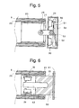
- Figure 6 is a similar view showing a fifth mode of execution.
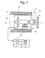
- FIG. 7 represents an alternative embodiment of the first embodiment equipped with a device interruption of power of a different type.
- FIG. 1 we recognize a box 1 in which wraps a rolling shutter 2 around a tube winding driven by a tubular motor housed at the inside of the winding tube according to a well known construction and supplied with low voltage BT through a control box 3 provided with push buttons for controlling the winding and rolling shutter sequence 2.
- the box is mounted fixed in a doorway not shown and its ends are closed by two cheeks 4 and 5 supporting the motor and bearings of the winding tube.
- the weight of the motor assembly, winding tube and flap is distributed on the two cheeks 4 and 5 of the box. he is therefore possible to detect a change in weight apparent from this set either to one or the other of its ends, either at both ends at the same time.
- FIG. 2 represents a first embodiment of the support of the left end of the rollable product.
- a winding tube 6 inside which is mounted a tubular casing 20 constituted by the extension of the casing of a tubular motor not represented.
- This housing 20 is fixed on and around a support 23 in the form of a cylindrical sleeve, one of which bearing form part for an annular end piece 21 integral with the winding tube 6.
- the sleeve 23 is supported by the cheek 4 of the box through a rigid arm 24 articulated, on the one hand, at a point intermediate, around a horizontal axis 25, on the sleeve 23 and, on the other hand, by its end outside, around a second horizontal axis 31 on a console 26 secured to the cheek 4.
- the part of the weight of the rollable product acting on the axis 25, which we will simply call product weight subsequently retractable is compensated by a spring 28 working in compression between arm 24 and a crosspiece or console 22 of the sleeve 23.
- the weight of the rollable product is compensated in such a way that the arm 24 is in the horizontal position shown in the drawing.
- the sleeve 23 are in in addition to two switches 29 and 30, the first being located below arm 24 and the second in above the arm 24 opposite the first.
- the operation of the automatic shutdown device is the following :
- the stop device according to the invention operates from particularly satisfactorily in the event that the rollable product is fitted with locking means pushing down on the apron of the roller shutter when it is fully extended so as to prevent unauthorized opening of the roller shutter by lifting it by its terminal blade.
- locking means are described, for example, in patents FR 2,398,870 and FR 2 584 130.
- the reaction of the shutter support can, in this case, practically cancel the weight visible of the rollable product, which provides a very high operational safety of the stop in unrolled position.
- a necessary condition and, well understood, that the rollable product has a buckling resistance in the unrolled position. It's the roller shutters and blinds with guided slats in rails or slides.
- the embodiment shown in Figure 3 does not differ of the first mode of execution than by the link mode from the rigid arm 24 to the fixed support 4 and by the position of the switch 30.
- the outer end of the arm 24 is simply fitted with play in the fixed support 4, this clearance being sufficient to allow tilting of arm 24 necessary for the actuation of one or the other of switches 29 and 30.
- the two switches 29 and 30 are located below the arm 24, on either side of axis 25, the arm being horizontal when it supports the weight of the deck plus friction, when climbing.
- the switch 30 could however be placed above of the arm 24, as shown in 30 '.
- the rollable product is supported by an arm flexible 32 whose outer end is fixed by recess in the support 4.
- This arm 32 is articulated at an intermediate point around an axis 25 on the support 23.
- switch 29 When the apparent weight increases, arm 32 flexes down and actuates switch 29.
- arm 32 discharged, straightens towards the high.
- the winding tube rises and the switch 30 comes to meet arm 32.
- switch 30 could be placed above arm 32, opposite the switch 29.
- the switches 29 and 30 are mounted in a fixed support 54 in the shape of a box.
- the sleeve 23 is supported by a T-shaped arm 51 whose leg is articulated by its lower end on the sleeve 23 around an axis 25 and by its other end, constituting the intermediate point of the arm, on the fixed support 54 around an axis 53.
- the rigid arm 51 is therefore articulated, by one end, on the means winding, around a first axis and at a point intermediate on the fixed support, around a second axis.
- the weight compensation acting on axis 25 is provided by a hunting horn spring 52 mounted around axis 53 and leaning on one side on the fixed support 54 and on the other side on a nipple 50 of the bar transverse of the arm in T 51.
- the functioning of this execution mode is identical to that of mode shown in Figure 2.
- the spring 28 could be replaced by a spring working in traction or any other elastic means working in compression or traction.
- the embodiment shown in Figure 6 is distinguishes from previous execution modes by the absence of a materialized articulation axis.
- a cylinder 60 in elastomer over about half of its length this elastomer cylinder being fixed by its base external to a fixed support 61.
- a bar 62 in the cylinder in elastomeric material 60 is embedded a bar 62 on about half of its length.
- the weight applied by the product that can be rolled up on the elastomer block 60 has the effect of creating stresses in the elastomer decreasing from the shear zone, at its connection to the support 61, towards its end interior.
- the apparent weight changes the decrease of these constraints has the effect of change the orientation of arm 62, as if it pivoted around a virtual axis. This pivoting operates switches 29 and 30 as in the first mode of execution.
- switches 29 and 30 can be replaced by another type of power interruption device.
- An example is illustrated in Figure 7.
- FIG. 7 resumes the mechanical elements of the first embodiment shown in Figure 2.
- Switches 29 and 30 are replaced by a slider potentiometer 70 associated with electronics 71 comprising an interface I / O, one ULT (logical processing unit), two ROM and RAM memories and an H clock.
- the arm 24 drives the cursor 72 of the potentiometer.
- a relocation determined from cursor 72 up or down a the effect of causing the interruption of the power supply of the motor to the unwinding, respectively to the winding.
Landscapes
- Engineering & Computer Science (AREA)
- Structural Engineering (AREA)
- Architecture (AREA)
- Civil Engineering (AREA)
- Operating, Guiding And Securing Of Roll- Type Closing Members (AREA)
- Maintenance And Inspection Apparatuses For Elevators (AREA)
- Looms (AREA)
- Controlling Rewinding, Feeding, Winding, Or Abnormalities Of Webs (AREA)
- Blinds (AREA)
- Finish Polishing, Edge Sharpening, And Grinding By Specific Grinding Devices (AREA)
- Electric Ovens (AREA)
Applications Claiming Priority (2)
| Application Number | Priority Date | Filing Date | Title |
|---|---|---|---|
| FR9705280A FR2762643B1 (fr) | 1997-04-29 | 1997-04-29 | Produit enroulable motorise equipe d'un dispositif d'arret sensible a une variation de poids |
| FR9705280 | 1997-04-29 |
Publications (2)
| Publication Number | Publication Date |
|---|---|
| EP0875656A1 true EP0875656A1 (de) | 1998-11-04 |
| EP0875656B1 EP0875656B1 (de) | 2003-06-04 |
Family
ID=9506418
Family Applications (1)
| Application Number | Title | Priority Date | Filing Date |
|---|---|---|---|
| EP98810278A Expired - Lifetime EP0875656B1 (de) | 1997-04-29 | 1998-03-31 | Aufrollbares motorisiertes Produkt, welches mit einer Stopvorrichtung ausgerüstet ist, die eine Gewichtsveränderung erfasst |
Country Status (5)
| Country | Link |
|---|---|
| EP (1) | EP0875656B1 (de) |
| AT (1) | ATE242414T1 (de) |
| DE (1) | DE69815205T2 (de) |
| ES (1) | ES2124683T3 (de) |
| FR (1) | FR2762643B1 (de) |
Families Citing this family (1)
| Publication number | Priority date | Publication date | Assignee | Title |
|---|---|---|---|---|
| DE202009006587U1 (de) * | 2009-03-04 | 2010-07-22 | Marantec Antriebs- Und Steuerungstechnik Gmbh & Co. Kg | Torantrieb mit zwei Motoren |
Citations (7)
| Publication number | Priority date | Publication date | Assignee | Title |
|---|---|---|---|---|
| FR2398870A1 (fr) | 1977-07-25 | 1979-02-23 | Alberts Gmbh & Co Kg G | Dispositif de verrouillage de volets et portes roulantes |
| FR2584130A1 (fr) | 1985-06-28 | 1987-01-02 | Schlagmuller Paul | Volet roulant de protection pour ouvertures dans les murs |
| DE3925625A1 (de) | 1989-07-31 | 1991-02-14 | Schleicher Relais | Getaktete konstantleistungsquelle mit hohem wirkungsgrad und grossem eingangsspannungsbereich |
| EP0703344A1 (de) * | 1994-09-22 | 1996-03-27 | Gottlieb Klenk | Vorrichtung zur selbsttätigen Endabschaltung eines Rollvorhangs, insbesondere eines Rollandenpanzers |
| DE4445978A1 (de) * | 1994-12-22 | 1996-06-27 | Wiral Rolladenfertigungs Und V | Verfahren und Steuervorrichtung zur Betätigung einer Sicherungseinrichtung an Rolltoren oder Rolladen |
| WO1996022446A1 (en) | 1995-01-18 | 1996-07-25 | V. Kann Rasmussen Industri A/S | An end stop device for an electrically operated window screening arrangement |
| DE19610877A1 (de) * | 1995-06-30 | 1997-01-02 | Becker Antriebe Gmbh | Vorrichtung zur Steuerung eines Antriebes für Rolläden, Rolltore o. dgl. |
-
1997
- 1997-04-29 FR FR9705280A patent/FR2762643B1/fr not_active Expired - Lifetime
-
1998
- 1998-03-31 AT AT98810278T patent/ATE242414T1/de not_active IP Right Cessation
- 1998-03-31 DE DE69815205T patent/DE69815205T2/de not_active Expired - Fee Related
- 1998-03-31 EP EP98810278A patent/EP0875656B1/de not_active Expired - Lifetime
- 1998-03-31 ES ES98810278T patent/ES2124683T3/es not_active Expired - Lifetime
Patent Citations (7)
| Publication number | Priority date | Publication date | Assignee | Title |
|---|---|---|---|---|
| FR2398870A1 (fr) | 1977-07-25 | 1979-02-23 | Alberts Gmbh & Co Kg G | Dispositif de verrouillage de volets et portes roulantes |
| FR2584130A1 (fr) | 1985-06-28 | 1987-01-02 | Schlagmuller Paul | Volet roulant de protection pour ouvertures dans les murs |
| DE3925625A1 (de) | 1989-07-31 | 1991-02-14 | Schleicher Relais | Getaktete konstantleistungsquelle mit hohem wirkungsgrad und grossem eingangsspannungsbereich |
| EP0703344A1 (de) * | 1994-09-22 | 1996-03-27 | Gottlieb Klenk | Vorrichtung zur selbsttätigen Endabschaltung eines Rollvorhangs, insbesondere eines Rollandenpanzers |
| DE4445978A1 (de) * | 1994-12-22 | 1996-06-27 | Wiral Rolladenfertigungs Und V | Verfahren und Steuervorrichtung zur Betätigung einer Sicherungseinrichtung an Rolltoren oder Rolladen |
| WO1996022446A1 (en) | 1995-01-18 | 1996-07-25 | V. Kann Rasmussen Industri A/S | An end stop device for an electrically operated window screening arrangement |
| DE19610877A1 (de) * | 1995-06-30 | 1997-01-02 | Becker Antriebe Gmbh | Vorrichtung zur Steuerung eines Antriebes für Rolläden, Rolltore o. dgl. |
Also Published As
| Publication number | Publication date |
|---|---|
| DE69815205D1 (de) | 2003-07-10 |
| EP0875656B1 (de) | 2003-06-04 |
| ES2124683T1 (es) | 1999-02-16 |
| FR2762643A1 (fr) | 1998-10-30 |
| ATE242414T1 (de) | 2003-06-15 |
| FR2762643B1 (fr) | 1999-07-02 |
| DE69815205T2 (de) | 2004-04-15 |
| ES2124683T3 (es) | 2004-04-01 |
Similar Documents
| Publication | Publication Date | Title |
|---|---|---|
| EP0014112B1 (de) | Schiebetür für Notöffnung | |
| FR2628619A1 (fr) | Lit a mecanisme elevateur | |
| EP0453359B1 (de) | Anzeigetafel, insbesondere geeignet für eine erhöhte Lage | |
| EP0936342B1 (de) | Steuerungsvorrichtung eines Elektomotors, der ein Teil antreibt | |
| EP0751278B1 (de) | Motorisierter Rolladen | |
| EP0497711B1 (de) | Sicherungseinrichtung für elektrische Betätigungseinrichtung für Rolläden | |
| EP0875656B1 (de) | Aufrollbares motorisiertes Produkt, welches mit einer Stopvorrichtung ausgerüstet ist, die eine Gewichtsveränderung erfasst | |
| FR2671372A1 (fr) | Dispositif de commande d'ouverture d'un ouvrant relie a un dormant pour assurer, d'une part, l'aeration et, d'autre part, l'evacuation rapide des fumees et de la chaleur d'un batiment. | |
| EP0819204B1 (de) | Hubtor mit sicherheitssystem | |
| EP0844362B1 (de) | Vorrichtung zum automatischen Abschalten eines Motorantriebes einer Rolladenwickelwelle | |
| EP0480540A2 (de) | Flexible aufrollbare Tür | |
| FR2740824A1 (fr) | Installation de fermeture ou de protection solaire motorisee | |
| FR2819545A1 (fr) | Volet roulant pourvu d'un dispositif de detection d'obstacle | |
| EP3470616B1 (de) | Verfahren zur automatischen regulierung einer mit einem blockiersystem ausgestatteten rollladenanlage | |
| EP0908593B1 (de) | Motorgetriebene Rolläden | |
| EP1844210A1 (de) | Vorrichtung zum bremsen der drehung der antriebswelle eines blattes einer hochgeschwindigkeitstür | |
| EP1427908A1 (de) | Elastische kupplung zur ausrichtung der drehwinkelstellung zweier teile | |
| EP0844363B1 (de) | Antriebsvorrichtung für Rolladen oder dergleichen | |
| EP1612360A1 (de) | Steuervorrichtung eines motorischen Schiebefensters, insbesondere für eine Fahrerkabine von Eisenbahnmaterial oder dergleichen | |
| EP0866207A1 (de) | Mit einer motorisierten Verdunkelungseinrichtung ausgerüstetes Rahmenbauteil | |
| FR2493906A1 (fr) | Volet roulant ou dispositif similaire avec entrainement electrique et commande automatique | |
| WO2000049264A1 (fr) | Dispositif pour arreter en fonction d'un couple de declenchement variable, un moteur entrainant un tube d'enroulement d'un volet roulant | |
| EP3190253B1 (de) | Dreh-kippfenster für ein gebäude, und hausanlage, die ein solches dreh-kippfenster umfasst | |
| EP2397645A1 (de) | Mono-gesteuerte motorisch angetriebene Jalousie | |
| FR2743842A1 (fr) | Dispositif de securite pour le rideau de portes relevables |
Legal Events
| Date | Code | Title | Description |
|---|---|---|---|
| PUAI | Public reference made under article 153(3) epc to a published international application that has entered the european phase |
Free format text: ORIGINAL CODE: 0009012 |
|
| AK | Designated contracting states |
Kind code of ref document: A1 Designated state(s): AT BE CH DE ES GB IT LI NL SE |
|
| AX | Request for extension of the european patent |
Free format text: AL;LT;LV;MK;RO;SI |
|
| REG | Reference to a national code |
Ref country code: ES Ref legal event code: BA2A Ref document number: 2124683 Country of ref document: ES Kind code of ref document: T1 |
|
| 17P | Request for examination filed |
Effective date: 19990318 |
|
| AKX | Designation fees paid |
Free format text: AT BE CH DE ES GB IT LI NL SE |
|
| GRAH | Despatch of communication of intention to grant a patent |
Free format text: ORIGINAL CODE: EPIDOS IGRA |
|
| GRAH | Despatch of communication of intention to grant a patent |
Free format text: ORIGINAL CODE: EPIDOS IGRA |
|
| GRAA | (expected) grant |
Free format text: ORIGINAL CODE: 0009210 |
|
| AK | Designated contracting states |
Designated state(s): AT BE CH DE ES GB IT LI NL SE |
|
| PG25 | Lapsed in a contracting state [announced via postgrant information from national office to epo] |
Ref country code: NL Free format text: LAPSE BECAUSE OF FAILURE TO SUBMIT A TRANSLATION OF THE DESCRIPTION OR TO PAY THE FEE WITHIN THE PRESCRIBED TIME-LIMIT Effective date: 20030604 Ref country code: GB Free format text: LAPSE BECAUSE OF FAILURE TO SUBMIT A TRANSLATION OF THE DESCRIPTION OR TO PAY THE FEE WITHIN THE PRESCRIBED TIME-LIMIT Effective date: 20030604 Ref country code: AT Free format text: LAPSE BECAUSE OF FAILURE TO SUBMIT A TRANSLATION OF THE DESCRIPTION OR TO PAY THE FEE WITHIN THE PRESCRIBED TIME-LIMIT Effective date: 20030604 |
|
| REG | Reference to a national code |
Ref country code: GB Ref legal event code: FG4D Free format text: NOT ENGLISH |
|
| REG | Reference to a national code |
Ref country code: CH Ref legal event code: EP |
|
| REF | Corresponds to: |
Ref document number: 69815205 Country of ref document: DE Date of ref document: 20030710 Kind code of ref document: P |
|
| PG25 | Lapsed in a contracting state [announced via postgrant information from national office to epo] |
Ref country code: SE Free format text: LAPSE BECAUSE OF FAILURE TO SUBMIT A TRANSLATION OF THE DESCRIPTION OR TO PAY THE FEE WITHIN THE PRESCRIBED TIME-LIMIT Effective date: 20030904 |
|
| NLV1 | Nl: lapsed or annulled due to failure to fulfill the requirements of art. 29p and 29m of the patents act | ||
| GBV | Gb: ep patent (uk) treated as always having been void in accordance with gb section 77(7)/1977 [no translation filed] |
Effective date: 20030604 |
|
| PGFP | Annual fee paid to national office [announced via postgrant information from national office to epo] |
Ref country code: DE Payment date: 20040316 Year of fee payment: 7 |
|
| PGFP | Annual fee paid to national office [announced via postgrant information from national office to epo] |
Ref country code: ES Payment date: 20040318 Year of fee payment: 7 |
|
| PG25 | Lapsed in a contracting state [announced via postgrant information from national office to epo] |
Ref country code: LI Free format text: LAPSE BECAUSE OF NON-PAYMENT OF DUE FEES Effective date: 20040331 Ref country code: CH Free format text: LAPSE BECAUSE OF NON-PAYMENT OF DUE FEES Effective date: 20040331 Ref country code: BE Free format text: LAPSE BECAUSE OF NON-PAYMENT OF DUE FEES Effective date: 20040331 |
|
| REG | Reference to a national code |
Ref country code: ES Ref legal event code: FG2A Ref document number: 2124683 Country of ref document: ES Kind code of ref document: T3 |
|
| PLBE | No opposition filed within time limit |
Free format text: ORIGINAL CODE: 0009261 |
|
| STAA | Information on the status of an ep patent application or granted ep patent |
Free format text: STATUS: NO OPPOSITION FILED WITHIN TIME LIMIT |
|
| 26N | No opposition filed |
Effective date: 20040305 |
|
| BERE | Be: lapsed |
Owner name: *SIMU Effective date: 20040331 |
|
| REG | Reference to a national code |
Ref country code: CH Ref legal event code: PL |
|
| PG25 | Lapsed in a contracting state [announced via postgrant information from national office to epo] |
Ref country code: IT Free format text: LAPSE BECAUSE OF NON-PAYMENT OF DUE FEES Effective date: 20050331 |
|
| PG25 | Lapsed in a contracting state [announced via postgrant information from national office to epo] |
Ref country code: ES Free format text: LAPSE BECAUSE OF NON-PAYMENT OF DUE FEES Effective date: 20050401 |
|
| PG25 | Lapsed in a contracting state [announced via postgrant information from national office to epo] |
Ref country code: DE Free format text: LAPSE BECAUSE OF NON-PAYMENT OF DUE FEES Effective date: 20051001 |
|
| REG | Reference to a national code |
Ref country code: ES Ref legal event code: FD2A Effective date: 20050401 |