EP0875656A1 - Rollable motorised product equipped with a stop device which is sensitive to a weight variation - Google Patents
Rollable motorised product equipped with a stop device which is sensitive to a weight variation Download PDFInfo
- Publication number
- EP0875656A1 EP0875656A1 EP98810278A EP98810278A EP0875656A1 EP 0875656 A1 EP0875656 A1 EP 0875656A1 EP 98810278 A EP98810278 A EP 98810278A EP 98810278 A EP98810278 A EP 98810278A EP 0875656 A1 EP0875656 A1 EP 0875656A1
- Authority
- EP
- European Patent Office
- Prior art keywords
- winding
- arm
- rollable
- product according
- fixed support
- Prior art date
- Legal status (The legal status is an assumption and is not a legal conclusion. Google has not performed a legal analysis and makes no representation as to the accuracy of the status listed.)
- Granted
Links
Images


Classifications
-
- E—FIXED CONSTRUCTIONS
- E06—DOORS, WINDOWS, SHUTTERS, OR ROLLER BLINDS IN GENERAL; LADDERS
- E06B—FIXED OR MOVABLE CLOSURES FOR OPENINGS IN BUILDINGS, VEHICLES, FENCES OR LIKE ENCLOSURES IN GENERAL, e.g. DOORS, WINDOWS, BLINDS, GATES
- E06B9/00—Screening or protective devices for wall or similar openings, with or without operating or securing mechanisms; Closures of similar construction
- E06B9/56—Operating, guiding or securing devices or arrangements for roll-type closures; Spring drums; Tape drums; Counterweighting arrangements therefor
- E06B9/80—Safety measures against dropping or unauthorised opening; Braking or immobilising devices; Devices for limiting unrolling
- E06B9/82—Safety measures against dropping or unauthorised opening; Braking or immobilising devices; Devices for limiting unrolling automatic
- E06B9/88—Safety measures against dropping or unauthorised opening; Braking or immobilising devices; Devices for limiting unrolling automatic for limiting unrolling
-
- E—FIXED CONSTRUCTIONS
- E06—DOORS, WINDOWS, SHUTTERS, OR ROLLER BLINDS IN GENERAL; LADDERS
- E06B—FIXED OR MOVABLE CLOSURES FOR OPENINGS IN BUILDINGS, VEHICLES, FENCES OR LIKE ENCLOSURES IN GENERAL, e.g. DOORS, WINDOWS, BLINDS, GATES
- E06B9/00—Screening or protective devices for wall or similar openings, with or without operating or securing mechanisms; Closures of similar construction
- E06B9/56—Operating, guiding or securing devices or arrangements for roll-type closures; Spring drums; Tape drums; Counterweighting arrangements therefor
- E06B9/68—Operating devices or mechanisms, e.g. with electric drive
- E06B2009/6809—Control
- E06B2009/6818—Control using sensors
- E06B2009/6854—Control using sensors sensing torque
Definitions
- the invention relates to a motorized windable product.
- a motorized windable product comprising winding means driven by a electric motor and equipped with a stop device automatic operating by detecting a variation of the apparent weight, at at least one support point, of the rollable product, and comprising at least one power interruption device activated by moving the winding means and a means elastic to compensate for the apparent weight of the product can be rolled up in a partially unrolled position.
- the object of the present invention is to provide a particularly compact and clean construction used in all motorized winding products, in especially motorized roll-up products comprising a winding tube.
- This construction must also be easily adaptable to ensure automatic shutdown both in the rolled up position and in the unfolded.
- the rollable product according to the invention is characterized in that the winding means are supported at at least one of their ends by a connected arm, on the one hand, to the winding means and, on the other hand, to a fixed support, so that its orientation varies with the apparent weight and in that this arm simultaneously constitutes an actuator of the power interruption device.
- the arm can be rigid and articulated by one end on the fixed support and at an intermediate point on the winding means, the elastic means of compensation consisting of a spring opposing the rotation of the arm, this spring being able to be mounted in the winding means, in particular in the tube winding, or in the fixed support.
- the arm can consist of a fixed flexible bar by embedding in the fixed support and articulated in an intermediate point on the winding means.
- a rigid arm is embedded, by a significant part of its length, in an elastomer block supporting the winding means and one end of which is fixed to the fixed support, to a certain distance from the winding means, such so that the force exerted on the elastomer by the apparent weight of the rollable product has the effect to generate constraints in the elastomer decreasing from its bond to the support, from so that the variation in the apparent weight is translated by the modification of the orientation of said arm and actuation of a device for interrupting food.
- the power interruption device can be made up of a mechanical switch under its simplest form or more complex device, such as an encoder, for example a potentiometer, associated to electronics.
- Figure 1 shows schematically a rolling shutter partially unfolded.
- Figure 2 is an axial sectional view of one end of the roller tube of the roller shutter of Figure 1 according to a first embodiment.
- Figure 3 is a view similar to Figure 2 representing a second embodiment.
- Figure 4 is a similar view showing a third embodiment.
- Figure 5 is a similar view showing a fourth embodiment.
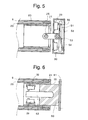
- Figure 6 is a similar view showing a fifth mode of execution.
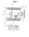
- FIG. 7 represents an alternative embodiment of the first embodiment equipped with a device interruption of power of a different type.
- FIG. 1 we recognize a box 1 in which wraps a rolling shutter 2 around a tube winding driven by a tubular motor housed at the inside of the winding tube according to a well known construction and supplied with low voltage BT through a control box 3 provided with push buttons for controlling the winding and rolling shutter sequence 2.
- the box is mounted fixed in a doorway not shown and its ends are closed by two cheeks 4 and 5 supporting the motor and bearings of the winding tube.
- the weight of the motor assembly, winding tube and flap is distributed on the two cheeks 4 and 5 of the box. he is therefore possible to detect a change in weight apparent from this set either to one or the other of its ends, either at both ends at the same time.
- FIG. 2 represents a first embodiment of the support of the left end of the rollable product.
- a winding tube 6 inside which is mounted a tubular casing 20 constituted by the extension of the casing of a tubular motor not represented.
- This housing 20 is fixed on and around a support 23 in the form of a cylindrical sleeve, one of which bearing form part for an annular end piece 21 integral with the winding tube 6.
- the sleeve 23 is supported by the cheek 4 of the box through a rigid arm 24 articulated, on the one hand, at a point intermediate, around a horizontal axis 25, on the sleeve 23 and, on the other hand, by its end outside, around a second horizontal axis 31 on a console 26 secured to the cheek 4.
- the part of the weight of the rollable product acting on the axis 25, which we will simply call product weight subsequently retractable is compensated by a spring 28 working in compression between arm 24 and a crosspiece or console 22 of the sleeve 23.
- the weight of the rollable product is compensated in such a way that the arm 24 is in the horizontal position shown in the drawing.
- the sleeve 23 are in in addition to two switches 29 and 30, the first being located below arm 24 and the second in above the arm 24 opposite the first.
- the operation of the automatic shutdown device is the following :
- the stop device according to the invention operates from particularly satisfactorily in the event that the rollable product is fitted with locking means pushing down on the apron of the roller shutter when it is fully extended so as to prevent unauthorized opening of the roller shutter by lifting it by its terminal blade.
- locking means are described, for example, in patents FR 2,398,870 and FR 2 584 130.
- the reaction of the shutter support can, in this case, practically cancel the weight visible of the rollable product, which provides a very high operational safety of the stop in unrolled position.
- a necessary condition and, well understood, that the rollable product has a buckling resistance in the unrolled position. It's the roller shutters and blinds with guided slats in rails or slides.
- the embodiment shown in Figure 3 does not differ of the first mode of execution than by the link mode from the rigid arm 24 to the fixed support 4 and by the position of the switch 30.
- the outer end of the arm 24 is simply fitted with play in the fixed support 4, this clearance being sufficient to allow tilting of arm 24 necessary for the actuation of one or the other of switches 29 and 30.
- the two switches 29 and 30 are located below the arm 24, on either side of axis 25, the arm being horizontal when it supports the weight of the deck plus friction, when climbing.
- the switch 30 could however be placed above of the arm 24, as shown in 30 '.
- the rollable product is supported by an arm flexible 32 whose outer end is fixed by recess in the support 4.
- This arm 32 is articulated at an intermediate point around an axis 25 on the support 23.
- switch 29 When the apparent weight increases, arm 32 flexes down and actuates switch 29.
- arm 32 discharged, straightens towards the high.
- the winding tube rises and the switch 30 comes to meet arm 32.
- switch 30 could be placed above arm 32, opposite the switch 29.
- the switches 29 and 30 are mounted in a fixed support 54 in the shape of a box.
- the sleeve 23 is supported by a T-shaped arm 51 whose leg is articulated by its lower end on the sleeve 23 around an axis 25 and by its other end, constituting the intermediate point of the arm, on the fixed support 54 around an axis 53.
- the rigid arm 51 is therefore articulated, by one end, on the means winding, around a first axis and at a point intermediate on the fixed support, around a second axis.
- the weight compensation acting on axis 25 is provided by a hunting horn spring 52 mounted around axis 53 and leaning on one side on the fixed support 54 and on the other side on a nipple 50 of the bar transverse of the arm in T 51.
- the functioning of this execution mode is identical to that of mode shown in Figure 2.
- the spring 28 could be replaced by a spring working in traction or any other elastic means working in compression or traction.
- the embodiment shown in Figure 6 is distinguishes from previous execution modes by the absence of a materialized articulation axis.
- a cylinder 60 in elastomer over about half of its length this elastomer cylinder being fixed by its base external to a fixed support 61.
- a bar 62 in the cylinder in elastomeric material 60 is embedded a bar 62 on about half of its length.
- the weight applied by the product that can be rolled up on the elastomer block 60 has the effect of creating stresses in the elastomer decreasing from the shear zone, at its connection to the support 61, towards its end interior.
- the apparent weight changes the decrease of these constraints has the effect of change the orientation of arm 62, as if it pivoted around a virtual axis. This pivoting operates switches 29 and 30 as in the first mode of execution.
- switches 29 and 30 can be replaced by another type of power interruption device.
- An example is illustrated in Figure 7.
- FIG. 7 resumes the mechanical elements of the first embodiment shown in Figure 2.
- Switches 29 and 30 are replaced by a slider potentiometer 70 associated with electronics 71 comprising an interface I / O, one ULT (logical processing unit), two ROM and RAM memories and an H clock.
- the arm 24 drives the cursor 72 of the potentiometer.
- a relocation determined from cursor 72 up or down a the effect of causing the interruption of the power supply of the motor to the unwinding, respectively to the winding.
Landscapes
- Engineering & Computer Science (AREA)
- Structural Engineering (AREA)
- Architecture (AREA)
- Civil Engineering (AREA)
- Operating, Guiding And Securing Of Roll- Type Closing Members (AREA)
- Maintenance And Inspection Apparatuses For Elevators (AREA)
- Looms (AREA)
- Controlling Rewinding, Feeding, Winding, Or Abnormalities Of Webs (AREA)
- Electric Ovens (AREA)
- Finish Polishing, Edge Sharpening, And Grinding By Specific Grinding Devices (AREA)
- Blinds (AREA)
Abstract
Description
L'invention concerne un produit enroulable motorisé comprenant des moyens d'enroulement entraínés par un moteur électrique et équipé d'un dispositif d'arrêt automatique opérant par la détection d'une variation du poids apparent, en au moins un point de soutien, du produit enroulable, et comprenant au moins un dispositif d'interruption de l'alimentation actionné par le déplacement des moyens d'enroulement et un moyen élastique de compensation du poids apparent du produit enroulable dans une position partiellement déroulée.The invention relates to a motorized windable product. comprising winding means driven by a electric motor and equipped with a stop device automatic operating by detecting a variation of the apparent weight, at at least one support point, of the rollable product, and comprising at least one power interruption device activated by moving the winding means and a means elastic to compensate for the apparent weight of the product can be rolled up in a partially unrolled position.
L'utilisation de la variation du poids apparent d'un store muni d'une barre de charge pour son arrêt en position déroulée est décrite dans la demande de brevet internationale WO 96/22446. La brusque diminution du poids apparent du store lorsque sa barre de charge vient reposer au bas de la fenêtre en position complètement déroulée a pour effet d'autoriser un ressort de compensation à relever obliquement l'arbre d'enroulement, ce relèvement ayant pour effet d'ouvrir un interrupteur et de couper ainsi l'alimentation du moteur.The use of variation in the apparent weight of a awning with a load bar for stopping it unrolled position is described in the patent application international WO 96/22446. The abrupt decrease in apparent weight of the awning when its load bar comes to rest at the bottom of the window in position completely unrolled has the effect of authorizing a compensation spring to tilt the shaft obliquely winding, this raising having the effect of opening switch and cut off the power to the engine.
De la demande de brevet DE 39 25 625, on connaít
d'autre part un dispositif d'arrêt automatique du
moteur d'entraínement d'un rideau muni d'une barre de
charge, utilisant la variation du poids apparent du
rideau pour arrêter le déroulement de celui-ci lorsque
la barre de charge rencontre un obstacle lors de son
déroulement.
La compensation du poids du rideau est assurée par des
poids suspendus dont la descente actionne des
interrupteurs. From patent application DE 39 25 625, there is also known an automatic shutdown device for the motor driving a curtain fitted with a load bar, using the variation in the apparent weight of the curtain to stop the unfolding thereof when the load bar encounters an obstacle during its unfolding.
The weight of the curtain is compensated by suspended weights, the descent of which activates switches.
L'utilisation de la variation du poids apparent du produit enroulable pour assurer son arrêt en position déroulée permet d'obtenir un dispositif d'arrêt très sûr, sensible et ne nécessitant aucun réglage fonction de la course du produit enroulable.The use of the variation in the apparent weight of the rollable product to ensure it stops in position unrolled provides a very stop device safe, sensitive and requires no function adjustment of the travel of the rollable product.
La présente invention a pour but de réaliser une construction particulièrement compacte et propre à être utilisée dans tous produits enroulables motorisés, en particulier les produits enroulables motorisés comportant un tube d'enroulement.The object of the present invention is to provide a particularly compact and clean construction used in all motorized winding products, in especially motorized roll-up products comprising a winding tube.
Cette construction doit en outre être aisément adaptable de manière à assurer un arrêt automatique aussi bien en position enroulée, qu'en position déroulée.This construction must also be easily adaptable to ensure automatic shutdown both in the rolled up position and in the unfolded.
Le produit enroulable selon l'invention est caractérisé en ce que les moyens d'enroulement sont supportés à l'une au moins de leurs extrémités par un bras relié, d'une part, aux moyens d'enroulement et, d'autre part, à un support fixe, de telle manière que son orientation varie avec le poids apparent et en ce que ce bras constitue simultanément un organe d'actionnement du dispositif d'interruption de l'alimentation.The rollable product according to the invention is characterized in that the winding means are supported at at least one of their ends by a connected arm, on the one hand, to the winding means and, on the other hand, to a fixed support, so that its orientation varies with the apparent weight and in that this arm simultaneously constitutes an actuator of the power interruption device.
Le bras peut être rigide et articulé par une extrémité sur le support fixe et en un point intermédiaire sur les moyens d'enroulement, le moyen élastique de compensation étant constitué d'un ressort s'opposant à la rotation du bras, ce ressort pouvant être monté dans les moyens d'enroulement, en particulier dans le tube d'enroulement, ou dans le support fixe.The arm can be rigid and articulated by one end on the fixed support and at an intermediate point on the winding means, the elastic means of compensation consisting of a spring opposing the rotation of the arm, this spring being able to be mounted in the winding means, in particular in the tube winding, or in the fixed support.
Le bras peut être constitué d'une barre flexible fixée par encastrement dans le support fixe et articulée en un point intermédiaire sur les moyens d'enroulement.The arm can consist of a fixed flexible bar by embedding in the fixed support and articulated in an intermediate point on the winding means.
Selon un autre mode d'exécution, un bras rigide est encastré, par une partie important de sa longueur, dans un bloc élastomère supportant les moyens d'enroulement et dont une extrémité est fixée au support fixe, à une certaine distance des moyens d'enroulement, de telle manière que l'effort exercé sur l'élastomère par le poids apparent du produit enroulable a pour effet d'engendrer dans l'élastomère des contraintes décroissantes à partir de sa liaison au support, de telle sorte que la variation du poids apparent se traduit par la modification de l'orientation dudit bras et l'actionnement d'un dispositif d'interruption de l'alimentation.According to another embodiment, a rigid arm is embedded, by a significant part of its length, in an elastomer block supporting the winding means and one end of which is fixed to the fixed support, to a certain distance from the winding means, such so that the force exerted on the elastomer by the apparent weight of the rollable product has the effect to generate constraints in the elastomer decreasing from its bond to the support, from so that the variation in the apparent weight is translated by the modification of the orientation of said arm and actuation of a device for interrupting food.
Le dispositif d'interruption de l'alimentation peut être constitué d'un interrupteur mécanique sous sa forme la plus simple ou d'un dispositif plus complexe, tel qu'un codeur, par exemple un potentiomètre, associé à une électronique.The power interruption device can be made up of a mechanical switch under its simplest form or more complex device, such as an encoder, for example a potentiometer, associated to electronics.
Le dessin annexé représente, à titre d'exemple, quelques modes d'exécution du produit enroulable motorisé selon l'invention.The accompanying drawing shows, by way of example, some execution modes of the rollable product motorized according to the invention.
La figure 1 représente schématiquement un volet roulant partiellement déroulé. Figure 1 shows schematically a rolling shutter partially unfolded.
La figure 2 est une vue en coupe axiale d'une extrémité du tube d'enroulement du volet roulant de la figure 1 selon un premier mode d'exécution.Figure 2 is an axial sectional view of one end of the roller tube of the roller shutter of Figure 1 according to a first embodiment.
La figure 3 est une vue analogue à la figure 2 représentant un deuxième mode d'exécution.Figure 3 is a view similar to Figure 2 representing a second embodiment.
La figure 4 est une vue analogue représentant un troisième mode d'exécution.Figure 4 is a similar view showing a third embodiment.
La figure 5 est une vue analogue représentant un quatrième mode d'exécution.Figure 5 is a similar view showing a fourth embodiment.
La figure 6 est une vue analogue représentant un cinquième mode d'exécution.Figure 6 is a similar view showing a fifth mode of execution.
La figure 7 représente une variante d'exécution du premier mode d'exécution équipé d'un dispositif d'interruption de l'alimentation d'un type différent.FIG. 7 represents an alternative embodiment of the first embodiment equipped with a device interruption of power of a different type.
A la figure 1, on reconnaít un caisson 1 dans lequel
vient s'enrouler un volet roulant 2 autour d'un tube
d'enroulement entraíné par un moteur tubulaire logé à
l'intérieur du tube d'enroulement selon une
construction bien connue et alimenté en basse tension
BT à travers un boítier de commande 3 muni de boutons-poussoirs
pour la commande de l'enroulement et du
déroulement du volet roulant 2. Le caisson est monté
fixe dans une embrasure non représentée et ses
extrémités sont fermées par deux joues 4 et 5 soutenant
le moteur et les paliers du tube d'enroulement. Le
poids de l'ensemble moteur, tube d'enroulement et volet
se répartit sur les deux joues 4 et 5 du caisson. Il
est donc possible de détecter une variation de poids
apparent de cet ensemble soit à l'une ou l'autre de ses
extrémités, soit aux deux extrémités à la fois.In Figure 1, we recognize a
La figure 2 représente un premier mode d'exécution du
soutien de l'extrémité gauche du produit enroulable. On
distingue un tube d'enroulement 6 à l'intérieur duquel
est monté un carter tubulaire 20 constitué par le
prolongement du carter d'un moteur tubulaire non
représenté. Ce carter 20 est fixé sur et autour d'un
support 23 en forme de manchon cylindrique dont une
partie forme palier pour un embout annulaire 21
solidaire du tube d'enroulement 6. Le manchon 23 est
soutenu par la joue 4 du caisson par l'intermédiaire
d'un bras rigide 24 articulé, d'une part, en un point
intermédiaire, autour d'un axe horizontal 25, sur le
manchon 23 et, d'autre part, par son extrémité
extérieure, autour d'un second axe horizontal 31 sur
une console 26 solidaire de la joue 4. La partie du
poids du produit enroulable s'exerçant sur l'axe 25,
que nous appellerons simplement poids du produit
enroulable par la suite est compensée par un ressort 28
travaillant en compression entre le bras 24 et une
traverse ou console 22 du manchon 23. En position
partiellement déroulée du volet roulant 2, le poids du
produit enroulable est compensé de telle manière que le
bras 24 se trouve dans la position horizontale
représentée au dessin. Dans le manchon 23, sont en
outre montés deux interrupteurs 29 et 30, le premier
étant situé en dessous du bras 24 et le second en
dessus du bras 24 vis-à-vis du premier. Le
fonctionnement du dispositif d'arrêt automatique est le
suivant :FIG. 2 represents a first embodiment of the
support of the left end of the rollable product. We
distinguishes a
Lors du déroulement du volet roulant 2, lorsque celui-ci
est complètement déroulé, sa barre de charge vient
reposer au bas de l'embrasure ou de la baie, de telle
sorte que le poids apparent du produit enroulable
diminue brusquement. Sous l'effet de la
surcompensation, par le ressort 28, du poids agissant
sur l'axe 25, le bras 24 pivote vers le haut autour de
son axe 31 en entraínant le tube d'enroulement. Le
poussoir de l'interrupteur 30 étant sensiblement plus
éloigné de l'axe 25 que l'axe 31, le bras 24 actionne
l'interrupteur 30, ce qui a pour effet de couper
l'alimentation du moteur.During the
Dans le cas d'un volet roulant constitué de lamelles,
la compensation du poids apparent du produit enroulable
se fera de telle sorte que l'interrupteur 30 soit
actionné au moment où toutes les lamelles sont
empilées.In the case of a rolling shutter made up of slats,
compensation for the apparent weight of the rollable product
will be done so that
Le dispositif d'arrêt selon l'invention fonctionne de
façon particulièrement satisfaisante dans le cas où le
produit enroulable est équipé de moyens de verrouillage
exerçant une poussée vers le bas sur le tablier du
volet roulant lorsque celui-ci est complètement déroulé
de manière à empêcher une ouverture non autorisée du
volet roulant par le soulèvement de celui-ci par sa
lame terminale. De tels moyens de verrouillage sont
décrits, par exemple, dans les brevets FR 2 398 870 et
FR 2 584 130. La réaction de l'appui du volet roulant
peut, dans ce cas, annuler pratiquement le poids
apparent du produit enroulable, ce qui procure une très
grande sécurité de fonctionnement de l'arrêt en
position déroulée. Une condition nécessaire et, bien
entendu, que le produit enroulable présente une
résistance au flambage en position déroulée. C'est le
cas des volets roulants et stores à lamelles guidés
dans des rails ou glissières.The stop device according to the invention operates from
particularly satisfactorily in the event that the
rollable product is fitted with locking means
pushing down on the apron of the
roller shutter when it is fully extended
so as to prevent unauthorized opening of the
roller shutter by lifting it by its
terminal blade. Such locking means are
described, for example, in patents FR 2,398,870 and
Lors de l'enroulement, lorsque les extrémités 17 et 18
de la barre de charge, respectivement de la lamelle
inférieure d'un store à lamelles, viennent buter contre
le caisson 1, le poids apparent du produit enroulable
augmente brusquement en raison de la traction exercée
par le volet roulant sur le tube d'enroulement. Le bras
24 est tiré vers le bas en comprimant le ressort 28 et
vient actionner l'interrupteur 29 qui coupe
l'alimentation du moteur dans le sens de l'enroulement.When winding, when the
Le mode d'exécution représenté à la figure 3 ne diffère
du premier mode d'exécution que par le mode de liaison
du bras rigide 24 au support fixe 4 et par la position
de l'interrupteur 30. L'extrémité extérieure du bras 24
est simplement emboítée avec jeu dans le support fixe
4, ce jeu étant suffisant pour permettre le basculement
du bras 24 nécessaire à l'actionnement de l'un ou
l'autre des interrupteurs 29 et 30. Dans ce mode
d'exécution, les deux interrupteurs 29 et 30 sont
situés en dessous du bras 24, de part et d'autre de
l'axe 25, le bras étant horizontal lorsqu'il supporte
le poids du tablier plus les frottements, à la montée.The embodiment shown in Figure 3 does not differ
of the first mode of execution than by the link mode
from the
L'interrupteur 30 pourrait toutefois être placé au-dessus
du bras 24, comme représenté en 30'. The
Dans le troisième mode d'exécution, représenté à la
figure 4, le produit enroulable est soutenu par un bras
flexible 32 dont l'extrémité extérieure est fixée par
encastrement dans le support 4. Ce bras 32 est articulé
en un point intermédiaire autour d'un axe 25 sur le
support 23. Lors d'une augmentation du poids apparent,
le bras 32 fléchit vers le bas et vient actionner
l'interrupteur 29. Lors d'une diminution du poids
apparent, le bras 32, déchargé, se redresse vers le
haut. Le tube d'enroulement s'élève et l'interrupteur
30 vient rencontrer le bras 32. Comme dans le mode
d'exécution précédent, l'interrupteur 30 pourrait être
placé au-dessus du bras 32, vis-à-vis de l'interrupteur
29.In the third embodiment, shown in
figure 4, the rollable product is supported by an arm
flexible 32 whose outer end is fixed by
recess in the
Dans le mode d'exécution représenté à la figure 5, les
interrupteurs 29 et 30 sont montés dans un support fixe
54 en forme de caisson. Le manchon 23 est soutenu par
un bras 51 en forme de T dont la jambe est articulée
par son extrémité inférieure sur le manchon 23 autour
d'un axe 25 et par son autre extrémité, constituant le
point intermédiaire du bras, sur le support fixe 54
autour d'un axe 53. Le bras rigide 51 est donc
articulé, par une extrémité, sur les moyens
d'enroulement, autour d'un premier axe et en un point
intermédiaire sur le support fixe, autour d'un second
axe. La compensation du poids agissant sur l'axe 25 est
assurée par un ressort en cor de chasse 52 monté autour
de l'axe 53 et s'appuyant d'un côté sur le support fixe
54 et de l'autre côté sur un téton 50 de la barre
transversale du bras en T 51. Le fonctionnement de ce
mode d'exécution est identique à celui du mode
d'exécution représenté à la figure 2.In the embodiment shown in Figure 5, the
Dans les modes d'exécution représentés aux figures 2 et
3, le ressort 28 pourrait être remplacé par un ressort
travaillant en traction ou tout autre moyen élastique
travaillant en compression ou en traction.In the embodiments shown in Figures 2 and
3, the
Le mode d'exécution représenté à la figure 6 se
distingue des modes d'exécution précédents par
l'absence d'axe d'articulation matérialisé. On retrouve
le manchon 23 du premier mode d'exécution et la même
disposition des interrupteurs 29 et 30. Dans
l'extrémité de ce manchon 23 est emboíté un cylindre 60
en élastomère sur environ la moitié de sa longueur, ce
cylindre en élastomère étant fixé par sa base
extérieure à un support fixe 61. Dans le cylindre en
matériau élastomère 60 est encastrée une barre 62 sur
environ la moitié de sa longueur. Le poids appliqué par
le produit enroulable sur le bloc élastomère 60 a pour
effet d'engendrer dans l'élastomère des contraintes
décroissantes de la zone de cisaillement, à sa liaison
au support 61, en direction de son extrémité
intérieure. Lors de la variation du poids apparent, la
décroissance de ces contraintes a pour effet de
modifier l'orientation du bras 62, comme si celui-ci
pivotait autour d'un axe virtuel. Ce pivotement
actionne les interrupteurs 29 et 30 comme dans le
premier mode d'exécution.The embodiment shown in Figure 6 is
distinguishes from previous execution modes by
the absence of a materialized articulation axis. We find
the
Comme ceci a été mentionné plus haut, les interrupteurs
29 et 30 peuvent être remplacés par un autre type de
dispositif d'interruption de l'alimentation. Un exemple
est illustré à la figure 7.As mentioned above, the
Le mode d'exécution représenté à la figure 7 reprend
les éléments mécaniques du premier mode d'exécution
représenté à la figure 2. Les interrupteurs 29 et 30
sont remplacés par un potentiomètre à curseur 70
associé à une électronique 71 comprenant une interface
I/O, une ULT (unité logique de traitement), deux
mémoires ROM et RAM et une horloge H. Le bras 24
entraíne le curseur 72 du potentiomètre. Un déplacement
déterminé du curseur 72 vers le haut ou vers le bas a
pour effet de provoquer l'interruption de
l'alimentation du moteur au déroulement, respectivement
à l'enroulement.The embodiment shown in Figure 7 resumes
the mechanical elements of the first embodiment
shown in Figure 2.
Claims (11)
Applications Claiming Priority (2)
| Application Number | Priority Date | Filing Date | Title |
|---|---|---|---|
| FR9705280A FR2762643B1 (en) | 1997-04-29 | 1997-04-29 | MOTORIZED ROLL-UP PRODUCT HAVING A STOP DEVICE SENSITIVE TO A VARIATION IN WEIGHT |
| FR9705280 | 1997-04-29 |
Publications (2)
| Publication Number | Publication Date |
|---|---|
| EP0875656A1 true EP0875656A1 (en) | 1998-11-04 |
| EP0875656B1 EP0875656B1 (en) | 2003-06-04 |
Family
ID=9506418
Family Applications (1)
| Application Number | Title | Priority Date | Filing Date |
|---|---|---|---|
| EP98810278A Expired - Lifetime EP0875656B1 (en) | 1997-04-29 | 1998-03-31 | Rollable motorised product equipped with a stop device which is sensitive to a weight variation |
Country Status (5)
| Country | Link |
|---|---|
| EP (1) | EP0875656B1 (en) |
| AT (1) | ATE242414T1 (en) |
| DE (1) | DE69815205T2 (en) |
| ES (1) | ES2124683T3 (en) |
| FR (1) | FR2762643B1 (en) |
Families Citing this family (1)
| Publication number | Priority date | Publication date | Assignee | Title |
|---|---|---|---|---|
| DE202009006587U1 (en) | 2009-03-04 | 2010-07-22 | Marantec Antriebs- Und Steuerungstechnik Gmbh & Co. Kg | Door drive with two motors |
Citations (7)
| Publication number | Priority date | Publication date | Assignee | Title |
|---|---|---|---|---|
| FR2398870A1 (en) | 1977-07-25 | 1979-02-23 | Alberts Gmbh & Co Kg G | Roller blind locking mechanism - has chain laminar, curved and interlocking links from drum to blind and locking in counter curve |
| FR2584130A1 (en) | 1985-06-28 | 1987-01-02 | Schlagmuller Paul | Protective roller blind for openings in walls |
| DE3925625A1 (en) | 1989-07-31 | 1991-02-14 | Schleicher Relais | Clocked constant-power source esp. for timing relay - has output MOSFET switch protected by bipolar transistor for provision of load current via storage inductor |
| EP0703344A1 (en) * | 1994-09-22 | 1996-03-27 | Gottlieb Klenk | Selfactuating stopping device for a roller blind, especially for a roller shutter |
| DE4445978A1 (en) * | 1994-12-22 | 1996-06-27 | Wiral Rolladenfertigungs Und V | Roller door or shutter safety device operating system |
| WO1996022446A1 (en) | 1995-01-18 | 1996-07-25 | V. Kann Rasmussen Industri A/S | An end stop device for an electrically operated window screening arrangement |
| DE19610877A1 (en) * | 1995-06-30 | 1997-01-02 | Becker Antriebe Gmbh | Control for motorised drive for roller shutter or door |
-
1997
- 1997-04-29 FR FR9705280A patent/FR2762643B1/en not_active Expired - Lifetime
-
1998
- 1998-03-31 EP EP98810278A patent/EP0875656B1/en not_active Expired - Lifetime
- 1998-03-31 DE DE69815205T patent/DE69815205T2/en not_active Expired - Fee Related
- 1998-03-31 ES ES98810278T patent/ES2124683T3/en not_active Expired - Lifetime
- 1998-03-31 AT AT98810278T patent/ATE242414T1/en not_active IP Right Cessation
Patent Citations (7)
| Publication number | Priority date | Publication date | Assignee | Title |
|---|---|---|---|---|
| FR2398870A1 (en) | 1977-07-25 | 1979-02-23 | Alberts Gmbh & Co Kg G | Roller blind locking mechanism - has chain laminar, curved and interlocking links from drum to blind and locking in counter curve |
| FR2584130A1 (en) | 1985-06-28 | 1987-01-02 | Schlagmuller Paul | Protective roller blind for openings in walls |
| DE3925625A1 (en) | 1989-07-31 | 1991-02-14 | Schleicher Relais | Clocked constant-power source esp. for timing relay - has output MOSFET switch protected by bipolar transistor for provision of load current via storage inductor |
| EP0703344A1 (en) * | 1994-09-22 | 1996-03-27 | Gottlieb Klenk | Selfactuating stopping device for a roller blind, especially for a roller shutter |
| DE4445978A1 (en) * | 1994-12-22 | 1996-06-27 | Wiral Rolladenfertigungs Und V | Roller door or shutter safety device operating system |
| WO1996022446A1 (en) | 1995-01-18 | 1996-07-25 | V. Kann Rasmussen Industri A/S | An end stop device for an electrically operated window screening arrangement |
| DE19610877A1 (en) * | 1995-06-30 | 1997-01-02 | Becker Antriebe Gmbh | Control for motorised drive for roller shutter or door |
Also Published As
| Publication number | Publication date |
|---|---|
| DE69815205D1 (en) | 2003-07-10 |
| ES2124683T1 (en) | 1999-02-16 |
| EP0875656B1 (en) | 2003-06-04 |
| ATE242414T1 (en) | 2003-06-15 |
| DE69815205T2 (en) | 2004-04-15 |
| FR2762643B1 (en) | 1999-07-02 |
| FR2762643A1 (en) | 1998-10-30 |
| ES2124683T3 (en) | 2004-04-01 |
Similar Documents
| Publication | Publication Date | Title |
|---|---|---|
| EP0014112B1 (en) | Emergency sliding door | |
| FR2628619A1 (en) | BED WITH LIFTING MECHANISM | |
| EP0453359B1 (en) | Display panel, particularly suited to occupy an elevated position | |
| EP0936342B1 (en) | Control device for an electric motor driving a moving body | |
| EP0751278B1 (en) | Motorized roller shutter | |
| EP0497711B1 (en) | Security device for electrical actuator mechanism for roller shutters | |
| EP0875656B1 (en) | Rollable motorised product equipped with a stop device which is sensitive to a weight variation | |
| FR2671372A1 (en) | Device for controlling the opening of an opening panel connected to a stationary frame in order to provide, on the one hand, ventilation and, on the other hand, rapid evacuation of smoke (fumes) and heat from a building | |
| EP0819204B1 (en) | Utility door with a safety system | |
| EP0844362B1 (en) | Automatic stop device for a motordrive of a roller shutter winding tube | |
| EP0480540A2 (en) | Roll-up flexible door | |
| FR2740824A1 (en) | Electrical motor actuated rolling shutter | |
| FR2819545A1 (en) | Roller shutter has obstacle detector in lower slat with switch to cut out drive motor | |
| EP3470616B1 (en) | Automated method for regulating a roller shutter installation provided with a locking mechanism | |
| EP0908593B1 (en) | Motorised roller blinds | |
| EP0866207B1 (en) | Frame assembly equipped with a motorised shading device | |
| EP1844210A1 (en) | Device for braking the rotation of a drive shaft of the leaf of a high-speed door | |
| EP1427908A1 (en) | Elastic coupling device for aligning two rotating parts | |
| EP0844363B1 (en) | Driving device for roller shutter or the like | |
| EP1612360A1 (en) | Control device of a motorised sliding window, in particular for a driver's cab of railway material or the like | |
| FR2493906A1 (en) | ROLLER SHUTTER OR SIMILAR DEVICE WITH ELECTRIC DRIVE AND AUTOMATIC CONTROL | |
| WO2000049264A1 (en) | Automatic stop device based on a variable trip coupling for a motor of a roller shutter winding tube | |
| EP3190253B1 (en) | Tilt and turn window for a building and a home-automation installation comprising such a tilt and turn window | |
| EP2397645A1 (en) | Mono-controlled motorized blind | |
| FR2743842A1 (en) | Automatic door screen |
Legal Events
| Date | Code | Title | Description |
|---|---|---|---|
| PUAI | Public reference made under article 153(3) epc to a published international application that has entered the european phase |
Free format text: ORIGINAL CODE: 0009012 |
|
| AK | Designated contracting states |
Kind code of ref document: A1 Designated state(s): AT BE CH DE ES GB IT LI NL SE |
|
| AX | Request for extension of the european patent |
Free format text: AL;LT;LV;MK;RO;SI |
|
| REG | Reference to a national code |
Ref country code: ES Ref legal event code: BA2A Ref document number: 2124683 Country of ref document: ES Kind code of ref document: T1 |
|
| 17P | Request for examination filed |
Effective date: 19990318 |
|
| AKX | Designation fees paid |
Free format text: AT BE CH DE ES GB IT LI NL SE |
|
| GRAH | Despatch of communication of intention to grant a patent |
Free format text: ORIGINAL CODE: EPIDOS IGRA |
|
| GRAH | Despatch of communication of intention to grant a patent |
Free format text: ORIGINAL CODE: EPIDOS IGRA |
|
| GRAA | (expected) grant |
Free format text: ORIGINAL CODE: 0009210 |
|
| AK | Designated contracting states |
Designated state(s): AT BE CH DE ES GB IT LI NL SE |
|
| PG25 | Lapsed in a contracting state [announced via postgrant information from national office to epo] |
Ref country code: NL Free format text: LAPSE BECAUSE OF FAILURE TO SUBMIT A TRANSLATION OF THE DESCRIPTION OR TO PAY THE FEE WITHIN THE PRESCRIBED TIME-LIMIT Effective date: 20030604 Ref country code: GB Free format text: LAPSE BECAUSE OF FAILURE TO SUBMIT A TRANSLATION OF THE DESCRIPTION OR TO PAY THE FEE WITHIN THE PRESCRIBED TIME-LIMIT Effective date: 20030604 Ref country code: AT Free format text: LAPSE BECAUSE OF FAILURE TO SUBMIT A TRANSLATION OF THE DESCRIPTION OR TO PAY THE FEE WITHIN THE PRESCRIBED TIME-LIMIT Effective date: 20030604 |
|
| REG | Reference to a national code |
Ref country code: GB Ref legal event code: FG4D Free format text: NOT ENGLISH |
|
| REG | Reference to a national code |
Ref country code: CH Ref legal event code: EP |
|
| REF | Corresponds to: |
Ref document number: 69815205 Country of ref document: DE Date of ref document: 20030710 Kind code of ref document: P |
|
| PG25 | Lapsed in a contracting state [announced via postgrant information from national office to epo] |
Ref country code: SE Free format text: LAPSE BECAUSE OF FAILURE TO SUBMIT A TRANSLATION OF THE DESCRIPTION OR TO PAY THE FEE WITHIN THE PRESCRIBED TIME-LIMIT Effective date: 20030904 |
|
| NLV1 | Nl: lapsed or annulled due to failure to fulfill the requirements of art. 29p and 29m of the patents act | ||
| GBV | Gb: ep patent (uk) treated as always having been void in accordance with gb section 77(7)/1977 [no translation filed] |
Effective date: 20030604 |
|
| PGFP | Annual fee paid to national office [announced via postgrant information from national office to epo] |
Ref country code: DE Payment date: 20040316 Year of fee payment: 7 |
|
| PGFP | Annual fee paid to national office [announced via postgrant information from national office to epo] |
Ref country code: ES Payment date: 20040318 Year of fee payment: 7 |
|
| PG25 | Lapsed in a contracting state [announced via postgrant information from national office to epo] |
Ref country code: LI Free format text: LAPSE BECAUSE OF NON-PAYMENT OF DUE FEES Effective date: 20040331 Ref country code: CH Free format text: LAPSE BECAUSE OF NON-PAYMENT OF DUE FEES Effective date: 20040331 Ref country code: BE Free format text: LAPSE BECAUSE OF NON-PAYMENT OF DUE FEES Effective date: 20040331 |
|
| REG | Reference to a national code |
Ref country code: ES Ref legal event code: FG2A Ref document number: 2124683 Country of ref document: ES Kind code of ref document: T3 |
|
| PLBE | No opposition filed within time limit |
Free format text: ORIGINAL CODE: 0009261 |
|
| STAA | Information on the status of an ep patent application or granted ep patent |
Free format text: STATUS: NO OPPOSITION FILED WITHIN TIME LIMIT |
|
| 26N | No opposition filed |
Effective date: 20040305 |
|
| BERE | Be: lapsed |
Owner name: *SIMU Effective date: 20040331 |
|
| REG | Reference to a national code |
Ref country code: CH Ref legal event code: PL |
|
| PG25 | Lapsed in a contracting state [announced via postgrant information from national office to epo] |
Ref country code: IT Free format text: LAPSE BECAUSE OF NON-PAYMENT OF DUE FEES Effective date: 20050331 |
|
| PG25 | Lapsed in a contracting state [announced via postgrant information from national office to epo] |
Ref country code: ES Free format text: LAPSE BECAUSE OF NON-PAYMENT OF DUE FEES Effective date: 20050401 |
|
| PG25 | Lapsed in a contracting state [announced via postgrant information from national office to epo] |
Ref country code: DE Free format text: LAPSE BECAUSE OF NON-PAYMENT OF DUE FEES Effective date: 20051001 |
|
| REG | Reference to a national code |
Ref country code: ES Ref legal event code: FD2A Effective date: 20050401 |