EP0908593B1 - Motorgetriebene Rolläden - Google Patents
Motorgetriebene Rolläden Download PDFInfo
- Publication number
- EP0908593B1 EP0908593B1 EP98810959A EP98810959A EP0908593B1 EP 0908593 B1 EP0908593 B1 EP 0908593B1 EP 98810959 A EP98810959 A EP 98810959A EP 98810959 A EP98810959 A EP 98810959A EP 0908593 B1 EP0908593 B1 EP 0908593B1
- Authority
- EP
- European Patent Office
- Prior art keywords
- bar
- load bar
- load
- feeler
- roller shutter
- Prior art date
- Legal status (The legal status is an assumption and is not a legal conclusion. Google has not performed a legal analysis and makes no representation as to the accuracy of the status listed.)
- Expired - Lifetime
Links
- 238000001514 detection method Methods 0.000 claims abstract description 11
- 230000000717 retained effect Effects 0.000 claims description 2
- 238000005096 rolling process Methods 0.000 description 6
- 230000000903 blocking effect Effects 0.000 description 3
- 230000000694 effects Effects 0.000 description 3
- 230000006978 adaptation Effects 0.000 description 1
- 238000010276 construction Methods 0.000 description 1
- 230000014759 maintenance of location Effects 0.000 description 1
- 238000004804 winding Methods 0.000 description 1
Images


Classifications
-
- E—FIXED CONSTRUCTIONS
- E06—DOORS, WINDOWS, SHUTTERS, OR ROLLER BLINDS IN GENERAL; LADDERS
- E06B—FIXED OR MOVABLE CLOSURES FOR OPENINGS IN BUILDINGS, VEHICLES, FENCES OR LIKE ENCLOSURES IN GENERAL, e.g. DOORS, WINDOWS, BLINDS, GATES
- E06B9/00—Screening or protective devices for wall or similar openings, with or without operating or securing mechanisms; Closures of similar construction
- E06B9/56—Operating, guiding or securing devices or arrangements for roll-type closures; Spring drums; Tape drums; Counterweighting arrangements therefor
- E06B9/80—Safety measures against dropping or unauthorised opening; Braking or immobilising devices; Devices for limiting unrolling
- E06B9/82—Safety measures against dropping or unauthorised opening; Braking or immobilising devices; Devices for limiting unrolling automatic
- E06B9/88—Safety measures against dropping or unauthorised opening; Braking or immobilising devices; Devices for limiting unrolling automatic for limiting unrolling
-
- E—FIXED CONSTRUCTIONS
- E05—LOCKS; KEYS; WINDOW OR DOOR FITTINGS; SAFES
- E05D—HINGES OR SUSPENSION DEVICES FOR DOORS, WINDOWS OR WINGS
- E05D13/00—Accessories for sliding or lifting wings, e.g. pulleys, safety catches
- E05D13/003—Anti-dropping devices
- E05D13/006—Anti-dropping devices fixed to the wing, i.e. safety catches
-
- E—FIXED CONSTRUCTIONS
- E05—LOCKS; KEYS; WINDOW OR DOOR FITTINGS; SAFES
- E05F—DEVICES FOR MOVING WINGS INTO OPEN OR CLOSED POSITION; CHECKS FOR WINGS; WING FITTINGS NOT OTHERWISE PROVIDED FOR, CONCERNED WITH THE FUNCTIONING OF THE WING
- E05F15/00—Power-operated mechanisms for wings
- E05F15/40—Safety devices, e.g. detection of obstructions or end positions
- E05F15/42—Detection using safety edges
- E05F15/48—Detection using safety edges by transmission of mechanical forces, e.g. rigid or movable members
-
- E—FIXED CONSTRUCTIONS
- E05—LOCKS; KEYS; WINDOW OR DOOR FITTINGS; SAFES
- E05Y—INDEXING SCHEME ASSOCIATED WITH SUBCLASSES E05D AND E05F, RELATING TO CONSTRUCTION ELEMENTS, ELECTRIC CONTROL, POWER SUPPLY, POWER SIGNAL OR TRANSMISSION, USER INTERFACES, MOUNTING OR COUPLING, DETAILS, ACCESSORIES, AUXILIARY OPERATIONS NOT OTHERWISE PROVIDED FOR, APPLICATION THEREOF
- E05Y2900/00—Application of doors, windows, wings or fittings thereof
- E05Y2900/10—Application of doors, windows, wings or fittings thereof for buildings or parts thereof
- E05Y2900/106—Application of doors, windows, wings or fittings thereof for buildings or parts thereof for garages
-
- E—FIXED CONSTRUCTIONS
- E06—DOORS, WINDOWS, SHUTTERS, OR ROLLER BLINDS IN GENERAL; LADDERS
- E06B—FIXED OR MOVABLE CLOSURES FOR OPENINGS IN BUILDINGS, VEHICLES, FENCES OR LIKE ENCLOSURES IN GENERAL, e.g. DOORS, WINDOWS, BLINDS, GATES
- E06B9/00—Screening or protective devices for wall or similar openings, with or without operating or securing mechanisms; Closures of similar construction
- E06B9/56—Operating, guiding or securing devices or arrangements for roll-type closures; Spring drums; Tape drums; Counterweighting arrangements therefor
- E06B9/80—Safety measures against dropping or unauthorised opening; Braking or immobilising devices; Devices for limiting unrolling
- E06B9/82—Safety measures against dropping or unauthorised opening; Braking or immobilising devices; Devices for limiting unrolling automatic
- E06B9/88—Safety measures against dropping or unauthorised opening; Braking or immobilising devices; Devices for limiting unrolling automatic for limiting unrolling
- E06B2009/885—Braking mechanism activated by the bottom bar
Definitions
- the invention relates to a motorized roller shutter comprising an apron made of articulated blades the to each other and a load bar guided in two slides, the load bar, hollow, being fitted with a retractable safety edge in the load for obstacle detection, the load comprising a mechanism cooperating with the bar feeler to ensure obstacle detection in all points of the safety edge.
- a rolling shutter of this type is known from the JP patent 9013857.
- the safety edge is suspended inside the load bar by several pairs of rods forming a joint in parallelogram ensuring a parallel translation of the safety edge when it meets a obstacle at any point along the bar feeler.
- This construction is relatively complicated and delicate due to its many joints.
- the load bar and its bar palpable do not allow themselves to be put in length by simple cutting so as to allow both the use of a standard load bar and its adaptation by cutting to the space available between the slides.
- a load bar fitted with a safety edge retractable in the load bar is also known from patent JP-7-331 973.
- the width of this load bar however is significantly greater than the width of the slides, so that it does not cannot be guided by the slides. Because of its width, the safety edge can swing around its longitudinal axis when it encounters an obstacle and a special mechanism is needed for this failover in any case produces an action on the control switch of a transmitter.
- the object of the present invention is to bring to the user layout a load bar standard fitted with a retractable safety edge inside the load bar, thick less than the width of the guide rails of the roller shutter so that it can be guided in these slides and whose length can be adapted to space available by simple cutting.
- This bar load must also be carried out in a simple manner and robust.
- the roller shutter according to the invention is characterized in what the mechanism cooperating with the safety edge to ensure obstacle detection at all points of the safety edge consists of a pinion spanning at least most of the length of the load bar, this pinion meshing on its entire length with a rack fixed to the safety edge.
- the pinion and the rack can be sectioned in all points of their length, the load bar and the safety edge can be cut to length desired, from at least one end, according to the mode of execution.
- the retraction of the safety edge into the load, when this safety edge encounters a obstacle, can be detected in different ways.
- a transmitter is activated directly by the feeler blade during encountering an obstacle.
- the roller shutter is equipped with torque detection means detecting a sub-couple and it includes at least one stop retractable controlled directly by the safety edge and cooperating with at least one fixed toothing for lock the load bar downhill.
- This blockage causes a sub-torque detected by the detection means which cut off the power to the motor and, if necessary, control the rotation of the motor in reverse order to raise the roller shutter to clear the obstacle.
- the rolling shutter is also equipped with detection of a sub-couple and said pinion has a threaded end engaged in a nut retained in rotation in one of the slides, so that a rotation of the pinion in the direction corresponding to the retraction of the safety edge into the load applies the nut against the bottom of the slide and locks the load bar in the slides.
- the sub-torque produced is detected as in the mode previous execution.
- the accompanying drawing shows, by way of example, three embodiments of the roller shutter according to the invention, especially its load bar.
- Figure 1 is a schematic overview of a motorized roller shutter.
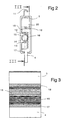
- Figure 2 is a profile view of the load bar of the flap shown in Figure 1, that is to say a view in the direction of arrow A.
- Figure 3 shows a section the length of the load bar according to a section view according to III-III of Figure 2.
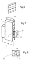
- Figure 4 is a perspective view of the part of the end of the load bar according to a first variant.
- Figure 5 is a sectional view along V-V of the figure 4.
- Figure 6 shows, in perspective, a section of a rack mounted in the slide in which slides the end of the load bar shown in Figures 4 and 5.
- FIG. 8 illustrates the operation of this second variant.
- Figure 1 shows schematically a rolling shutter formed of an apron 1 made up of articulated blades 2 to each other and ended with a load bar 3 fitted with a safety edge 4 retractable into the load bar 3, blades 2, load bar 3 and its feeler bar 4 being guided by their ends, in two opposite slides 5 and 6 extending vertically on either side of a doorway, for example a window doorway represented here by its tablet 7.
- the apron 1 is wound on a winding tube 8 driven by a motor 9 which is associated with electronic control 10 driving the engine.
- the load bar 3 has a tubular profile of general shape rectangular. It is provided, on its upper side, a hook 11 for its attachment to the last blade 2 of the roller shutter deck. Approximately halfway up, the load bar 3 internally two longitudinal ribs 12 and 13 defining between they a semi-cylindrical housing 14 in which is mounted a pinion 15 extending over the entire length of the load bar. This pinion 15 meshes with a rack 16 formed on the part of the bar feeler 4 extending into the load bar 3 and can slide vertically in the latter.
- the safety edge 4 present, inside the charge 3, two enlargements 17 and 18, enlargement 17 forming retaining stop for the safety edge in the load bar and the widening 18 being intended to actuate a pusher 19 of a commanding switch a transmitter 20 housed in the upper part of the load bar 3.
- the signal emitted by the transmitter 20 is received by a receiver mounted in the electronics of command 10.
- control electronics 10 During the rolling shutter, if the bar feeler encounters an obstacle, it is pushed back to inside the load bar 3 and actuates the transmitter switch 20 which emits a signal interpreted by the control electronics 10 as a engine stop order 9, control electronics 10 furthermore capable of controlling a rotation in the direction reverse of the motor causing the shutter to rise rolling to release the obstacle, especially when the obstacle consists of part of a human body.
- the load bar 3 and its safety edge 4 have the same appearance on their entire length, which allows them to be cut at the desired length.
- FIG. 4 A first solution is shown in Figures 4, 5 and 6.
- a pallet 21 articulated around a horizontal axis 22 and constituting a retractable stop in the form of a pawl.
- This pallet 21 rests on the upper end of the safety edge 4, so that when the safety edge 4 is in the low position relative to the load bar 3, the lower end of the pallet 21, which passes through the wall of the load bar 3 through a window 23, approximately flush the external lateral face of the load bar.
- the pallet 21 is mounted in an auxiliary part 30 which is fixed to the end of the load bar 3 cut to this effect at a width less than that of the bar feeler. It is thus possible to mount a part 30 at both ends of the load bar, which provides symmetrical load bar retention in both slides when locking and prevents thus a tilting of the load bar.
- one end of the pinion 15 has a threaded portion 26 on which is mounted a nut 27 of rectangular section of width such that it can slide very freely in one of the slides 5 or 6, while being prevented from turning in this slide.
- the orientation of the bar load or the direction of the thread 26 is such that when the safety edge 4 encounters an obstacle and causes the pinion 15 in rotation, the nut 27 moves in direction of the bottom of the slide 5, as illustrated by Figure 8.
- the application of the nut 27 against the bottom slide 5 has the effect of blocking the bar load 3 between slides 5 and 6, this blocking causing the engine to stop as in the case previous.
Landscapes
- Engineering & Computer Science (AREA)
- Structural Engineering (AREA)
- Mechanical Engineering (AREA)
- Architecture (AREA)
- Civil Engineering (AREA)
- Operating, Guiding And Securing Of Roll- Type Closing Members (AREA)
- Preliminary Treatment Of Fibers (AREA)
- Vehicle Body Suspensions (AREA)
- Radiation-Therapy Devices (AREA)
- Toys (AREA)
Claims (4)
- Motorgetriebener Rolladen mit einer Rolljalousie (1), bestehend aus gelenkig miteinander verbundenen Lamellen (2) und einer Laststange (3), welche in zwei Gleitschienen (5,6) geführt sind, wobei die hohle Laststange (3) mit einer in diese einschiebbaren Fühlerstange (4) zum Erfassen eines Hindernisses versehen ist und diese Laststange (3) einen Mechanismus aufweist, der mit der Fühlerstange (4) zusammenwirkt, um eine Erfassung des Hindernisses an allen Punkten dieser Fühlerstange (4) zu gewährleisten, dadurch gekennzeichnet, dass der erwähnte Mechanismus aus einem Ritzel (15) besteht, das sich über wenigstens den grössten Teil der Länge der Laststange (3) erstreckt und auf seiner ganzen Länge mit einer fest an der Fühlerstange (4) angebrachten Zahnstange (16) in Eingriff ist.
- Rolladen nach Anspruch 1, dadurch gekennzeichnet, dass sie einen Sender (20) aufweist, der direkt durch die Fühlerstange (4) beim Auftreffen auf ein Hindernis einschaltbar ist.
- Rolladen nach Anspruch 1, welcher mit Mitteln (10) zum Erfassen des Drehmoment ausgerüstet ist, dadurch gekennzeichnet, dass er wenigstens einen einklappbaren Anschlag (21) aufweist, der direkt durch die Fühlerstange (4) steuerbar ist und mit wenigstens einer festen Verzahnung (25) zusammenwirkt, um die Blockierung der Laststange (3) bei der Abwärtsbewegung zu gewährleisten.
- Rolladen nach Anspruch 1, welcher mit Mitteln (10) zum Erfassen des Drehmoments ausgerüstet ist, dadurch gekennzeichnet, dass das Ritzel (15) ein mit Gewinde versehenes Ende (26) aufweist, welches in eine Schraubenmutter (27) eingreift, die in einer der Gleitschienen gegen Drehung gehalten ist, derart, dass eine Drehung des Ritzels (15) in dem dem Einschieben der Fühlerstange (4) in die Laststange (3) entsprechenden Sinne die Schraubenmutter (27) gegen den Boden der Gleitschiene (5) drückt und die Laststange (3) in den Gleitschienen blockiert.
Applications Claiming Priority (2)
| Application Number | Priority Date | Filing Date | Title |
|---|---|---|---|
| FR9712434A FR2769340B1 (fr) | 1997-10-06 | 1997-10-06 | Volet roulant motorise |
| FR9712434 | 1997-10-06 |
Publications (2)
| Publication Number | Publication Date |
|---|---|
| EP0908593A1 EP0908593A1 (de) | 1999-04-14 |
| EP0908593B1 true EP0908593B1 (de) | 2002-03-27 |
Family
ID=9511873
Family Applications (1)
| Application Number | Title | Priority Date | Filing Date |
|---|---|---|---|
| EP98810959A Expired - Lifetime EP0908593B1 (de) | 1997-10-06 | 1998-09-24 | Motorgetriebene Rolläden |
Country Status (6)
| Country | Link |
|---|---|
| EP (1) | EP0908593B1 (de) |
| JP (1) | JPH11190183A (de) |
| AT (1) | ATE215172T1 (de) |
| DE (1) | DE69804401T2 (de) |
| ES (1) | ES2130110T3 (de) |
| FR (1) | FR2769340B1 (de) |
Families Citing this family (4)
| Publication number | Priority date | Publication date | Assignee | Title |
|---|---|---|---|---|
| FR2819545B1 (fr) * | 2001-01-18 | 2003-08-15 | Bubendorff Volet Roulant | Volet roulant pourvu d'un dispositif de detection d'obstacle |
| GB0602383D0 (en) * | 2006-02-07 | 2006-03-15 | Ansa Door Systems Ltd | Improvements in and relating to doors |
| FR2930586A1 (fr) | 2008-04-23 | 2009-10-30 | Zurfluh Feller Soc Par Actions | Volet roulant equipe d'un frein, frein et lame de freinage pour un tel volant. |
| DE102010062673B4 (de) | 2010-12-08 | 2014-02-20 | Hörmann KG Antriebstechnik | Torflügel, Schließeinrichtung sowie Verfahren zum Erkennen einer Blockierung |
Family Cites Families (3)
| Publication number | Priority date | Publication date | Assignee | Title |
|---|---|---|---|---|
| FR2649260B1 (fr) | 1989-06-30 | 1996-05-15 | Somfy | Dispositif d'arret d'un moteur asynchrone monophase a condensateur |
| JPH07331973A (ja) * | 1994-06-14 | 1995-12-19 | Mori Denki Kk | シャッターの障害物感知装置 |
| JP3168332B2 (ja) * | 1995-06-29 | 2001-05-21 | 三和シヤッター工業株式会社 | 建築用電動シャッターにおける障害物検知装置 |
-
1997
- 1997-10-06 FR FR9712434A patent/FR2769340B1/fr not_active Expired - Fee Related
-
1998
- 1998-09-24 AT AT98810959T patent/ATE215172T1/de not_active IP Right Cessation
- 1998-09-24 EP EP98810959A patent/EP0908593B1/de not_active Expired - Lifetime
- 1998-09-24 DE DE69804401T patent/DE69804401T2/de not_active Expired - Lifetime
- 1998-09-24 ES ES98810959T patent/ES2130110T3/es not_active Expired - Lifetime
- 1998-10-05 JP JP10283005A patent/JPH11190183A/ja active Pending
Also Published As
| Publication number | Publication date |
|---|---|
| EP0908593A1 (de) | 1999-04-14 |
| DE69804401T2 (de) | 2002-11-21 |
| ES2130110T1 (es) | 1999-07-01 |
| DE69804401D1 (de) | 2002-05-02 |
| JPH11190183A (ja) | 1999-07-13 |
| FR2769340B1 (fr) | 1999-12-03 |
| ES2130110T3 (es) | 2002-11-16 |
| FR2769340A1 (fr) | 1999-04-09 |
| ATE215172T1 (de) | 2002-04-15 |
Similar Documents
| Publication | Publication Date | Title |
|---|---|---|
| EP0272733A1 (de) | Rolltorvorrichtung | |
| FR2588307A1 (fr) | Dispositif d'ecran motorise | |
| FR2987393A1 (fr) | Dispositif de verrouillage et de deverrouillage automatique du tablier d'un rideau, d'un volet roulant ou d'une porte sectionnelle | |
| EP0908593B1 (de) | Motorgetriebene Rolläden | |
| FR2859716A1 (fr) | Dispositif et procede pour recouvrir et decouvrir une surface par un element de couverture enroulable | |
| FR2474971A1 (fr) | Dispositif de manoeuvre d'un toit ouvrant de vehicule automobile | |
| EP1730379A1 (de) | Schnellfalttür | |
| FR2614929A1 (fr) | Tablier pour volet roulant | |
| FR3005326A1 (fr) | Dispositif motorise de verrouillage/deverrouillage d'un ouvrant, notamment d'une fenetre | |
| FR2890335A1 (fr) | Dispositif formant pare-soleil pour un pare-brise d'un vehicule automobile occupant une partie du pavillon du vehicule | |
| EP3936383B1 (de) | Modulierbares deckenbett für ausgestatteten kastenwagen | |
| EP0426537A1 (de) | Tür mit aufrollbarem Vorhang | |
| FR2703720A1 (fr) | Dispositif de verrouillage automatique d'une porte, en particulier d'une porte basculante. | |
| EP0889194A1 (de) | Rolladen | |
| EP1524399A1 (de) | Schutzgitter | |
| EP2017105B1 (de) | Abdeckungsrollo für Kraftfahrzeug mit Schwenkzugstange und entsprechendes Fahrzeug | |
| FR2644507A1 (fr) | Installation comprenant au moins un vantail pivotant autour d'un axe vertical | |
| EP0352206A1 (de) | nager für Kipp- oder Schwingdachfenster | |
| FR2520432A1 (fr) | Dispositif de verrouillage automatique du tablier deploye d'un volet roulant | |
| FR2536489A1 (fr) | Dispositif permettant de deplacer en translation un element coulissant | |
| EP1336519B1 (de) | Fensterrolle für Kraftfahrzeug mit Zugstange mit mobiler Abdeckung | |
| EP3851628A1 (de) | Ausfachungsanordnung mit einem rollladenkasten und fensterrahmen, der diese ausfachungsanordnung umfasst | |
| EP0875656B1 (de) | Aufrollbares motorisiertes Produkt, welches mit einer Stopvorrichtung ausgerüstet ist, die eine Gewichtsveränderung erfasst | |
| FR2721972A1 (fr) | Dispositif de blocage pour volet roulant | |
| FR2990711A3 (fr) | Auvent a tissu de couverture retractable |
Legal Events
| Date | Code | Title | Description |
|---|---|---|---|
| PUAI | Public reference made under article 153(3) epc to a published international application that has entered the european phase |
Free format text: ORIGINAL CODE: 0009012 |
|
| AK | Designated contracting states |
Kind code of ref document: A1 Designated state(s): AT BE CH DE ES GB IT LI NL SE |
|
| AX | Request for extension of the european patent |
Free format text: AL;LT;LV;MK;RO;SI |
|
| REG | Reference to a national code |
Ref country code: ES Ref legal event code: BA2A Ref document number: 2130110 Country of ref document: ES Kind code of ref document: T1 |
|
| 17P | Request for examination filed |
Effective date: 19990922 |
|
| AKX | Designation fees paid |
Free format text: AT BE CH DE ES GB IT LI NL SE |
|
| GRAG | Despatch of communication of intention to grant |
Free format text: ORIGINAL CODE: EPIDOS AGRA |
|
| 17Q | First examination report despatched |
Effective date: 20010615 |
|
| RAP1 | Party data changed (applicant data changed or rights of an application transferred) |
Owner name: SOMFY |
|
| GRAG | Despatch of communication of intention to grant |
Free format text: ORIGINAL CODE: EPIDOS AGRA |
|
| GRAH | Despatch of communication of intention to grant a patent |
Free format text: ORIGINAL CODE: EPIDOS IGRA |
|
| GRAH | Despatch of communication of intention to grant a patent |
Free format text: ORIGINAL CODE: EPIDOS IGRA |
|
| REG | Reference to a national code |
Ref country code: GB Ref legal event code: IF02 |
|
| GRAA | (expected) grant |
Free format text: ORIGINAL CODE: 0009210 |
|
| AK | Designated contracting states |
Kind code of ref document: B1 Designated state(s): AT BE CH DE ES GB IT LI NL SE |
|
| PG25 | Lapsed in a contracting state [announced via postgrant information from national office to epo] |
Ref country code: NL Free format text: LAPSE BECAUSE OF FAILURE TO SUBMIT A TRANSLATION OF THE DESCRIPTION OR TO PAY THE FEE WITHIN THE PRESCRIBED TIME-LIMIT Effective date: 20020327 Ref country code: GB Free format text: LAPSE BECAUSE OF FAILURE TO SUBMIT A TRANSLATION OF THE DESCRIPTION OR TO PAY THE FEE WITHIN THE PRESCRIBED TIME-LIMIT Effective date: 20020327 Ref country code: AT Free format text: LAPSE BECAUSE OF FAILURE TO SUBMIT A TRANSLATION OF THE DESCRIPTION OR TO PAY THE FEE WITHIN THE PRESCRIBED TIME-LIMIT Effective date: 20020327 |
|
| REF | Corresponds to: |
Ref document number: 215172 Country of ref document: AT Date of ref document: 20020415 Kind code of ref document: T |
|
| REG | Reference to a national code |
Ref country code: CH Ref legal event code: EP |
|
| REF | Corresponds to: |
Ref document number: 69804401 Country of ref document: DE Date of ref document: 20020502 |
|
| REG | Reference to a national code |
Ref country code: CH Ref legal event code: NV Representative=s name: BUGNION S.A. |
|
| PG25 | Lapsed in a contracting state [announced via postgrant information from national office to epo] |
Ref country code: SE Free format text: LAPSE BECAUSE OF FAILURE TO SUBMIT A TRANSLATION OF THE DESCRIPTION OR TO PAY THE FEE WITHIN THE PRESCRIBED TIME-LIMIT Effective date: 20020627 |
|
| NLV1 | Nl: lapsed or annulled due to failure to fulfill the requirements of art. 29p and 29m of the patents act | ||
| GBV | Gb: ep patent (uk) treated as always having been void in accordance with gb section 77(7)/1977 [no translation filed] |
Effective date: 20020327 |
|
| REG | Reference to a national code |
Ref country code: ES Ref legal event code: FG2A Ref document number: 2130110 Country of ref document: ES Kind code of ref document: T3 |
|
| PLBE | No opposition filed within time limit |
Free format text: ORIGINAL CODE: 0009261 |
|
| STAA | Information on the status of an ep patent application or granted ep patent |
Free format text: STATUS: NO OPPOSITION FILED WITHIN TIME LIMIT |
|
| 26N | No opposition filed |
Effective date: 20021230 |
|
| PGFP | Annual fee paid to national office [announced via postgrant information from national office to epo] |
Ref country code: ES Payment date: 20090929 Year of fee payment: 12 |
|
| PGFP | Annual fee paid to national office [announced via postgrant information from national office to epo] |
Ref country code: DE Payment date: 20090928 Year of fee payment: 12 Ref country code: CH Payment date: 20091012 Year of fee payment: 12 |
|
| PGFP | Annual fee paid to national office [announced via postgrant information from national office to epo] |
Ref country code: IT Payment date: 20090919 Year of fee payment: 12 |
|
| PGFP | Annual fee paid to national office [announced via postgrant information from national office to epo] |
Ref country code: BE Payment date: 20091020 Year of fee payment: 12 |
|
| BERE | Be: lapsed |
Owner name: *SOMFY Effective date: 20100930 |
|
| REG | Reference to a national code |
Ref country code: CH Ref legal event code: PL |
|
| PG25 | Lapsed in a contracting state [announced via postgrant information from national office to epo] |
Ref country code: IT Free format text: LAPSE BECAUSE OF NON-PAYMENT OF DUE FEES Effective date: 20100924 |
|
| REG | Reference to a national code |
Ref country code: DE Ref legal event code: R119 Ref document number: 69804401 Country of ref document: DE Effective date: 20110401 |
|
| PG25 | Lapsed in a contracting state [announced via postgrant information from national office to epo] |
Ref country code: CH Free format text: LAPSE BECAUSE OF NON-PAYMENT OF DUE FEES Effective date: 20100930 Ref country code: DE Free format text: LAPSE BECAUSE OF NON-PAYMENT OF DUE FEES Effective date: 20110401 Ref country code: BE Free format text: LAPSE BECAUSE OF NON-PAYMENT OF DUE FEES Effective date: 20100930 Ref country code: LI Free format text: LAPSE BECAUSE OF NON-PAYMENT OF DUE FEES Effective date: 20100930 |
|
| REG | Reference to a national code |
Ref country code: ES Ref legal event code: FD2A Effective date: 20111019 |
|
| PG25 | Lapsed in a contracting state [announced via postgrant information from national office to epo] |
Ref country code: ES Free format text: LAPSE BECAUSE OF NON-PAYMENT OF DUE FEES Effective date: 20100925 |