EP0871097B1 - Programmierbare steuerung - Google Patents
Programmierbare steuerung Download PDFInfo
- Publication number
- EP0871097B1 EP0871097B1 EP96942646A EP96942646A EP0871097B1 EP 0871097 B1 EP0871097 B1 EP 0871097B1 EP 96942646 A EP96942646 A EP 96942646A EP 96942646 A EP96942646 A EP 96942646A EP 0871097 B1 EP0871097 B1 EP 0871097B1
- Authority
- EP
- European Patent Office
- Prior art keywords
- program
- interlock
- control program
- control
- memory
- Prior art date
- Legal status (The legal status is an assumption and is not a legal conclusion. Google has not performed a legal analysis and makes no representation as to the accuracy of the status listed.)
- Expired - Lifetime
Links
Images


Classifications
-
- G—PHYSICS
- G05—CONTROLLING; REGULATING
- G05B—CONTROL OR REGULATING SYSTEMS IN GENERAL; FUNCTIONAL ELEMENTS OF SUCH SYSTEMS; MONITORING OR TESTING ARRANGEMENTS FOR SUCH SYSTEMS OR ELEMENTS
- G05B19/00—Program-control systems
- G05B19/02—Program-control systems electric
- G05B19/04—Program control other than numerical control, i.e. in sequence controllers or logic controllers
- G05B19/05—Programmable logic controllers, e.g. simulating logic interconnections of signals according to ladder diagrams or function charts
- G05B19/056—Programming the PLC
-
- G—PHYSICS
- G05—CONTROLLING; REGULATING
- G05B—CONTROL OR REGULATING SYSTEMS IN GENERAL; FUNCTIONAL ELEMENTS OF SUCH SYSTEMS; MONITORING OR TESTING ARRANGEMENTS FOR SUCH SYSTEMS OR ELEMENTS
- G05B2219/00—Program-control systems
- G05B2219/10—Plc systems
- G05B2219/13—Plc programming
- G05B2219/13075—User program, then interlock program to override certain conditions
-
- G—PHYSICS
- G05—CONTROLLING; REGULATING
- G05B—CONTROL OR REGULATING SYSTEMS IN GENERAL; FUNCTIONAL ELEMENTS OF SUCH SYSTEMS; MONITORING OR TESTING ARRANGEMENTS FOR SUCH SYSTEMS OR ELEMENTS
- G05B2219/00—Program-control systems
- G05B2219/10—Plc systems
- G05B2219/13—Plc programming
- G05B2219/13077—Interlock conditions stored in tables
-
- G—PHYSICS
- G05—CONTROLLING; REGULATING
- G05B—CONTROL OR REGULATING SYSTEMS IN GENERAL; FUNCTIONAL ELEMENTS OF SUCH SYSTEMS; MONITORING OR TESTING ARRANGEMENTS FOR SUCH SYSTEMS OR ELEMENTS
- G05B2219/00—Program-control systems
- G05B2219/10—Plc systems
- G05B2219/13—Plc programming
- G05B2219/13078—Sequence operation and interlock set programs are separated
Definitions
- the present invention relates to a programmable controller.
- a user program for controlling a controlled system is contained in a programmable controller.
- the user program is generally described by a ladder language, an SFC (a sequential function chart), and so forth.
- the user program is constituted by a plurality of modules in many cases.
- the modules are respectively allocated parts of the control of the controlled system. Division of the user program into the plurality of modules is particularly effective in a case where the control of the controlled system is complicated. It is also effective in order to facilitate the creation of the user program or share the creation of the user program among a plurality of persons even if a control system is not necessarily complicated.
- the control system is divided depending on control equipments constituting the controlled system, the types of driving devices, the control functions and so forth, and the control of each of parts formed by the division is allocated to each of the modules.
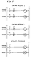
- Fig. 7 illustrates one example of a control system using a programmable controller.
- a conveyer for carrying an article from a point x1 to a point x2.
- a motor M2 is provided for driving the conveyer in the forward direction (rightward in Fig. 7 ).
- a conveyer for carrying the article from the point x2 to a point x3 is driven in the forward direction by a motor M3. It is necessary to return the article from the point x3 (or x2) to the point x2 (or x1) in an emergency, or in order to cope with the other situation.
- a motor M1 is provided in order to drive the above-mentioned two conveyers in the reverse direction (leftward in Fig. 7 ).
- a plurality of user program modules share the control of the control system depending on the share of driving devices (control equipments), the control ranges, the driving directions and so forth.
- control range is divided into right and left control ranges with the point x2 used as the boundary, and user program modules sharing each of the control ranges are created.
- a switch SW2 for moving the conveyer in the forward direction and a switch SW1 for moving the conveyer in the reverse direction are provided in a control panel 51.
- a switch SW4 for moving the conveyer in the forward direction and a switch SW3 for moving the conveyer in the reverse direction are provided in a control panel 52.
- Switch inputs from the switches SW1 to SW4 are fed to an I/O unit 41 connected to a programmable controller 40.
- the motors M1 to M3 are driven by output signals from the I/O unit 41.
- a user program for controlling the motors M1 to M3 in response to the inputs from the switches SW1 to SW4 is stored in a user program memory in the programmable controller 40.
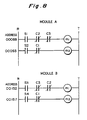
- a user program module A for controlling the left half range and a user program module B for controlling the right half range are illustrated by a ladder diagram in Fig. 8 .
- reference signs m1, m2 and m3 denote relays for respectively representing outputs for driving the motors M1, M2 and M3.
- Reference signs s1, s2, s3 and s4 denote input contacts (normally open contacts) respectively representing signals fed from the switches SW1, SW2, SW3 and SW4.
- Reference signs c1, c2 and c3 denote internal contacts (normally closed contacts) respectively opened or closed by the relays m1, m2 and m3.
- the input contact s2 when the switch SW2 is turned on, the input contact s2 is closed, whereby the relay m2 operates so that the motor M2 is driven, provided that the internal contact c1 is on (provided that the motor M1 is not driven) (an address 00093).
- the switch SW1 when the switch SW1 is turned on, the input contact s1 is closed, whereby the relay m1 operates so that the motor M1 is driven, provided that the internal contacts c2 and c3 are on (provided that both the motors M2 and M3 are not driven) (an address 00088).
- the input contact s4 when the switch SW4 is turned on, the input contact s4 is closed, whereby the relay m3 operates so that the motor M3 is driven, provided that the internal contact c1 is on (provided that the motor M1 is not driven) (an address 00157).
- the switch SW3 is turned on, the input contact s3 is closed, whereby the relay m1 operates so that the motor M1 is driven, provided that the internal contacts c2 and c3 are on (provided that both the motors M2 and M3 are not driven) (an address 00152).
- interlock program To prevent an equipment or a device from starting its operations or prevent the operations from being continued unless conditions set in advance are satisfied is referred to as interlock.
- the internal contacts c1, c2 and c3 realize the interlock.
- a program for realizing the interlock (including its part) is referred to as an interlock program.
- inputs are s1 and s2, and outputs are m1 and m2.
- the internal contacts c1 and c2 are respectively related to the outputs m1 and m2.
- the internal contact c3 is related to the output m3 of the module B.
- the internal contact c2 is related to the output m2 of the module A.
- the interlock program in each of the user program modules include an element related to the module and an element related to the other module in many cases.
- the description of the element related to the other user program module particularly involves difficulties in many cases. The reason for this is that when the one module is created, the input and output states, the order in which programs are executed and so forth in the other module must be sufficiently grasped.
- a plurality of persons share the creation of the modules, it involves further difficulties.
- JP 07 199801 A and parallel US 5,774,355 A disclose a programmable controller system.
- the system comprises a programmable controller performing the operation sequence control program and an I/O control unit which is physically and logically separated of the controller and performs the interlock control after receiving the data from the programmable controller.
- the programmable controller outputs the commands to the I/O control unit, then the I/O control unit confirms the interlock state of actuators, and afterwards a confirmation is sent from the I/O control unit to the programmable controller.
- An object of the present invention is to provide the structure of a user program, including a part related to interlock, which is relatively easy to create, as well as a programmable controller storing a user program which is relatively easy to create and a method of operating the same.
- a user program for a programmable controller includes a control program from which a description defining interlock conditions is excluded and an interlock program defining interlock conditions for the result of processing conforming to the control program and described separately from the control program, and has a structure ensuring that the interlock program is executed after the control program is executed.
- the user program is stored in a memory device of a programming device (a semiconductor memory, a hard disk, a floppy disk, etc.), a portable recording medium (a CD-ROM, a floppy disk, etc.), a user program memory of the programmable controller, or the like.
- a programming device a semiconductor memory, a hard disk, a floppy disk, etc.
- a portable recording medium a CD-ROM, a floppy disk, etc.
- a user program memory of the programmable controller or the like.
- Such ensuring that the interlock program is executed after the control program is executed can be realized by various methods.
- an address having a small value may be assigned to the control program, and an address having a large value may be assigned to the interlock program.
- An identification code for discriminating between the control program and the interlock program may be assigned.
- the interlock conditions generally mean interlock conditions of an output.
- the present invention is particularly advantageous to a user program having a structure in which a plurality of control program modules are created, thereby sharing control of a controlled system.
- a user program includes a control program, from which a description defining interlock conditions is excluded, comprising a plurality of control program modules sharing control of a controlled system and an interlock program defining interlock conditions for the result of processing conforming to the plurality of control program modules and described separately from the control program, and has a structure ensuring that the interlock program is executed after all the control program modules are executed.
- the interlock conditions of an output in one of the control program modules are determined in relation to an element of control (for example, an output) allocated to the other control program module, and the interlock conditions are described as an interlock program.
- control program modules when one of the control program modules is created, the element related to the other control program module need not be considered, and the order of execution need not be necessarily considered, so that the control program module is easy to create. Even in creating the interlock program, only interlock conditions over the plurality of control program modules may be considered, resulting in improved work efficiency.
- the present invention also provides a method of executing the user program having the above-mentioned structure.
- This method is a method comprising the steps of first, in accordance with the ensuring, reading out the control program from the storage medium, performing processing conforming to the control program and writing the result thereof into an I/O memory, and reading out an interlock program from the storage medium, performing processing conforming to the interlock program and writing the result thereof into the I/O memory after performing the whole of the control program.
- the result of the processing conforming to the interlock program is written into the I/O memory after the result of the processing conforming to the control program is written.
- the result of the processing conforming to the control program and the result of the processing conforming to the interlock program are related to the same output, therefore, priority is given to the result of the processing conforming to the interlock program.
- the interlock conditions which have been incorporated into the interlock program thus correctly function.
- the present invention further provides a programmable controller in which the user program having the above-mentioned structure is set.
- the programmable controller comprises a user program memory storing a user program including a control program from which a description defining interlock conditions is excluded and an interlock program defining interlock conditions for the result of processing conforming to the control program and described separately from the control program, an I/O memory storing data relating to an input for the user program and an output obtained by processing conforming to the user program, and a processor for first reading out the control program from the user program memory, performing processing conforming to the control program and writing the result thereof into the I/O memory, and then reading out the interlock program from the user program memory, performing processing conforming to the interlock program and writing the result thereof into the I/O memory.
- the interlock conditions which have been defined by the interlock program correctly function.
- control program comprises a plurality of control program modules sharing the control of a controlled system
- interlock program describes interlock conditions excluded from the plurality of control program modules.
- the interlock conditions concerning one of the control program modules may be determined in relation to an output generated from the other control program module and described in the interlock program.
- the present invention further provides a device for creating the user program having the above-mentioned structure.
- the programming device comprises an input device and a storage device, and accepts input of a control program from which a description defining interlock conditions is excluded through the input device, accepts input of an interlock program describing interlock conditions for the result of processing conforming to the control program separately from the input of the control program, and stores in the storage device the control program and the interlock program which have been accepted upon correlating therewith.
- the programming device further comprises a display device, and the control program is displayed on the display device, the correlation between the displayed control program and the interlock program, or the interlock program correlated with the displayed control program are displayed thereon. Consequently, the control program and the interlock program related thereto can be well understood.
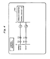
- Fig. 1 illustrates a programming tool and an I/O unit centered around a programmable controller.
- the programmable controller is also referred to as a programmable logic controller (PLC), it is simply described as a programmable controller in this description.
- PLC programmable logic controller
- the programmable controller is not generally connected to a programming tool.
- Fig. 1 illustrates the programmable controller together with devices or equipments around the programmable controller for convenience.
- a programmable controller 10 comprises an MPU (a microprocessing unit) 11, a BPU (a bit processing unit) 12, a system memory (ROM) 13, a work RAM 14, a user program memory (RAM) 15, an I/O memory (RAM) 16 and so forth, which are connected to one another by an internal bus.
- An I/O unit 30 is connected to the BPU 12 by an I/O bus.
- a programming tool 20 is connected to the MPU 11 in the programmable controller 10 through a serial communication line.
- the system memory 13 stores a system program for controlling the overall operation of the programmable controller 10.
- the user program memory 15 stores a user program for controlling the controlled system (the details will be described later) which is created by the programming tool 20.
- the I/O memory 16 stores data representing the states of inputs (input contacts) concerning all input variables used in the user program, data representing the states of outputs (output relays) concerning all output variables obtained by executing the user program, data representing the states of internal contacts required to execute the user program, and the other data.
- the input is obtained from the I/O unit 30, and the output is fed to the I/O unit 30.
- the work RAM 14 is for temporarily storing various types of data in executing the system program and the user program, and is used as a work area.
- the user program generally includes a bit operation instruction and an application operation instruction.
- the BPU 12 reads out the user program from the user program memory 15 in accordance with the system program, hands the application operation instruction to the MPU 11, executes the bit operation instruction, and writes the result of the operation (the state of an output) into the I/O memory 16.
- the BPU 12 transfers, after execution of the whole user program, the result of the operation in the I/O memory 16 to the I/O unit 30, and reads the state of an input signals from the I/O unit 30 and writes the state into the I/O memory 16. Such a refresh operation is performed in a predetermined period.
- the MPU 11 executes the application operation instruction received from the BPU 12, and writes the result of the operation into the I/O memory 16.
- priority is given to the result of the operation later obtained.
- the BPU 12 or the MPU 11 overwrites on the I/O memory 16 the result of the operation on the output (the user program is so created as to correctly function when priority is given to the data later obtained).
- the MPU 11 also communicates with the programming tool 20 through the serial communication line under control of the system program, and transfers the user program created by the programming tool 20 to the user program memory 15 through the BPU 12.
- the I/O unit 30 functions as an input-output interface between the programmable controller 10 and the controlled system, converts signals from sensors arranged in the controlled system, switches of a control panel or the like into input data which can be stored in the I/O memory 16, and generates signals for controlling or driving the control equipments or devices on the basis of output data outputted from the I/O memory 16.
- the programming tool 20 is realized by a so-called personal computer, and comprises a computer 21, an input device (a keyboard, a mouse, etc.) 22 and a display device 23.
- a programming support program recorded on a floppy disk 24 is installed in the computer 21.
- the computer 21 creates the user program in response to an input from the input device 22 in accordance with the programming support program.
- the created user program is transferred to the programmable controller 10, and is stored in the user program memory 15.
- the computer 21 displays the user program which is being created in the process of creating the user program, displays the user program which has been created after the creation, or displays, when the programmable controller 10 executes the user program, a state where the user program is executed.
- Fig. 2 illustrates an example of the user program which has been created in the programming tool 20 and stored in a hard disk of the programming tool 20, or is stored in the user program memory 15.
- the user program is for controlling the control system shown in Fig. 7 as described above, which corresponds to the user program shown in Fig. 8 .
- a control program module a takes charge of the control of the left half range of the control system shown in Fig. 7
- a control program module b takes charge of the control of the right half range thereof.
- An interlock program related to an element (an output variable) in a range other than the range which is taken charge of by the control program module a is excluded from the control program module a .
- an interlock program related to an output variable which is not taken charge of by the control program module b (which is taken charge of by the control program module a ) is not described in the control program module b .
- the interlock programs are together described as an interlock program IP at addresses succeeding addresses assigned to the control program modules a and b .
- the output relay m1 of the motor M1 is turned off.
- the interlock program IP is executed after the control program module a is executed.
- the result of the execution of the operation of the control program module a is written into the I/O memory 16, after which the result of the execution of the interlock program IP is written into (overwritten on) the I/O memory 16.
- the result of the operation on the output relay m1 by a program of the address 00076 assigned to the control program module a is written into the I/O memory 16, and the result of the operation on the output relay m1 by a program of the address 00328 assigned to the interlock program IP is written into the same location of the I/O memory 16, so that priority is always given to the result of the execution of the interlock program IP. Therefore, it is assumed that an indication that the relay m1 should be turned on is stored in the I/O memory 16 in accordance with the program of the address 00076, and that the program of the address 00328 assigned to the interlock program IP is then executed, so that the result of the operation denying that the relay m1 is turned on is obtained.
- control program module b If a switch SW4 is pushed so that an input contact s4 is turned on at an address 00107 assigned to the control program module b , an output relay m3 for driving the motor M3 is turned on, provided that the internal contact c1 is on (provided that the motor M1 is not driven). When the switch SW3 is pushed, an input contact s3 is turned on at an address 00103, so that the output relay m1 for driving the motor M1 is turned on, provided that the internal contact c3 is on (provided that the motor M3 is not driven). Both an input and an output of the control program module b are within the right half range of the control system shown in Fig. 7 .
- the output relay m1 of the motor M1 is turned off.
- the interlock program IP is executed after the control program module b is executed.
- the result of the execution of the operation of the control program module b is written into the I/O memory 16, after which the result of the execution of the interlock program IP is written into (overwritten on) the I/O memory 16.
- a plurality of control program modules and interlock programs related thereto are separately created. Which of the control program module and the interlock program may be first created. In creating the control program module, only input and output variables in a control system whose control is taken charge of by the control program module are considered (an input variable in a control system whose control is taken charge of by the other control program module may be considered). In creating the interlock program, it is examined whether or not each of the input and output variables (or only the output variable) is correlated with two or more control systems whose control is taken charge of by two or more control program modules, and interlock conditions determined by the correlation therebetween are described in consideration of the order.
- All the interlock conditions in the control system whose control is taken charge of by one of the control program modules may be described in the interlock program.
- a combination of the internal contact c2 and the output relay m1 indicates the interlock conditions.
- the program of the address 00076 may be only a combination of the input contact s1 and the output relay m1, and a combination of the internal contact c2 and the output relay m1 may be set as the interlock program.
- control program and the interlock program are correlated with each other by the output variable.
- the control program of the address 00076 includes the output relay m1 concerning the motor M1.
- the interlock program of the address 00328 related thereto also includes the output relay m1 concerning the motor M1. Consequently, the control program of the address 00076 and the interlock program of the address 00328 are correlated with each other by the output relay m1.
- the interlock program of the address 00331 is also related to the output relay m1.
- an operator may enter information relating to the correlation at the time of creating the control program or the interlock program, if required.
- Figs. 3 and 4 illustrate examples of a screen displayed on the display device 23 in the programming tool 20 when the control program module is created (in a case where the interlock program has been already created), after all the programs are completed, or in checking a state where the programmable controller is executed.
- a control program module is displayed, and an interlock condition setting column is displayed beside its output relay.
- a column CM1 indicating that interlock conditions by the internal contact c3 has been set is displayed beside the output relay m1 of the control program module a with respect to the output relay m1.
- a column CM2 indicating that interlock conditions by the internal contact c2 are set is displayed beside the output relay m1 of the control program module b with respect to the output relay m1.
- Such display is performed on the basis of the above-mentioned information relating to the correlation.
- interlock conditions concerning an element included in a control system whose control is taken charge of by the other control program module are not described, interlock conditions are thus displayed in relation to the display of the one control program module, so that it is found that the interlock conditions are set, and it is found what the interlock conditions depend on.
- FIG. 5 illustrates another example of display.
- a control program module a is displayed.
- an interlock program set in relation to the output relay m1 designated by the cursor Cu in the control program module a is displayed in another position on the same screen.
- This display is also achieved by retrieving information relating to the correlation between a control program and an interlock program on a memory. It is thus found that interlock conditions are set in particular output relays of various control programs, and the contents thereof are rapidly found.
- An interlock program must be executed after a control program is executed.
- an interlock program is arranged behind all control programs, as described above. That is, an address assigned to the interlock program shall have a larger value than addresses assigned to all the control programs on the premise that programs are executed in the order of addresses (they are controlled by a system program).
- the addresses may be automatically set by the programming tool 20, or may be manually entered by an operator.
- the other method is a method of automatically or manually adding to an interlock program identification data indicating that it is an interlock program.
- the programmable controller 10 executes the interlock program after executing all the control programs while recognizing the identification data in accordance with a system program.
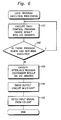
- Fig. 6 shows the procedure for processing conforming to a user program executed in accordance with a system program in the programmable controller 10.
- the user program shall be stored in the user program memory 15.
- Control program modules are successively read out, so that various operations conforming to the programs are executed.
- the result of the operation is written into a corresponding location of the I/O memory 16 (step 101). This processing is repeatedly performed with respect to all the control program modules (step 102).
- Interlock programs are then successively read out, so that various operations conforming to the programs are executed.
- the result of the operation is overwritten on a corresponding location of the I/O memory 16 (step 103).
- the result of the operation of the interlock program precedes the result of the operation of the control program.
- output data in the I/O memory 16 is transferred to the I/O unit 30, and output circuits in the I/O unit 30 are driven on the basis of the output data (step 104).
- Control signals or driving signals are outputted from the I/O unit 30, and are fed to control equipments or devices or driving devices constituting a controlled system.
- Input data generated on the basis of signals fed to the I/O unit 30 from sensors, switches or the like in the controlled system are transferred from the I/O unit 30 to the I/O memory 16, and are written into the I/O memory 16 (step 105).
- the steps 101 to 105 constitute a one-cycle operation in the programmable controller 10, and this operation is repeated in a predetermined period.
Landscapes
- Physics & Mathematics (AREA)
- General Physics & Mathematics (AREA)
- Engineering & Computer Science (AREA)
- Automation & Control Theory (AREA)
- Programmable Controllers (AREA)
Claims (7)
- Programmierbare Steuereinrichtung, die aufweist:einen Benutzerprogramm-Speicher (15) zum Speichern eines Benutzerprogramms, das einschließt ein Steuerprogramm (a, b), von dem eine Beschreibung ausgeschlossen ist, die Interlockbedingungen festlegt, und ein Interlockprogramm (IP), das die Interlockbedingungen für das dem Steuerprogramm entsprechende Ergebnis des Verarbeitens festlegt und die getrennt vom Steuerprogramm beschrieben sind;einen I/O-Speicher (16) zum Speichern von Daten bezüglich einer Eingabe für das Benutzerprogramm und einer Ausgabe, die erhalten wird durch das dem Benutzerprogramm entsprechende Verarbeiten; undeinen Prozessor (11, 12), der geeignet ist zumdadurch gekennzeichnet, dass der Prozessor weiterhin geeignet ist zum Schreiben des Ergebnisses hieraus in den I/O-Speicher (16),
zuerst Auslesen des Steuerprogramms aus dem Benutzerprogramm-Speicher (15), und
Durchführen des Verarbeitens entsprechend des Steuerprogramms;
anschließenden Auslesen des Interlockprogramms (IP) aus dem Benutzerprogramm-Speicher (15),
Durchführen des Verarbeitens entsprechend des Interlockprogramms (IP); und
Schreiben des Ergebnisses hieraus in den I/O-Speicher (16). - Programmierbare Steuereinrichtung nach Anspruch 1, wobei
das Steuerprogramm (a, b) eine Vielzahl von Steuerprogramm-Modulen aufweist, die sich die Steuerung eines gesteuerten Systems teilen, und
das Interlockprogramm (IP) Interlockbedingungen beschreibt, die von der Vielzahl der Steuerprogramm-Module ausgeschlossen sind. - Programmierbare Steuereinrichtung nach Anspruch 2, wobei im Interlockprogramm (IP) das Interlockprogramm, das eines der Steuerprogramm-Module betrifft, Interlockbedingungen beschreibt, die in Bezug auf ein Element der Steuerung bestimmt sind, das dem anderen Steuerprogramm-Modul zugeordnet ist.
- Verfahren zum Ausführen eines Benutzerprogramms bei einer programmierbaren Steuereinrichtung (10),
wobei die Steuereinrichtung (10) ein Speichermedium (15) aufweist zum Speichern eines Benutzerprogramms, das einschließt ein Steuerprogramm (a, b), von dem eine Beschreibung ausgeschlossen ist, die Interlockbedingungen festlegt, und ein Interlockprogramm (IP), das die Interlockbedingungen für das dem Steuerprogramm entsprechende Ergebnis des Verarbeitens festlegt und die getrennt vom Steuerprogramm beschrieben sind;
wobei das Verfahren die Schritte aufweist:zuerst Auslesen des Steuerprogramms (a, b) aus dem Speichermedium (15), undDurchführen des Verarbeitens entsprechend des Steuerprogramms;gekennzeichnet durch
Schreiben des Ergebnisses des Verarbeitens, das dem Steuerprogramm entspricht, in einen I/O-Speicher (16); und danach:Auslesen des Interlockprogramms (IP) aus dem Speichermedium (15);Durchführen des Verarbeitens entsprechend des Interlockprogramms (IP); undSchreiben des Ergebnisses hieraus in den I/O-Speicher (16) nach dem Durchführen des ganzen Steuerprogramms (a, b). - Verfahren nach Anspruch 4, wobei
das Steuerprogramm (a, b) eine Vielzahl von Steuerprogramm-Modulen aufweist, die sich die Steuerung eines gesteuerten Systems teilen, und
das Interlockprogramm (IP) die Interlockbedingungen festlegt für die Ergebnisse des Verarbeitens, die der Vielzahl von Steuerprogramm-Modulen entsprechen und die getrennt von den Steuerprogramm-Modulen beschrieben sind,
wobei das Interlockprogramm nur ausgeführt wird nachdem alle Steuerprogramm-Module ausgeführt sind. - Verfahren nach Anspruch 5, wobei das Interlockprogramm (IP), das sich auf eines der Steuerprogramm-Module bezieht, Interlockbedingungen beschreibt, die in Bezug auf ein Element der Steuerung bestimmt sind, das dem anderen Steuerprogramm-Modul zugeordnet ist.
- Speichermedium zum Speichern eines Steuerprogramms, wobei das Steuerprogramm, wenn es auf einer programmierbaren Steuereinrichtung ausgeführt wird, ein Verfahren nach einem der Ansprüche 4 bis 6 implementiert.
Applications Claiming Priority (3)
| Application Number | Priority Date | Filing Date | Title |
|---|---|---|---|
| JP336939/95 | 1995-12-25 | ||
| JP33693995 | 1995-12-25 | ||
| PCT/JP1996/003790 WO1997023812A1 (en) | 1995-12-25 | 1996-12-25 | Programmable controller |
Publications (3)
| Publication Number | Publication Date |
|---|---|
| EP0871097A1 EP0871097A1 (de) | 1998-10-14 |
| EP0871097A4 EP0871097A4 (de) | 2004-04-14 |
| EP0871097B1 true EP0871097B1 (de) | 2009-06-24 |
Family
ID=18304032
Family Applications (1)
| Application Number | Title | Priority Date | Filing Date |
|---|---|---|---|
| EP96942646A Expired - Lifetime EP0871097B1 (de) | 1995-12-25 | 1996-12-25 | Programmierbare steuerung |
Country Status (5)
| Country | Link |
|---|---|
| US (1) | US6272578B1 (de) |
| EP (1) | EP0871097B1 (de) |
| JP (1) | JP3041959B2 (de) |
| DE (1) | DE69637958D1 (de) |
| WO (1) | WO1997023812A1 (de) |
Families Citing this family (3)
| Publication number | Priority date | Publication date | Assignee | Title |
|---|---|---|---|---|
| DE10028140A1 (de) * | 2000-06-07 | 2001-12-20 | Siemens Ag | Verfahren zur Organisation des Ablaufs elektronisch gesteuerter Schaltvorgänge |
| US9311460B2 (en) * | 2011-03-15 | 2016-04-12 | Omron Corporation | Programmable controller system, tool device, tool program, storage medium, and programmable controller |
| US9921591B2 (en) * | 2012-03-26 | 2018-03-20 | Siemens Schweiz Ag | System and method for HVAC interlocks |
Family Cites Families (8)
| Publication number | Priority date | Publication date | Assignee | Title |
|---|---|---|---|---|
| JPS5899805A (ja) * | 1981-12-09 | 1983-06-14 | Omron Tateisi Electronics Co | プログラマブル・コントロ−ラの図示式モニタ表示方式 |
| JPS60262204A (ja) * | 1984-06-07 | 1985-12-25 | Omron Tateisi Electronics Co | プログラマブル・コントロ−ラ |
| GB2233128B (en) * | 1989-05-01 | 1993-12-01 | Honda Motor Co Ltd | Method of and apparatus for generating control program |
| JP2533370B2 (ja) * | 1989-05-01 | 1996-09-11 | 本田技研工業株式会社 | 制御プログラム作成方法 |
| JP2508872B2 (ja) * | 1990-02-27 | 1996-06-19 | 三菱電機株式会社 | プログラマブルコントロ―ラの制御方法 |
| JPH0643913A (ja) * | 1992-07-23 | 1994-02-18 | Toshiba Corp | ラダー図のインタロック付加装置 |
| JPH0784616A (ja) | 1993-06-30 | 1995-03-31 | Enshu Ltd | シーケンスモニタの自動表示方法 |
| JPH07199801A (ja) * | 1993-12-27 | 1995-08-04 | Canon Inc | プログラマブルコントローラシステム |
-
1996
- 1996-12-25 EP EP96942646A patent/EP0871097B1/de not_active Expired - Lifetime
- 1996-12-25 WO PCT/JP1996/003790 patent/WO1997023812A1/ja not_active Ceased
- 1996-12-25 US US09/091,507 patent/US6272578B1/en not_active Expired - Lifetime
- 1996-12-25 DE DE69637958T patent/DE69637958D1/de not_active Expired - Lifetime
- 1996-12-25 JP JP09523511A patent/JP3041959B2/ja not_active Expired - Lifetime
Also Published As
| Publication number | Publication date |
|---|---|
| DE69637958D1 (de) | 2009-08-06 |
| JP3041959B2 (ja) | 2000-05-15 |
| WO1997023812A1 (en) | 1997-07-03 |
| EP0871097A1 (de) | 1998-10-14 |
| EP0871097A4 (de) | 2004-04-14 |
| US6272578B1 (en) | 2001-08-07 |
Similar Documents
| Publication | Publication Date | Title |
|---|---|---|
| US5404288A (en) | Transfer line control system utilizing distributed computing | |
| EP1815951B1 (de) | Robotersteuerung und robotersystem | |
| US6192331B1 (en) | Method for simulating control functions of a control device | |
| CN113176903B (zh) | Simulink模型应用于不同汽车控制器平台的软件集成方法及系统 | |
| EP0871097B1 (de) | Programmierbare steuerung | |
| US6445973B1 (en) | Personal computer-incorporated numerical control apparatus, and image transfer method for personal computer-incorporated numerical control apparatuses | |
| US5239476A (en) | Multi-level state language controller for multi-threaded machine control | |
| JP7572542B2 (ja) | ロボット制御装置、ロボット制御システム及びロボット制御方法 | |
| EP0092312B1 (de) | Verfahren und Gerät zum Anzeigen von Leiterdiagrammen | |
| EP0649077B1 (de) | Multiple-task Steuerung | |
| JPWO1997023812A1 (ja) | プログラマブル・コントローラ | |
| JPH0217509A (ja) | Cad/cam装置 | |
| JP3365421B2 (ja) | ロボット制御装置 | |
| KR100383896B1 (ko) | 기기 제어 시스템 | |
| EP0089194B1 (de) | Verfahren und Gerät zum Anzeigen von Leiterdiagrammen | |
| JP3334927B2 (ja) | ロボット制御装置 | |
| JPS6319007A (ja) | 数値制御装置におけるデ−タ伝送方法 | |
| JPH0228836A (ja) | 数値制御装置のロード方式 | |
| JPH11134010A (ja) | プログラマブルコントローラにおけるプログラム実行方法 | |
| JP3334971B2 (ja) | ロボット制御装置 | |
| JPS62226309A (ja) | プログラマブルマシンコントロ−ラのromカセツト書込方式 | |
| JPS6121506A (ja) | 作業機械の制御装置 | |
| JPH08328793A (ja) | 機械制御装置 | |
| JPH0772917A (ja) | 数値制御システムのデータアクセス方式 | |
| JPH04177511A (ja) | サーボモータ制御装置 |
Legal Events
| Date | Code | Title | Description |
|---|---|---|---|
| PUAI | Public reference made under article 153(3) epc to a published international application that has entered the european phase |
Free format text: ORIGINAL CODE: 0009012 |
|
| 17P | Request for examination filed |
Effective date: 19980724 |
|
| AK | Designated contracting states |
Kind code of ref document: A1 Designated state(s): DE FR GB IT |
|
| A4 | Supplementary search report drawn up and despatched |
Effective date: 20040302 |
|
| 17Q | First examination report despatched |
Effective date: 20050429 |
|
| 17Q | First examination report despatched |
Effective date: 20050429 |
|
| GRAP | Despatch of communication of intention to grant a patent |
Free format text: ORIGINAL CODE: EPIDOSNIGR1 |
|
| GRAS | Grant fee paid |
Free format text: ORIGINAL CODE: EPIDOSNIGR3 |
|
| GRAA | (expected) grant |
Free format text: ORIGINAL CODE: 0009210 |
|
| AK | Designated contracting states |
Kind code of ref document: B1 Designated state(s): DE FR GB IT |
|
| REG | Reference to a national code |
Ref country code: GB Ref legal event code: FG4D |
|
| REF | Corresponds to: |
Ref document number: 69637958 Country of ref document: DE Date of ref document: 20090806 Kind code of ref document: P |
|
| PLBE | No opposition filed within time limit |
Free format text: ORIGINAL CODE: 0009261 |
|
| STAA | Information on the status of an ep patent application or granted ep patent |
Free format text: STATUS: NO OPPOSITION FILED WITHIN TIME LIMIT |
|
| 26N | No opposition filed |
Effective date: 20100325 |
|
| REG | Reference to a national code |
Ref country code: FR Ref legal event code: PLFP Year of fee payment: 20 |
|
| PGFP | Annual fee paid to national office [announced via postgrant information from national office to epo] |
Ref country code: GB Payment date: 20151223 Year of fee payment: 20 |
|
| PGFP | Annual fee paid to national office [announced via postgrant information from national office to epo] |
Ref country code: FR Payment date: 20151110 Year of fee payment: 20 |
|
| PGFP | Annual fee paid to national office [announced via postgrant information from national office to epo] |
Ref country code: IT Payment date: 20151221 Year of fee payment: 20 Ref country code: DE Payment date: 20151222 Year of fee payment: 20 |
|
| REG | Reference to a national code |
Ref country code: DE Ref legal event code: R071 Ref document number: 69637958 Country of ref document: DE |
|
| REG | Reference to a national code |
Ref country code: GB Ref legal event code: PE20 Expiry date: 20161224 |
|
| PG25 | Lapsed in a contracting state [announced via postgrant information from national office to epo] |
Ref country code: GB Free format text: LAPSE BECAUSE OF EXPIRATION OF PROTECTION Effective date: 20161224 |