EP0870951A2 - Dispositif de commande du rapport pour une transmission à variation de vitesse continue - Google Patents
Dispositif de commande du rapport pour une transmission à variation de vitesse continue Download PDFInfo
- Publication number
- EP0870951A2 EP0870951A2 EP98106350A EP98106350A EP0870951A2 EP 0870951 A2 EP0870951 A2 EP 0870951A2 EP 98106350 A EP98106350 A EP 98106350A EP 98106350 A EP98106350 A EP 98106350A EP 0870951 A2 EP0870951 A2 EP 0870951A2
- Authority
- EP
- European Patent Office
- Prior art keywords
- speed change
- change ratio
- value
- vehicle
- command value
- Prior art date
- Legal status (The legal status is an assumption and is not a legal conclusion. Google has not performed a legal analysis and makes no representation as to the accuracy of the status listed.)
- Granted
Links
Images


Classifications
-
- F—MECHANICAL ENGINEERING; LIGHTING; HEATING; WEAPONS; BLASTING
- F16—ENGINEERING ELEMENTS AND UNITS; GENERAL MEASURES FOR PRODUCING AND MAINTAINING EFFECTIVE FUNCTIONING OF MACHINES OR INSTALLATIONS; THERMAL INSULATION IN GENERAL
- F16H—GEARING
- F16H61/00—Control functions within control units of change-speed- or reversing-gearings for conveying rotary motion ; Control of exclusively fluid gearing, friction gearing, gearings with endless flexible members or other particular types of gearing
- F16H61/66—Control functions within control units of change-speed- or reversing-gearings for conveying rotary motion ; Control of exclusively fluid gearing, friction gearing, gearings with endless flexible members or other particular types of gearing specially adapted for continuously variable gearings
- F16H61/662—Control functions within control units of change-speed- or reversing-gearings for conveying rotary motion ; Control of exclusively fluid gearing, friction gearing, gearings with endless flexible members or other particular types of gearing specially adapted for continuously variable gearings with endless flexible members
- F16H61/66254—Control functions within control units of change-speed- or reversing-gearings for conveying rotary motion ; Control of exclusively fluid gearing, friction gearing, gearings with endless flexible members or other particular types of gearing specially adapted for continuously variable gearings with endless flexible members controlling of shifting being influenced by a signal derived from the engine and the main coupling
- F16H61/66259—Control functions within control units of change-speed- or reversing-gearings for conveying rotary motion ; Control of exclusively fluid gearing, friction gearing, gearings with endless flexible members or other particular types of gearing specially adapted for continuously variable gearings with endless flexible members controlling of shifting being influenced by a signal derived from the engine and the main coupling using electrical or electronical sensing or control means
Definitions
- This invention relates to speed change ratio control of a continuously variable transmission.
- a continuously variable transmission for a vehicle is provided for example with a hydraulic transmission such as a torque-converter or a fluid coupling which transmits the engine rotation power, and a continuously variable transmission (referred to hereafter as CVT) which varies the rotation speed of the hydraulic transmission and transmits it to a vehicle drive shaft.
- a hydraulic transmission such as a torque-converter or a fluid coupling which transmits the engine rotation power
- CVT continuously variable transmission
- Oil pressure acts on each of these pulleys via a speed change control valve, and the width of the pulley is varied according to the oil pressure.
- the speed change ratio is varied by controlling the speed change control valve.
- This oil pressure is supplied to the speed change control valve via a line pressure control valve from an oil pump driven by the engine.
- the speed change control valve comprises a spool valve connected to a step motor via a link. When the link displaces the spool according to an angular position of the step motor, the oil pressure acting on the pulley varies.
- the speed change control valve for example simply transmits pressure from the oil pump to the driven pulley, only the oil pressure acting on the drive pulley being controlled according to a speed change ratio command signal.
- the pressure acting on the drive pulley is 0, the contact radius between the drive pulley and belt is a minimum and the speed change ratio is a maximum.
- the oil pressure acting on the drive pulley is controlled to increase together with the rise of engine rotation speed, and the speed change ratio gradually decreases.
- the step motor varies its angular position according to a speed change ratio command signal output from the control unit, and the spool of the speed change control valve is displaced via the link.
- the control unit calculates a target speed change ratio so that the engine rotation speed corresponds to a depression of an accelerator pedal, and outputs a corresponding speed change ratio command signal to the speed change control valve.
- the displacement of this link is limited by a stopper at its maximum displacement position which corresponds to the valve position at which the valve releases the whole pressure acting on the drive pulley to a drain.
- the starting point for the angular position change of the step motor is set so that it overshoots an angular position at which the link comes in contact with the stopper, or an angular position at which the oil pressure acting on the drive pulley is completely opened to the drain, by a plurality of steps in the direction of increasing speed change ratio.
- the step motor is held in this starting point position. The reason for performing this setting is that, if oil pressure were to act continuously on the drive pulley in the rest state, there would be an undesirable effect on the durability of the CVT.
- the step number of the step motor required for initialization is not necessarily the same for all transmission systems of the same specification.
- the response delay of the transmission increases during the accelerating process of the vehicle when it is started. This response delay adversely affects the acceleration performance of the vehicle.
- the angular position of the step motor has overshot the control start position, the vehicle starts with a speed change ratio which is smaller than the command value. Such a smaller speed change ratio also affects the acceleration performance of the vehicle.
- the above initialization errors may also cause the real speed change ratio to overshoot the target speed change ratio during the acceleration after the vehicle is started.
- this invention provides a speed change ratio controller for such a continuously variable transmission which continuously vary a rotation speed of an engine of a vehicle via an actuator and transmits a varied rotation to a vehicle drive shaft.
- the controller comprises a sensor for detecting a running state of the vehicle, a sensor for detecting a real speed change ratio of the transmission, a sensor for detecting a vehicle speed, and a microprocessor.
- the microprocessor is programmed to set a target speed change ratio from the running state, set a temporary target speed change ratio smaller than a largest speed change ratio of the transmission, compute a dynamic characteristic estimated value of the continuously variable transmission for each speed change ratio, calculate a speed change ratio output value based on the dynamic characteristic estimated value and the lesser of the target speed change ratio and the temporary target speed change ratio when the vehicle speed is equal to or greater than a predetermined speed, compute an external disturbance compensating value under a predetermined time constant based on a speed change ratio command value, the real speed change ratio and the dynamic characteristic estimated value, calculate the speed change ratio command value based on the speed change ratio output value and the external disturbance compensating value, compute an operating command value of the actuator according to the speed change ratio command value, and control the actuator based on the operating command value,
- the microprocessor is further programmed to set the target speed change ratio to the largest speed change ratio when the operating command value is less than a predetermined first reference value, and set the temporary target speed change ratio so that the temporary target speed change ratio gradually decreases as the operating command value increases when the operating command value is equal to or larger than the predetermined first reference value.
- microprocessor is further programmed to set the temporary target speed change ratio to be equal to the largest speed change ratio when the vehicle speed is lower than the predetermined speed.
- microprocessor is further programmed to set the temporary target speed change ratio to gradually decrease from the largest speed change ratio as the operating command value increases, when the vehicle speed is equal to or greater than the predetermined speed.
- the microprocessor is further programmed to set temporary target speed change ratio to be equal to the target speed change ratio when the operating command value is equal to or greater than a predetermined second reference value which is larger than the first predetermined reference value.
- microprocessor is further programmed to compute a different operating command value when the speed change ratio is increasing and when the speed change ratio is decreasing.
- the microprocessor is programmed to set a target speed change ratio from the running state, compute a dynamic characteristic estimated value of the continuously variable transmission for each speed change ratio, calculate a speed change ratio output value based on the dynamic characteristic estimated value so that the real speed change ratio follows the target speed change ratio, determine whether or not the vehicle speed is within a predetermined speed range, set a time constant which has a larger value when the vehicle speed is within the predetermined speed range than when the vehicle speed is out of the predetermined speed range, compute an external disturbance compensating value under the time constant based on a speed change ratio command value, the real speed change ratio and the dynamic characteristic estimated value, calculate the speed change ratio command value based on the speed change ratio output value and the external disturbance compensating value, compute an operating command value of the actuator according to the speed change ratio command value, and control the actuator based on the operating command value.
- the predetermined speed range is set from 5km/hr to 10 km/hr.
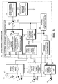
- Fig. 1 is a schematic diagram of a continuously variable transmission and a speed change ratio controller according to this invention.
- Fig. 2 is a schematic diagram of an oil pressure control unit according to this invention.
- Fig. 3 is a block diagram of an electronic control unit according to this invention.
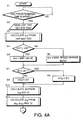
- Figs. 4A and 4B are flowcharts for describing a speed change control process performed by the electronic control unit.
- Fig. 5 is a diagram showing the contents of a map of a time constant Tp of a CVT stored in the electronic control unit.
- Fig. 6 is a diagram showing a relation between a speed change ratio and step motor angular position ⁇ .
- Fig. 7 is an enlarged view of an essential part in Fig. 6.
- Fig. 8 is a diagram showing the contents of a map of step motor angular position ⁇ stored by the electronic control unit.
- Fig. 9 is a timing chart showing a change of target speed change ratio ip , real speed change ratio ip R , target engine rotation speed, real engine rotation speed Ne , vehicle speed VSP and acceleration G according to the speed change ratio controller.
- a continuously variable transmission (CVT) 17 is connected to an engine, not illustrated, via a torque converter 12 comprising a lock up clutch 11.
- the CVT 17 comprises a drive pulley 16 which is connected to a torque-converter 12, and a driven pulley 26 which is connected to an output shaft 33.
- a V-belt 24 is looped around these pulleys 16 and 26.
- the drive pulley 16 comprises a fixed conical plate 18 which rotates together with the torque-converter 12 and a movable conical plate 22 facing the fixed conical plate 18, a V-shaped pulley groove being formed between these conical plates 18 and 22.
- the movable conical plate 22 is displaced according to an oil pressure supplied to a drive pulley cylinder chamber 20, i.e. the drive pulley oil pressure, in the direction of the pulley shaft.
- the driven pulley 26 comprises the fixed conical plate 30 which rotates together with a pulley shaft 33, and a movable conical plate 34 arranged facing the fixed conical plate 30, a V-shaped pulley groove being formed between these conical plates 30 and 34.
- the movable conical plate 34 is displaced according to a line pressure supplied to a driven pulley cylinder chamber 32, i.e. according to a driven pulley pressure, in the direction of the pulley shaft.
- the movable conical plate 34 has a larger pressure-receiving area than the movable conical plate 22.
- a drive torque input from an engine is input to the drive pulley 16 of the CVT 17 via the torque-converter 12, and is transmitted to the driven pulley 26 via the V-belt 24 from the drive pulley 16.
- the width of the V-shaped groove of the drive pulley 16 is reduced, the contact radius between the drive pulley 16 and V-belt 24 becomes large, and the rotation speed of the output shaft increases. Conversely, if the width of the V-shaped groove of the drive pulley 16 is increased, the contact radius between the drive pulley 16 and V-belt 24 becomes small, and the rotation speed of the output shaft drops.
- the speed change ratio of the CVT 17 and a contact frictional force between the V-belt 24 and conical plates are controlled by an oil pressure control unit 3.
- the oil pressure control unit 3 as shown in Fig. 2, is provided with a speed control valve 63 of the spool type, a step motor 64 which displaces the spool of the speed control valve 63 according to a target speed change ratio calculated by an electronic control unit 1 and a line pressure control-valve 60 for controlling a line pressure introduced from an oil pump 61.
- the line pressure control valve 60 adjusts line pressure according to a pilot pressure supplied from a spool valve 77 in response to a negative pressure diaphragm 76 which detects an intake negative pressure of the engine.
- the line pressure adjusted by the line pressure control valve 60 is supplied to the speed change control valve 63, and line pressure is also supplied to the spool valve 77 as a source of pilot pressure generated by the spool valve 77.
- the pilot pressure of the spool valve 77 is supplied as a forward/reverse clutch tightening pressure of a clutch via a manual valve 78 in response to a shift lever.
- a rotation speed signal from a drive pulley rotation speed sensor 6 which detects a rotation speed Npri of the drive pulley 16 of CVT 17, i.e. the input rotation speed to the CVT 17, and a rotation speed signal Nsec of the driven pulley 26, i.e. a rotation speed signal from a driven pulley rotation speed sensor 7 which detects the output rotation speed of the CVT 17, are input to the electronic control unit 1.
- the rotation speed signal from the driven pulley 26 is also used as a vehicle speed VSP .
- a sensor detecting the accelerator depression amount directly can also be used instead of the throttle opening sensor 5.
- the electronic control unit 1 controls a speed change ratio according to the drive state and the driver's needs.
- the control of speed change ratio is performed by controlling the oil pressure supplied to the drive pulley cylinder chamber 20.
- the speed change ratio varies in the direction in which the output rotation increases, and when this oil pressure drops, the speed change ratio varies in the direction in which the output rotation decreases.
- This control is performed by a signal output to the step motor 64 which drives the speed control valve 63 of the oil pressure control unit 3 from the control unit 1.
- the oil pressure of a cylinder chamber 32 of the driven pulley 26 is also supplied through the control valve 63, but this oil pressure is always maintained equal to the line pressure.
- the step motor 64 displaces the spool of the speed change control valve 63 via a pinion 66, rack 65 and speed change link 67 according to an angular position command value ⁇ r from the electronic control unit 1. Displacement of the speed change link 67 is limited to a fixed range by a stopper 95.
- the spool selectively connects line pressure supplied from the line pressure control valve 60 or a drain to the pulley cylinder chamber 20 according to this displacement position.
- a rod 60A which moves in synchronism with the spool of the line pressure control-valve 60, is joined to one end of the speed change link 67 via a feedback member 158. Due to this, line pressure is fed back to the spool position of the speed change control valve 3.
- the position of the movable conical plate 34 of the driven pulley 26 varies with the line pressure, so feeding back of the line pressure means feeding back the position of the movable conical plate 34 to the speed change control valve 63.
- the speed change control valve 63 increases supply oil pressure to the cylinder chamber 20 of drive pulley 16 by displacing the rack 65 to the left of Fig. 2, and the CVT output speed is thereby varied towards higher speed.
- the oil pressure of the cylinder chamber 20 is reduced by displacement to the right of the figure so as to vary the CVT output speed towards lower speed.
- line pressure PL due to the line pressure control valve 60 The control characteristics of line pressure PL due to the line pressure control valve 60 are shown in Fig. 5.
- the line pressure control valve 60 may be driven according to the accelerator pedal depression amount or throttle opening.
- the structure of the speed change control valve 63 and the feedback of line pressure to the speed change control valve 63 are known from the aforementioned Tokkai Hei 2-240438.
- the electronic control unit 1 comprises a microcomputer, and is provided with a target speed change ratio computing unit 410, real speed change ratio computing unit 460, temporary target speed change ratio command unit 450 and speed change command unit 420 as shown in the block diagram of Fig. 3.
- the target speed change ratio computing unit 410 estimates the running state of the vehicle and calculates a target speed change ratio ip T based on the vehicle speed VSP , engine rotation speed Ne , throttle opening TVO , shift position and a signal from an idle switch. This calculation is performed by referring to a map which sets a target engine rotation speed according to the throttle opening TVO and vehicle speed VSP . This process is shown for example in Tokkai Sho 59-217047 published by the Japanese Patent Office in 1984.
- the real speed change ratio computing unit 460 calculates a real speed change ratio ip R from the a vehicle speed VSP and a drive pulley rotation speed Npri .
- a connection direction value Sd of the speed change control valve 63 is also computed from the real speed change ratio ip R and an angular position command value ⁇ r of the step motor 64.
- the connection direction value Sd specifies whether a drive pulley cylinder chamber 20 is connected to a line pressure or to a drain. When it is connected to line pressure, the speed change ratio varies in the decreasing direction (speed increase direction), and when it is connected to the drain, the speed change ratio varies in the increasing direction (speed decrease direction).
- the temporary target speed change ratio command unit 450 sets a temporary target speed change ratio ip T ' from a value corresponding to the starting point of the step motor 64 to a predetermined value corresponding to a position slightly shifted towards decreasing speed change ratio.
- the speed change command unit 420 is provided with a dynamic characteristic estimating unit 444, target speed change ratio change -over unit 490, lowpass filter time constant computing unit 436, external disturbance compensating unit 430, dynamic characteristic compensating unit 440, adder 465, speed change ratio command value converting unit 470 and step motor angular position adjusting unit 480.
- the angular position command value ⁇ r of the step motor 64 is calculated so that the real speed change ratio ip R follows the target speed change ratio with a preset response based on the aforesaid target speed change ratio ip T , temporary target speed change ratio ip T ', real speed change ratio ip R and connection direction value Sd .
- the dynamic characteristics G p ( s ) of the CVT 17 can be represented by the following equation (1) using a first-order lag and dead-time.
- G p ( s ) kp ⁇ ( ip R ) Tp ( ip R , Sd ) ⁇ s + 1 ⁇ exp (- Ls ) where,
- the target speed change ratio change-over unit 490 compares the target speed change ratio ip T with the value of the temporary target speed change ratio ip T ', and outputs the lesser of the two as a target speed change ratio determination value ip TS .
- the dynamic characteristic compensating unit 440 computes an output value ip A based on the following equations (2)-(6) so that the real speed change ratio ip R follows the target speed change ratio determination value ip TS with the preset dynamic characteristics G T ( s ).
- G T ( s ) 1 T T ⁇ s + 1 ⁇ exp (- L ⁇ s )
- ip AF ( t ) T FB ⁇ s + 1 T T ⁇ s + 1 ⁇ ip TS ( t )
- C 1 Tp T FB
- the lowpass filter time constant computing unit 436 determines a time constant T H of the lowpass filter of the external disturbance compensating unit 430, i.e. a cut-off frequency, from the time constant Tp calculated by the dynamic characteristic estimating unit 444.
- a time constant T H ' is computed in order to ensure stability of the speed change ratio control system so as to obtain a gain margin of at least 12[dB] and a phase margin of at least 45 degrees.
- This constant T H ' is then corrected as follows based on the vehicle speed VSP and an arbitrary correction coefficient C TH .
- V C0 and V C1 are set for example to 5Km/hr and 10Km/hr.
- the correction constant C TH is a value less than 1.
- the time constant T H is increased when the vehicle speed VSP lies within the range of 5Km/hr to 10Km/hr compared to when it lies outside this range.
- the external disturbance compensating unit 430 is designed to eliminate parameter fluctuations due to oil viscosity changes or scatter in performance due to mass production and the effect of external disturbances taking the dynamic characteristics of the CVT 17 represented by equation (1) as a reference model.
- the external disturbance compensating unit is known from Tokkai Hei 8-296708 and Tokkai Hei 9-280332 respectively published by the Japanese Patent Office in 1996 and 1997.
- the external disturbance compensating unit 430 computes an output value ip D based on the following equation (9) from the aforesaid real speed change ratio ip R ,time constant Tp of the CVT 17, lowpass filter time constant T H and a speed change ratio command value ip described hereafter.
- ip D ( t ) T H ⁇ s + 1 T p ⁇ s + 1 ⁇ ip R ( t ) - 1 T H ⁇ s + 1 ⁇ exp (- L ⁇ s ) ⁇ ip ( t )
- the first term in equation (9) is calculated by a first external disturbance output compensating unit 432, and the second term is calculated by a second external disturbance output compensating unit 434.
- An adder 465 computes a speed change ratio command value ip by the following equation (10) from the aforesaid output value ip A of the dynamic characteristic compensating unit 440 and the output value ip D of the external disturbance compensating unit 430.
- ip ip A - ip D
- a speed change ratio command value converting unit 470 converts the speed change ratio command value ip into a step motor angular position command value ⁇ s .
- This step motor angular position command value ⁇ s is equivalent to a stroke amount of the spool of the speed change control valve 63.
- a step motor angular position adjusting unit 480 adjusts the maximum value of the angular velocity of the step motor 64 according to the response characteristics of the step motor 64 such that the step motor angular position command value ⁇ s and real angular position ⁇ of the step motor 64 coincide.
- the value adjusted by the step motor angular position adjusting unit 480 is output as an angular position command value ⁇ r to the step motor 64.
- the adjustment positions due to a stopper 95 in the vicinity of a minimum speed change ratio and a maximum speed change ratio be ⁇ H , ⁇ L as shown in Figs. 6-9.
- the positional displacement, i.e. ineffectual angular position variation amount of the step motor 64, ranging from an actual speed change start position corresponding to the minimum speed change ratio, to the adjustment position ⁇ H be denoted as D SH .
- the positional displacement, i.e. ineffectual angular position variation amount of the step motor 64, ranging from an actual speed change start position corresponding to the maximum speed change ratio, to the adjustment position ⁇ L also be denoted as D SH .
- the groove interval Ds of the drive pulley 16, speed change ratio ip and relation between values pertaining to the drive pulley 16 and driven pulley 26 may be expressed by the following equations (11) - (13).
- r 1 Ds 2 ⁇ tan ⁇ + r 10
- r 0 2 ⁇ r 1 - ⁇ ⁇ Dc + ( 2 ⁇ r 1 - ⁇ Dc ) 2 - 4 ⁇ r 1 2 + ⁇ Dc ⁇ r 1 + Dc ⁇ ( 2 ⁇ Dc - L B ) ⁇ 2 ip - r 0 r 1
- the angular position ⁇ of the step motor 64 must be set to the position corresponding to the maximum speed change ratio.
- the scatter in the speed change start position i.e. the position in which oil pressure required for speed change starts to act on the drive pulley 16 and driven pulley 26, due to dimensional errors during manufacture of parts such as the spool, is an interval ⁇ 0 - ⁇ 1 centered on the step motor design start value ⁇ N when the vehicle is at rest, as shown in Figs. 7 and 8.
- the relation between angular position and speed change ratio is set so that the speed change ratio gradually varies from a maximum at the angular position ⁇ 0 to a speed change ratio at the angular position ⁇ 1 , as shown by the broken line in Fig. 7, once the vehicle has started.
- a map shown in Fig. 8 is stored in the CVT control unit 1, and the step motor angular position command value ⁇ r is found from the speed change ratio command value ip by looking up this map.
- the speed change ratio can be varied according to the step motor angular position even within the interval ⁇ 0 - ⁇ 1 once the vehicle has started, while oil pressure is prevented from acting on the drive pulley 16 and driven pulley 26 when the vehicle is at rest.
- a target speed change ratio ip T depending on the vehicle speed VSP is looked up from a preset map with the throttle opening TVO as a parameter.
- the processing of this step S3 corresponds to the aforementioned target speed change ratio computing unit 410.
- a step S4 it is determined whether or not the vehicle speed VSP is equal to or greater than a preset vehicle speed V OT .
- a map having the contents shown by the broken line in Fig. 8 is looked up in a step S5 based on the latest angular position command value ⁇ r of the step motor 64, and a temporary target speed change ratio iP T ' is set.
- the temporary target speed change ratio ip T ' gradually decreases from a maximum speed change ratio according to increase of the angular position command value ⁇ r .
- the temporary target speed change ratio ip T ' is equivalent to the broken line in Fig. 7, and when the angular position command value ⁇ r is equal to or greater than a predetermined value, the temporary target speed change ratio ip T ' becomes equal to the target speed change ratio ip .
- the temporary target speed change ratio ip T ' is set to the maximum speed change ratio in a step S6.
- V OT is set for example to 5km/hr.
- the processing of the steps S4 -S6 corresponds to the aforesaid temporary target speed change ratio command unit 450.
- a step S7 the target speed change ratio ip T found in the step S3 is compared with the temporary target speed change ratio ip T ' found in the step S5 or step S6, and the lesser of the two speed change ratios is set equal to a target speed change ratio determination value ip TS in steps S8 and S9.
- the processing of the steps S7 - S9 corresponds to the aforementioned target speed change ratio change-over unit 490.
- a step S10 the real speed change ratio ip R is computed from the driven pulley rotation speed Nsec and drive pulley rotation speed Npri , and the connection direction value Sd of the speed change control valve 63 is computed from this real speed change ratio ip R and the latest angular position command value ⁇ r of the step motor 64.
- the processing of the step S10 corresponds to the aforesaid real speed change ratio computing unit 460.
- a step S11 the output value ip A is computed by the aforesaid equations (2) - (6) from the target speed change ratio determination value ip TS , real speed change ratio ip R , connection direction value Sd and time constant Tp found from the time constant map shown in Fig. 5
- This processing corresponds to the aforementioned dynamic characteristic compensating unit 440.
- a step S12 the time constant T H ' of the lowpass filter of the external disturbance compensating unit 430 is calculated based on the time constant Tp .
- step S13 it is determined whether or not the vehicle speed VSP lies within a predetermined vehicle speed range V C0 - V C1 .
- step S14 When the vehicle speed VSP lies within this range, in a step S14, the time constant T H ' is increased and the time constant T H of the lowpass filter is determined by the aforesaid equation (7). When the vehicle speed VSP lies outside this range, in a step S15, the time constant T H ' is applied without modification to the lowpass filter time constant T H by the aforesaid equation (8).
- the processing of the steps S12 - S14 corresponds to the lowpass filter time constant computing unit 436.
- a step S16 the output value ip D is computed by the aforesaid equation (9) from the real speed change ratio ip R , time constant Tp of the CVT 17, lowpass filter time constant T H and speed change ratio command value ip on the immediately preceding occasion when the process was executed.
- the step S16 corresponds to the aforesaid external disturbance compensating unit 430.
- step S17 the speed change ratio command value ip is computed by the aforesaid equation (10) from the output values ip D and ip A .
- the step S17 corresponds to the adder 465.
- step S18 the speed change ratio command value ip is converted into the step motor angular position ⁇ s based on the map of Fig. 8.
- the step S18 corresponds to the aforesaid speed change ratio command value converting unit 470.
- a step S19 the step motor angular position ⁇ s is limited so that the step motor angular speed is equal to or less than a predetermined value according to the response characteristics of the step motor 64, and the processed value is output as the step motor angular position command value ⁇ r .
- the step S18 corresponds to the aforesaid step motor angular position adjusting unit 480.
- the speed change ratio is varied according to the step motor angular position command value ⁇ r in the vicinity of the maximum speed change ratio when the vehicle has started by setting the temporary target speed change ratio ip T ' in the step S5 and increasing the time constant T H in the step S14.
- the object of this invention may be achieved by either of these means alone.
Landscapes
- Engineering & Computer Science (AREA)
- General Engineering & Computer Science (AREA)
- Mechanical Engineering (AREA)
- Control Of Transmission Device (AREA)
Applications Claiming Priority (3)
| Application Number | Priority Date | Filing Date | Title |
|---|---|---|---|
| JP89496/97 | 1997-04-08 | ||
| JP8949697 | 1997-04-08 | ||
| JP08949697A JP3164011B2 (ja) | 1997-04-08 | 1997-04-08 | 無段変速機の変速比制御装置 |
Publications (3)
| Publication Number | Publication Date |
|---|---|
| EP0870951A2 true EP0870951A2 (fr) | 1998-10-14 |
| EP0870951A3 EP0870951A3 (fr) | 2000-10-25 |
| EP0870951B1 EP0870951B1 (fr) | 2003-08-13 |
Family
ID=27764201
Family Applications (1)
| Application Number | Title | Priority Date | Filing Date |
|---|---|---|---|
| EP98106350A Expired - Lifetime EP0870951B1 (fr) | 1997-04-08 | 1998-04-07 | Dispositif de commande du rapport pour une transmission à variation de vitesse continue |
Country Status (4)
| Country | Link |
|---|---|
| US (1) | US6055474A (fr) |
| EP (1) | EP0870951B1 (fr) |
| JP (1) | JP3164011B2 (fr) |
| DE (1) | DE69817060T2 (fr) |
Cited By (1)
| Publication number | Priority date | Publication date | Assignee | Title |
|---|---|---|---|---|
| EP1403569A3 (fr) * | 2002-09-30 | 2005-10-12 | JATCO Ltd | Unité de commande de changement de vitesse pour transmission à variation continue |
Families Citing this family (7)
| Publication number | Priority date | Publication date | Assignee | Title |
|---|---|---|---|---|
| JP3168951B2 (ja) * | 1997-09-01 | 2001-05-21 | 日産自動車株式会社 | 無段変速機の変速制御装置 |
| JP3438589B2 (ja) * | 1998-06-04 | 2003-08-18 | 日産自動車株式会社 | 車両の駆動力制御装置 |
| US6537177B2 (en) | 2000-12-20 | 2003-03-25 | Caterpillar Inc | Overspeed prevention |
| JP4722470B2 (ja) * | 2004-04-09 | 2011-07-13 | 川崎重工業株式会社 | 車両の加減速時制御方法及び装置、並びに車両 |
| JP5264091B2 (ja) * | 2007-03-09 | 2013-08-14 | カヤバ工業株式会社 | メカニカルスロットル車両のオートモーティブ制御装置 |
| JP4525832B1 (ja) * | 2009-04-15 | 2010-08-18 | トヨタ自動車株式会社 | 車両用無段変速機の制御装置 |
| CN103477105B (zh) * | 2011-04-12 | 2015-08-19 | 丰田自动车株式会社 | 车辆用驱动装置的控制装置 |
Citations (3)
| Publication number | Priority date | Publication date | Assignee | Title |
|---|---|---|---|---|
| JPS59217047A (ja) * | 1983-05-20 | 1984-12-07 | Toyota Motor Corp | 車両用無段変速機の制御方法 |
| JPH08296708A (ja) * | 1995-04-24 | 1996-11-12 | Nissan Motor Co Ltd | 無段自動変速機の制御装置 |
| JPH09280332A (ja) * | 1996-04-12 | 1997-10-28 | Nissan Motor Co Ltd | 無段自動変速機の変速制御装置 |
Family Cites Families (3)
| Publication number | Priority date | Publication date | Assignee | Title |
|---|---|---|---|---|
| JPS6053260A (ja) * | 1983-09-01 | 1985-03-26 | Toyota Motor Corp | 車両用無段変速機の速度比制御装置 |
| JPS62196446A (ja) * | 1986-02-22 | 1987-08-29 | Toyota Motor Corp | 車両用ベルト式無段変速機の油圧制御装置 |
| JPH08219244A (ja) * | 1995-02-14 | 1996-08-27 | Unisia Jecs Corp | 無段変速機の制御装置 |
-
1997
- 1997-04-08 JP JP08949697A patent/JP3164011B2/ja not_active Expired - Lifetime
-
1998
- 1998-04-07 EP EP98106350A patent/EP0870951B1/fr not_active Expired - Lifetime
- 1998-04-07 DE DE69817060T patent/DE69817060T2/de not_active Expired - Lifetime
- 1998-04-08 US US09/056,744 patent/US6055474A/en not_active Expired - Lifetime
Patent Citations (3)
| Publication number | Priority date | Publication date | Assignee | Title |
|---|---|---|---|---|
| JPS59217047A (ja) * | 1983-05-20 | 1984-12-07 | Toyota Motor Corp | 車両用無段変速機の制御方法 |
| JPH08296708A (ja) * | 1995-04-24 | 1996-11-12 | Nissan Motor Co Ltd | 無段自動変速機の制御装置 |
| JPH09280332A (ja) * | 1996-04-12 | 1997-10-28 | Nissan Motor Co Ltd | 無段自動変速機の変速制御装置 |
Non-Patent Citations (3)
| Title |
|---|
| PATENT ABSTRACTS OF JAPAN vol. 009, no. 092 (M-373), 20 April 1985 (1985-04-20) & JP 59 217047 A (TOYOTA JIDOSHA KK), 7 December 1984 (1984-12-07) * |
| PATENT ABSTRACTS OF JAPAN vol. 1997, no. 03, 31 March 1997 (1997-03-31) & JP 08 296708 A (NISSAN MOTOR CO LTD), 12 November 1996 (1996-11-12) * |
| PATENT ABSTRACTS OF JAPAN vol. 1998, no. 02, 30 January 1998 (1998-01-30) & JP 09 280332 A (NISSAN MOTOR CO LTD), 28 October 1997 (1997-10-28) * |
Cited By (2)
| Publication number | Priority date | Publication date | Assignee | Title |
|---|---|---|---|---|
| EP1403569A3 (fr) * | 2002-09-30 | 2005-10-12 | JATCO Ltd | Unité de commande de changement de vitesse pour transmission à variation continue |
| US7037235B2 (en) | 2002-09-30 | 2006-05-02 | Jatco Ltd | Speed change ratio control unit for continuously variable transmission |
Also Published As
| Publication number | Publication date |
|---|---|
| DE69817060T2 (de) | 2004-04-08 |
| DE69817060D1 (de) | 2003-09-18 |
| EP0870951A3 (fr) | 2000-10-25 |
| US6055474A (en) | 2000-04-25 |
| JPH10281272A (ja) | 1998-10-23 |
| EP0870951B1 (fr) | 2003-08-13 |
| JP3164011B2 (ja) | 2001-05-08 |
Similar Documents
| Publication | Publication Date | Title |
|---|---|---|
| US7039516B2 (en) | Belt type continuously variable transmission | |
| EP1933063B1 (fr) | Dispositif et procédé de contrôle de changement du rapport de vitesse d'une transmission à variation continue de type courroie | |
| EP0231059B1 (fr) | Système de commande pour un variateur continu de vitesse | |
| EP1772652A2 (fr) | Dispositif et procédé de commande d'un variateur à courroie | |
| US6513610B2 (en) | Shift control system for continuously variable transmission | |
| EP1394444B1 (fr) | Transmission à courroie trapézoidale à variation continue | |
| EP0870954B1 (fr) | Dispositif pour régler le rapport de vitesse pour une transmission à variation de vitesse continue | |
| EP0421202B1 (fr) | Méthode de commander un variateur continue de vitesse | |
| US5820514A (en) | Continuously variable transmission controller and control method | |
| US4833944A (en) | Transmission ratio control system for a continuously variable transmission | |
| US4827803A (en) | Transmission ratio control system for a continuously variable transmission | |
| US4936403A (en) | Drive speed control system for a motor vehicle having a continuously variable transmission | |
| EP1396665B1 (fr) | Système et procédé de commande de la pression de ligne d'une transmission continue de vitesse à courroie | |
| JPH09242855A (ja) | 無段変速機の変速制御装置 | |
| US4831898A (en) | Transmission ratio control system for a continuously variable transmission | |
| EP0870951B1 (fr) | Dispositif de commande du rapport pour une transmission à variation de vitesse continue | |
| EP0239365A2 (fr) | Commande du rapport d'une transmission continue | |
| US4794819A (en) | Control system for a continuously variable transmission | |
| JPH04136564A (ja) | 流体継手の締結力制御装置 | |
| US7211013B2 (en) | Hydraulic control apparatus for V-belt type continuously variable transmission | |
| US7006908B2 (en) | Engine torque control apparatus | |
| JP3334553B2 (ja) | 無段変速機の変速比制御装置 | |
| JPH1182701A (ja) | 無段変速機の変速比制御装置 | |
| JP3277852B2 (ja) | 無段変速機の変速制御装置 | |
| JPS6387335A (ja) | 無段変速機の制御装置 |
Legal Events
| Date | Code | Title | Description |
|---|---|---|---|
| PUAI | Public reference made under article 153(3) epc to a published international application that has entered the european phase |
Free format text: ORIGINAL CODE: 0009012 |
|
| 17P | Request for examination filed |
Effective date: 19980407 |
|
| AK | Designated contracting states |
Kind code of ref document: A2 Designated state(s): DE FR GB |
|
| AX | Request for extension of the european patent |
Free format text: AL;LT;LV;MK;RO;SI |
|
| PUAL | Search report despatched |
Free format text: ORIGINAL CODE: 0009013 |
|
| AK | Designated contracting states |
Kind code of ref document: A3 Designated state(s): AT BE CH CY DE DK ES FI FR GB GR IE IT LI LU MC NL PT SE |
|
| AX | Request for extension of the european patent |
Free format text: AL;LT;LV;MK;RO;SI |
|
| RIC1 | Information provided on ipc code assigned before grant |
Free format text: 7F 16H 61/02 A, 7F 16H 59/70 B, 7F 16H 59/36 B, 7F 16H 61/38 B |
|
| AKX | Designation fees paid |
Free format text: DE FR GB |
|
| 17Q | First examination report despatched |
Effective date: 20020729 |
|
| GRAH | Despatch of communication of intention to grant a patent |
Free format text: ORIGINAL CODE: EPIDOS IGRA |
|
| GRAH | Despatch of communication of intention to grant a patent |
Free format text: ORIGINAL CODE: EPIDOS IGRA |
|
| GRAA | (expected) grant |
Free format text: ORIGINAL CODE: 0009210 |
|
| AK | Designated contracting states |
Designated state(s): DE FR GB |
|
| REG | Reference to a national code |
Ref country code: GB Ref legal event code: FG4D |
|
| REF | Corresponds to: |
Ref document number: 69817060 Country of ref document: DE Date of ref document: 20030918 Kind code of ref document: P |
|
| ET | Fr: translation filed | ||
| PLBE | No opposition filed within time limit |
Free format text: ORIGINAL CODE: 0009261 |
|
| STAA | Information on the status of an ep patent application or granted ep patent |
Free format text: STATUS: NO OPPOSITION FILED WITHIN TIME LIMIT |
|
| 26N | No opposition filed |
Effective date: 20040514 |
|
| REG | Reference to a national code |
Ref country code: FR Ref legal event code: PLFP Year of fee payment: 18 |
|
| PGFP | Annual fee paid to national office [announced via postgrant information from national office to epo] |
Ref country code: GB Payment date: 20150401 Year of fee payment: 18 Ref country code: DE Payment date: 20150331 Year of fee payment: 18 |
|
| PGFP | Annual fee paid to national office [announced via postgrant information from national office to epo] |
Ref country code: FR Payment date: 20150408 Year of fee payment: 18 |
|
| REG | Reference to a national code |
Ref country code: DE Ref legal event code: R119 Ref document number: 69817060 Country of ref document: DE |
|
| GBPC | Gb: european patent ceased through non-payment of renewal fee |
Effective date: 20160407 |
|
| REG | Reference to a national code |
Ref country code: FR Ref legal event code: ST Effective date: 20161230 |
|
| PG25 | Lapsed in a contracting state [announced via postgrant information from national office to epo] |
Ref country code: DE Free format text: LAPSE BECAUSE OF NON-PAYMENT OF DUE FEES Effective date: 20161101 Ref country code: FR Free format text: LAPSE BECAUSE OF NON-PAYMENT OF DUE FEES Effective date: 20160502 Ref country code: GB Free format text: LAPSE BECAUSE OF NON-PAYMENT OF DUE FEES Effective date: 20160407 |