EP0868349B1 - Vorrichtung zum bilden von gruppen von aufeinanderliegenden, scheibenförmigen produkten - Google Patents
Vorrichtung zum bilden von gruppen von aufeinanderliegenden, scheibenförmigen produkten Download PDFInfo
- Publication number
- EP0868349B1 EP0868349B1 EP96938898A EP96938898A EP0868349B1 EP 0868349 B1 EP0868349 B1 EP 0868349B1 EP 96938898 A EP96938898 A EP 96938898A EP 96938898 A EP96938898 A EP 96938898A EP 0868349 B1 EP0868349 B1 EP 0868349B1
- Authority
- EP
- European Patent Office
- Prior art keywords
- case
- shafts
- products
- shaft
- discs
- Prior art date
- Legal status (The legal status is an assumption and is not a legal conclusion. Google has not performed a legal analysis and makes no representation as to the accuracy of the status listed.)
- Expired - Lifetime
Links
- 235000015895 biscuits Nutrition 0.000 description 9
- 238000004806 packaging method and process Methods 0.000 description 8
- 210000000056 organ Anatomy 0.000 description 5
- 238000010586 diagram Methods 0.000 description 2
- 238000007789 sealing Methods 0.000 description 2
- 230000004888 barrier function Effects 0.000 description 1
- 239000000969 carrier Substances 0.000 description 1
- 238000001514 detection method Methods 0.000 description 1
- 239000000463 material Substances 0.000 description 1
- 230000011514 reflex Effects 0.000 description 1
- 230000001360 synchronised effect Effects 0.000 description 1
- 238000011144 upstream manufacturing Methods 0.000 description 1
Images


Classifications
-
- B—PERFORMING OPERATIONS; TRANSPORTING
- B65—CONVEYING; PACKING; STORING; HANDLING THIN OR FILAMENTARY MATERIAL
- B65B—MACHINES, APPARATUS OR DEVICES FOR, OR METHODS OF, PACKAGING ARTICLES OR MATERIALS; UNPACKING
- B65B23/00—Packaging fragile or shock-sensitive articles other than bottles; Unpacking eggs
- B65B23/10—Packaging biscuits
- B65B23/12—Arranging, feeding or orientating the biscuits to be packaged
- B65B23/14—Forming groups of biscuits
-
- B—PERFORMING OPERATIONS; TRANSPORTING
- B65—CONVEYING; PACKING; STORING; HANDLING THIN OR FILAMENTARY MATERIAL
- B65B—MACHINES, APPARATUS OR DEVICES FOR, OR METHODS OF, PACKAGING ARTICLES OR MATERIALS; UNPACKING
- B65B25/00—Packaging other articles presenting special problems
- B65B25/005—Packaging other articles presenting special problems packaging of confectionery
-
- B—PERFORMING OPERATIONS; TRANSPORTING
- B65—CONVEYING; PACKING; STORING; HANDLING THIN OR FILAMENTARY MATERIAL
- B65B—MACHINES, APPARATUS OR DEVICES FOR, OR METHODS OF, PACKAGING ARTICLES OR MATERIALS; UNPACKING
- B65B59/00—Arrangements to enable machines to handle articles of different sizes, to produce packages of different sizes, to vary the contents of packages, to handle different types of packaging material, or to give access for cleaning or maintenance purposes
- B65B59/001—Arrangements to enable adjustments related to the product to be packaged
-
- B—PERFORMING OPERATIONS; TRANSPORTING
- B65—CONVEYING; PACKING; STORING; HANDLING THIN OR FILAMENTARY MATERIAL
- B65G—TRANSPORT OR STORAGE DEVICES, e.g. CONVEYORS FOR LOADING OR TIPPING, SHOP CONVEYOR SYSTEMS OR PNEUMATIC TUBE CONVEYORS
- B65G59/00—De-stacking of articles
- B65G59/06—De-stacking from the bottom of the stack
- B65G59/067—De-stacking from the bottom of the stack articles being separated substantially perpendicularly to the axis of the stack
- B65G59/068—De-stacking from the bottom of the stack articles being separated substantially perpendicularly to the axis of the stack by means of endless elements
-
- B—PERFORMING OPERATIONS; TRANSPORTING
- B65—CONVEYING; PACKING; STORING; HANDLING THIN OR FILAMENTARY MATERIAL
- B65B—MACHINES, APPARATUS OR DEVICES FOR, OR METHODS OF, PACKAGING ARTICLES OR MATERIALS; UNPACKING
- B65B35/00—Supplying, feeding, arranging or orientating articles to be packaged
- B65B35/30—Arranging and feeding articles in groups
- B65B35/50—Stacking one article, or group of articles, upon another before packaging
Definitions
- GB-A-1 111 619 describes a device for separating Biscuits from a well known.
- a revolving wheel below the shaft has several sliders, each of which is the lowest Push out the biscuit in the shaft on a conveyor belt.
- At 3 has the shaft at the lower end a height-adjustable sliding plate as a support, that is raised after a predetermined number of biscuits are pushed out so that no more are pushed out. The measured one The number of biscuits is conveyed by the conveyor belt of a packaging machine fed.
- the biscuits or biscuit stacks are therefore the packaging machine with gaps of one or fed several cycles, resulting in packaging to empty packs leads and can cause interference.
- GB-A-962 442 describes a device similar to that GB-A-1 001 036.
- the present invention has for its object a device of the type mentioned in such a way that despite fluctuating product supply to the individual manholes regular supply of product groups to a packaging machine is made possible and that it can be used flexibly. This task is accomplished through the combination of features of claims solved.
- FIG. 1 is a diagram of the control of an inventive Device shown.
- the device comprises a transport member 10, which is a forming group 11 of flat, one on top of the other stacked, disc-shaped products 12 in the conveying direction A feeds a packaging machine 13, in which the groups are packed.
- the packaged groups 11 are on dispensed an output conveyor 14.
- the groups 11 are through Finger 18 of the organ 10 pushed.
- the lower shaft end above the organ 10 is vertical.
- the bottom product 12 of each well 16 lies on an adjustable support, which can be actuated by means of a motor 17a, b, c.
- the one pushed out of the shaft 16a Product is taken under the relevant finger 18 pushed through the lower end of the shafts 16b and 16c and thereby at the same time one product from each of these shafts pushed out so that the groups 11 lie one above the other Form products.
- the packaging machine 13 has one Motor 19 for forming a longitudinal seal seam around the group folded packaging tube and a motor 20 for the Drive of the cross sealing jaws. Furthermore, a motor 21 for the Drive of the transport member 10 available. All motors 17a-c, 19, 20, 21 are equipped with rotary encoder, their signals are returned to a common control device 22. The Device 22 controls these motors.
- the Device 22 applies the signals from sensors 23a, 23b, 23c, which indicates the presence or absence of a stack 24 in the Report the relevant shaft 16 to the position of this sensor 23.
- the sensor 23 can e.g. be a reflex light barrier.
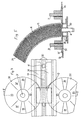
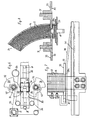
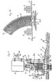
- FIGS. 2-5 show an embodiment of the invention Collection and grouping device shown.
- the transport organ 10 consists of a rotating around sprockets 26 Chain 27, the upper run of which forms the working section 28.
- the Fingers 18 are attached to the chain 27. They take hold of you Longitudinal slot 29 of a sliding surface serving as a collection guide 30, on which the forming groups 11 of disks 12 are advanced.
- the switchable support means on lower ends of the shafts 16a-c are about vertical axes 31 rotatable disks 32.
- the disks 32 have on their top at least two axially spaced apart in radial planes arranged support surfaces 33, 34, which are helical Inclined surfaces 35 are interconnected.
- each Disk pair is by the servo motor 17a-c in question driven.
- the other axis of the pair is mechanical with this an axis coupled for opposite, synchronous rotation, e.g. via pulleys 36 by means of a toothed belt 37 or a chain.
- Downstream of the disks are above the sliding surfaces 30 arranged two inclined sliding plates 38. Their the top margin is slightly below the level of the deepest Support surface 33.
- the lower, downstream edge of the sliding plates 38 is in the successively connected shafts 16a-c progressively higher.
- the sliding surfaces 30 are laterally through side guides 39 limited to the leadership of the forming groups 11.
- FIG. 3 shows the entry end of the packaging machine 13 indicated schematically. Wrapping material is made from a supply roll 43 44 deducted and by means of a not shown Folding box folded around groups 11. The downstream Sprocket 26 is in the area of this folding box. The Longitudinal edges of the film are then sealed, after which in the transverse sealing between the groups 11 follows in a known manner.
- the device described works e.g. how follows: One of the disk pairs 32 is rotated so that the lowest Product 12 in the relevant shaft 16 on the lower one Support surface 33 rests and two products 12 are pushed out become. The other pairs of disks 32 are rotated so that the lowest product 12 on the upper contact surface 34 rests and only a single product 12 is pushed out. It groups 11 of four products 12 are thus formed. In normal operation, if all shafts 16 are fed evenly, the detection of two products will be equally on the three Manholes 16 distributed by the disks 32 periodically through 90 ° be rotated.
- the device By adjusting the height of the shafts 16 and discs 32 can the device can also be operated so that only one Products 12 or none is pushed out, which is indicated in Figure 5 is.
- the disks 32 are replaced by those, the contact surfaces 33, 34 at three different levels so that either no or one product or two products pushed out can be.
- the device is therefore very flexible and easily adaptable to changing operating conditions.
- the device enables high performance with gentle treatment and optional loading performance from the various Manholes.
- more than three shafts can also be used 16 can be provided with associated switching means.
- the second embodiment according to FIGS. 6-8 differs mainly from that of Figures 2-5 in that the Disks 32 only a single bearing surface lying in a radial plane 33 but two diametrically opposite recesses 47 have.
- the thickness of the disc 32 is somewhat less than twice the product thickness.
- the two sliding plates 38 extend with a horizontal portion 38a below the Shaft 16 immediately below the disk 32.
- the disks 32 are either rotated so that one the bearing surface 33 is under the shaft 16 ( Figure 8).
- Figure 8 no products 12 are removed from the fingers 18 Slot 16 pushed out.
- the other position there is a recess 47 below the shaft, making the bottom products 16 rests on the sliding plate section 38a (FIG. 7).
- the fingers 18 two products 12 each pushed out the shaft 16.
- Switching from this to the the first position occurs when a finger 18 passes through such that the bearing surfaces 33 under the stack 24 of products 12 can be pushed in the shaft 16 while it is still is supported by the two products 12 just pushed out (Figure 6).
- This embodiment is especially for less sensitive Products 12 suitable.
- the slice thickness can also be chosen so that only a product 12 is pushed out.
- the two opposite Wings of the disks 32 with the bearing surfaces 33 can also be different be formed thick by the one only approximately the thickness of a product is 12. In this case, you can either 0, 1 or 2 products 12 can be pushed out.
- Also at the embodiment according to FIGS. 6-8 can have two or more Shafts arranged one behind the other along the transport member 10 become.
- the adjustable support means at the lower end of the shafts 16 also vertically, e.g. by means of pneumatic cylinders, in two or more stages accordingly of the product thickness adjustable support surfaces.
- FIGS. 9 and 10 Another embodiment is corresponding in FIGS. 9 and 10 that shown in Figures 6 to 8, so with recesses 47 of the disks 32 and horizontal sliding plate sections 38a, which extend under the shafts 16.
- the diameter the contact surfaces 33 is smaller in this case than in the Embodiment according to Figures 6 to 8 and the sliding sheet sections 38a are narrower and outside the periphery of the contact surfaces 33 arranged.
- both the sliding plate sections 38a as well as the disks 32 in height adjustable.
- the sections 38a are on a carrier 50 mounted by means of a parallelogram linkage 51 on Manhole 16 is vertically movable.
- the carrier is 50 by means of a drive 52, for example a pneumatic cylinder, limited by two adjustable stops 53 vertically slidable.
- the stroke between the stops 53 is set so that it is equal to the thickness of a product 12.
- two products 12 in the upper a product 12 is pushed out when the disks 32 are rotated so are that the recesses 47 are below the shaft 16.
- the Sliding plate section 38a is over with the inclined sliding plate 38 a hinge 54 connected.
- the motor 17 and the two assigned to the same shaft 16 Axes 31 are mounted on a further carrier 56, which by means of a linear guide 57 on the shaft 16 vertically between two adjustable stops 58 is movably mounted.
- the carrier 56 is with another drive 59, for example a pneumatic cylinder connected.
- the stops 58 are set so that the stroke of the carrier 56 is slightly more than twice the thickness of the products 12, and that the bearing surface 33 in the lower End position slightly below the top of the slide plate sections 38a is in its lower position.
- This embodiment is therefore particularly suitable for sensitive Products, for example for rectangular biscuits, in their Vulnerability along the middle for easy breaking in have two halves. There can either be none or one product 12 or two products 12 can be pushed out.
- the carrier 50 also in two stages according to the thickness of the products 12 be adjustable.
- the drives 52, 59 can for example Servomotors with angle encoders that drive threaded spindles which engage in nuts attached to the brackets 50, 56.
- the stroke of the carrier 56 will be something in this case set more than three times the product thickness. In this embodiment can either none or a product 12 or two or three products 12 are pushed out.
- the stroke speeds the carriers 50, 56 are from zero to maximum and back to zero by known electrical or mechanical Medium reached.
- FIG. 9 Another alternative is shown in FIG. 9 with dashed lines shown for the height adjustment of the discs 32.
- the carrier 56 is rigidly connected to the shaft 16 and the drive 59 and the stops 58 and the guide 57 dropped.
- the lower part 31a of the axles 31 is with the upper one Part via a clutch 62 rotatably but axially displaceable connected.
- a cam 63 is rigidly connected to part 31a, which runs in a fixed guide curve 64.
- the hub of the Disks 32 is thus coupled to their rotational movement.
- the leadership curve 64 is designed to reach just before the position in which the rear edge of the Support surface 33 under the upstream edge of the shaft 16 arrives, the discs 32 lowered and the bottom product 12 is placed on the sliding plate section 38a.
- the disks 32 are then rotated further into the position where the recess 47 comes to rest under the shaft 16. At the passage of the next fingers 18, the disks are rotated again by 180 ° and initially raised by the guide curve so that the Discs 32 are in the up position when the leading edge the relevant bearing surface 33 under the rear edge of the shaft reached.
- the number of ejected Products 12 can only be selected according to the number of levels, between which the carrier 50 can be adjusted in height can. This variant has the advantage that it is easier and cheaper is.
Landscapes
- Engineering & Computer Science (AREA)
- Mechanical Engineering (AREA)
- Branching, Merging, And Special Transfer Between Conveyors (AREA)
Description
- Figur 1
- Ein Schema der Steuereinrichtung der Vorrichtung,
- Figur 2
- eine Draufsicht auf eine erste Ausführungsform,
- Figur 3
- eine Seitenansicht,
- Figur 4
- eine Draufsicht auf ein Detail in vergrössertem Massstab,
- Figur 5
- einen Querschnitt längs der Linie V-V in Figur 4
- Figur 6
- eine Draufsicht auf ein Detail einer zweiten Ausführungsform,
- Figur 7
- eine Seitenansicht,
- Figur 8
- einen Querschnitt, und
- Figuren 9 und 10
- eine weitere Ausführungsform.
Claims (12)
- Vorrichtung zum Bilden von Gruppen (11) von aufeinander liegenden, scheibenförmigen Produkten (12), wobei die Vorrichtung ein Transportorgan (10) mit abstehenden Fingern (18) aufweist, um die sich bildenden Gruppen (11) auf einer oberen, annähernd horizontalen Arbeitsstrecke (28) in Transportrichtung (A) zu schieben, wobei oberhalb der Arbeitsstrecke (28) mehrere in Transportrichtung (A) hintereinander angeordnete Schächte (16) angeordnet sind, welche Stapel (24) flach aufeinander liegender Produkte (12) enthalten und beabstandet oberhalb der Arbeitsstrecke (28) enden, wobei die Finger (18) jeweils eine Anzahl von Produkten (12) aus dem unteren Ende der Schächte (16) ausschieben, dadurch gekennzeichnet, dass am unteren Ende der Schächte (16) verstellbare Unterstellmittel (32, 38a) angeordnet sind, welche durch steuerbare Antriebsmittel (17, 52) einzeln in mindestens zwei Stellungen verstellbar sind, in welchen sich das untere Ende der Stapel (24) auf unterschiedlicher Höhe befindet, dass jedem Schacht (16) ein Fühler (23) zugeordnet ist, welcher die An- oder Abwesenheit des Stapels (24) im betreffenden Schacht (16) bis zur Position des Fühlers misst, und dass alle Fühler (23) mit einer gemeinsamen Steuereinrichtung (22) verbunden sind, welche die Antriebsmittel (17, 52) der einzelnen Schächte (16) derart steuert, dass eine ungleichmässige Zufuhr von Produkten (12) zu den Schächten (16) automatisch ausgeglichen wird.
- Vorrichtung nach Anspruch 1, wobei eine der Stellungen derart gewählt ist, dass die Unterseite des betreffenden Stapels (24) oberhalb der Oberkante der durchlaufenden Finger (18) ist.
- Vorrichtung nach Anspruch 1 oder 2, wobei die Unterstellmittel (32) auf beiden Seiten der Arbeitsstrecke (28) angeordnet sind.
- Vorrichtung nach einem der Ansprüche 1 bis 3, wobei die Unterstellmittel durch Scheiben (32) gebildet sind, welche um Achsen (31) drehbar sind, welche vorzugsweise senkrecht sind.
- Vorrichtung nach Anspruch 4, wobei an jedem Schachtende zwei Scheiben (32) angeordnet sind, welche gegenläufig synchron drehbar sind.
- Vorrichtung nach Anspruch 4 oder 5, wobei die Scheiben (32) mindestens zwei in Achsrichtung gegeneinander abgestufte Auflageflächen (33, 34) aufweisen.
- Vorrichtung nach einem der Ansprüche 4 bis 6, wobei die Scheiben (32) mindestens eine Ausnehmung (47) aufweisen und unterhalb der Schächte (16) Auflageelemente (38a) als Anschlag für den betreffenden Stapel (24) angeordnet sind.
- Vorrichtung nach Anspruch 7, wobei die Auflageelemente (38a) durch einen steuerbaren Antrieb (52) in mindestens einer Stufe in der Höhe verstellbar sind.
- Vorrichtung nach Anspruch 7 oder 8, wobei die Scheiben (32) durch Hubelemente (59, 63, 64) parallel zu ihren Achsen (31) verstellbar sind.
- Vorrichtung nach einem der Ansprüche 1 bis 3, wobei die Unterstellmittel horizontale, in der Höhe verstellbare Gleitblechabschnitte (38a) sind.
- Vorrichtung nach einem der Ansprüche 1 bis 10, wobei die Antriebsmittel (17) Servomotoren sind.
- Vorrichtung nach einem der Ansprüche 1 bis 11, wobei stromabwärts mindestens der ersten Schächte (16) geneigt zur Transportrichtung (A) verlaufende Gleitelemente (38) angeordnet sind.
Applications Claiming Priority (4)
| Application Number | Priority Date | Filing Date | Title |
|---|---|---|---|
| CH355795 | 1995-12-15 | ||
| CH355795 | 1995-12-15 | ||
| CH3557/95 | 1995-12-15 | ||
| PCT/CH1996/000423 WO1997022521A1 (de) | 1995-12-15 | 1996-12-02 | Vorrichtung zum bilden von gruppen von aufeinanderliegenden, scheibenförmigen produkten |
Publications (2)
| Publication Number | Publication Date |
|---|---|
| EP0868349A1 EP0868349A1 (de) | 1998-10-07 |
| EP0868349B1 true EP0868349B1 (de) | 2000-02-16 |
Family
ID=4258560
Family Applications (1)
| Application Number | Title | Priority Date | Filing Date |
|---|---|---|---|
| EP96938898A Expired - Lifetime EP0868349B1 (de) | 1995-12-15 | 1996-12-02 | Vorrichtung zum bilden von gruppen von aufeinanderliegenden, scheibenförmigen produkten |
Country Status (4)
| Country | Link |
|---|---|
| US (1) | US6189678B1 (de) |
| EP (1) | EP0868349B1 (de) |
| AU (1) | AU7616996A (de) |
| WO (1) | WO1997022521A1 (de) |
Cited By (2)
| Publication number | Priority date | Publication date | Assignee | Title |
|---|---|---|---|---|
| NL1036007C (nl) * | 2008-10-02 | 2010-04-06 | Machf Houdijk B V | Inrichting voor het op elkaar stapelen van een aantal schijfvormige produkten. |
| US10173849B2 (en) | 2017-02-01 | 2019-01-08 | Bosch Packaging Technology, Inc. | Method and system for extracting articles |
Families Citing this family (8)
| Publication number | Priority date | Publication date | Assignee | Title |
|---|---|---|---|---|
| US6543989B1 (en) * | 1999-07-06 | 2003-04-08 | Kraft Foods Holdings, Inc. | Lowering arms stacking apparatus |
| US6640523B2 (en) * | 2001-05-31 | 2003-11-04 | Kraft Foods Holdings, Inc. | Article gauge and proportional shifter system |
| ITMI20020604A1 (it) * | 2002-03-22 | 2003-09-22 | Otem Pak 2K S R L | Metodo di ordinamento e raggruppamento di prodotti piani |
| DK176572B1 (da) * | 2004-10-21 | 2008-09-22 | Gram Equipment As | Anordning til fremföring af pinde i et apparat til indsætning af pinde i iskremlegemer |
| ITTO20120211A1 (it) * | 2012-03-09 | 2013-09-10 | Sps Italiana Pack Systems S P A | Apparecchiatura per la movimentazione ed il raggruppamento di prodotti piatti |
| DE102019205723A1 (de) * | 2019-04-18 | 2020-10-22 | Syntegon Packaging Systems Ag | Magazinvorrichtung |
| AU2020372336B2 (en) * | 2019-10-21 | 2023-12-07 | Graphic Packaging International, Llc | Method and system for arranging articles |
| GB202015189D0 (en) * | 2020-09-25 | 2020-11-11 | Johnson Matthey Davy Technologies Ltd | Improvements in or relating to tubular reactors |
Family Cites Families (15)
| Publication number | Priority date | Publication date | Assignee | Title |
|---|---|---|---|---|
| US1092613A (en) * | 1910-12-17 | 1914-04-07 | Continental Can Co | Mechanism for feeding can ends. |
| US1126194A (en) * | 1912-08-12 | 1915-01-26 | American Can Co | Automatic feed for sheet-metal can-heads. |
| US1722048A (en) * | 1926-02-26 | 1929-07-23 | Edward C Fritz | Carton holder and delivery mechanism for dispensing machines |
| US2872020A (en) * | 1956-06-05 | 1959-02-03 | Hansel Otto | Stacking apparatus |
| DE1145537B (de) * | 1960-11-10 | 1963-03-14 | Otto Haensel Junior G M B H Sp | Vorrichtung zum Bilden von verpackungsfaehigen Stapeln aus flachen, leicht zerbrechlichen Teilen, wie Keksen, Biskuits, Schokoladetaefelchen od. dgl. |
| CH400892A (de) | 1963-05-08 | 1965-10-15 | Sig Schweiz Industrieges | Vorrichtung zum Gruppieren und Zuführen von Gegenständen |
| GB1111619A (en) * | 1965-02-08 | 1968-05-01 | Baker Perkins Ltd | Improvements relating to the handling of biscuits |
| US3625384A (en) * | 1968-09-26 | 1971-12-07 | Ibm | Article-handling apparatus |
| CH582601A5 (de) * | 1974-09-18 | 1976-12-15 | Sig Schweiz Industrieges | |
| US3978571A (en) * | 1974-10-21 | 1976-09-07 | Globe-Union Inc. | Apparatus for assembling storage battery plates and separators |
| DE2544754C2 (de) * | 1975-10-07 | 1982-08-05 | Benz & Hilgers GmbH, 4000 Düsseldorf | Vorrichtung zur Entnahme ineinander gestapelter Gegenstände |
| US4421019A (en) * | 1982-08-16 | 1983-12-20 | Eskimo Pie Corporation | Cookie dispensing apparatus |
| US4547114A (en) * | 1982-09-29 | 1985-10-15 | The Procter & Gamble Company | Positive control stacker |
| IT1260039B (it) * | 1992-02-24 | 1996-03-28 | Metodo di transito per piccoli oggetti all'interno di camere di trattamento, e suoi mezzi attuatori | |
| IT1285438B1 (it) * | 1996-01-09 | 1998-06-08 | Azionaria Costruzioni Acma Spa | Metodo ed unita' per la formazione di pile di articoli |
-
1996
- 1996-12-02 WO PCT/CH1996/000423 patent/WO1997022521A1/de not_active Ceased
- 1996-12-02 EP EP96938898A patent/EP0868349B1/de not_active Expired - Lifetime
- 1996-12-02 AU AU76169/96A patent/AU7616996A/en not_active Abandoned
-
1998
- 1998-06-11 US US09/095,658 patent/US6189678B1/en not_active Expired - Lifetime
Cited By (3)
| Publication number | Priority date | Publication date | Assignee | Title |
|---|---|---|---|---|
| NL1036007C (nl) * | 2008-10-02 | 2010-04-06 | Machf Houdijk B V | Inrichting voor het op elkaar stapelen van een aantal schijfvormige produkten. |
| EP2172398A1 (de) * | 2008-10-02 | 2010-04-07 | B.V. Machinefabriek Houdijk | Vorrichtung zum Stapeln mehrerer plattenförmiger Produkte |
| US10173849B2 (en) | 2017-02-01 | 2019-01-08 | Bosch Packaging Technology, Inc. | Method and system for extracting articles |
Also Published As
| Publication number | Publication date |
|---|---|
| EP0868349A1 (de) | 1998-10-07 |
| US6189678B1 (en) | 2001-02-20 |
| WO1997022521A1 (de) | 1997-06-26 |
| AU7616996A (en) | 1997-07-14 |
Similar Documents
| Publication | Publication Date | Title |
|---|---|---|
| DE60311778T2 (de) | Zurückziehbare übergabeeinrichtung für eine dosiervorrichtung | |
| DE69121230T2 (de) | Einrichtung zum Verteilen und Sammeln von zu fördernden Produkten | |
| DE4013687C2 (de) | Förderanlage für Packungen mit integriertem Pufferspeicher | |
| DE69708027T2 (de) | Auswahlanordnung | |
| EP0453407A1 (de) | Verfahren und Vorrichtung zur Bildung von Gruppen von Nahrungsmittelscheiben | |
| EP0076939B1 (de) | Einrichtung zur Bildung und Abgabe von Päckchen aus mehreren, flächigen Einzelerzeugnissen aus Papier, Zellstoffwatte od. dgl. | |
| EP0788986B1 (de) | Scheibenstapler, insbesondere für Käsescheiben | |
| DE4017692C2 (de) | ||
| EP0619229B1 (de) | Vorrichtung zum Aufteilen scheibenförmiger Produkte auf mehrere Ausgangskolonnen | |
| DE3151017C2 (de) | ||
| EP0283670B1 (de) | Gruppiereinrichtung zur Bildung von Behältergruppen | |
| DE3715570C2 (de) | ||
| DE2245515B2 (de) | Stapelvorrichtung zum Aufsetzen und Austragen von Tütenstapeln | |
| EP0868349A1 (de) | Vorrichtung zum bilden von gruppen von aufeinanderliegenden, scheibenförmigen produkten | |
| DE69717329T2 (de) | Vorrichtung zur Aufteilung und Einstellung eines Produktstromes in eine Vielzahl unterteilter Reihen | |
| DE3122733A1 (de) | Vorrichtung zur verteilung von aus einem einreihigen foerderer kommenden behaeltern auf einen mehrreihigen foerderer | |
| DE69610636T2 (de) | Vorrichtung zum verpacken von mit dornen versehenen platten oder dergleichen | |
| EP0508304A1 (de) | Vorrichtung zum Transport eines aus einer oder wenigen Reihen ankommenden Gutes in eine andere, insbesondere grössere, Zahl von Transportreihen | |
| DE2438780B2 (de) | Vorrichtung zum Ausrichten und Überführen in gleiche Abstände von in unregelmäßigen Reihen aus einer Herstellungsmaschine kommenden Gegenständen | |
| EP0526403A1 (de) | Verfahren und Vorrichtung zur Bildung von Gruppen von Nahrungsmittelscheiben | |
| DE602004004205T2 (de) | Automatisches System zum Sortieren und Palettieren von Artikeln | |
| DE68907213T2 (de) | Foerdersystem. | |
| DE2900139C3 (de) | Walzenförderer | |
| DE69800411T2 (de) | Maschine zum Verpacken von Zigarettengruppen | |
| DE2433547C3 (de) | Vorrichtung zum Abbrechen von Streifen von Platten |
Legal Events
| Date | Code | Title | Description |
|---|---|---|---|
| PUAI | Public reference made under article 153(3) epc to a published international application that has entered the european phase |
Free format text: ORIGINAL CODE: 0009012 |
|
| 17P | Request for examination filed |
Effective date: 19980508 |
|
| AK | Designated contracting states |
Kind code of ref document: A1 Designated state(s): CH IT LI NL |
|
| 17Q | First examination report despatched |
Effective date: 19981026 |
|
| GRAG | Despatch of communication of intention to grant |
Free format text: ORIGINAL CODE: EPIDOS AGRA |
|
| GRAG | Despatch of communication of intention to grant |
Free format text: ORIGINAL CODE: EPIDOS AGRA |
|
| GRAH | Despatch of communication of intention to grant a patent |
Free format text: ORIGINAL CODE: EPIDOS IGRA |
|
| GRAH | Despatch of communication of intention to grant a patent |
Free format text: ORIGINAL CODE: EPIDOS IGRA |
|
| GRAA | (expected) grant |
Free format text: ORIGINAL CODE: 0009210 |
|
| AK | Designated contracting states |
Kind code of ref document: B1 Designated state(s): CH IT LI NL |
|
| REG | Reference to a national code |
Ref country code: CH Ref legal event code: NV Representative=s name: ISLER & PEDRAZZINI AG Ref country code: CH Ref legal event code: EP |
|
| ITF | It: translation for a ep patent filed | ||
| EN | Fr: translation not filed | ||
| PGFP | Annual fee paid to national office [announced via postgrant information from national office to epo] |
Ref country code: CH Payment date: 20001025 Year of fee payment: 5 |
|
| PLBE | No opposition filed within time limit |
Free format text: ORIGINAL CODE: 0009261 |
|
| STAA | Information on the status of an ep patent application or granted ep patent |
Free format text: STATUS: NO OPPOSITION FILED WITHIN TIME LIMIT |
|
| 26N | No opposition filed | ||
| PG25 | Lapsed in a contracting state [announced via postgrant information from national office to epo] |
Ref country code: LI Free format text: LAPSE BECAUSE OF NON-PAYMENT OF DUE FEES Effective date: 20011231 Ref country code: CH Free format text: LAPSE BECAUSE OF NON-PAYMENT OF DUE FEES Effective date: 20011231 |
|
| REG | Reference to a national code |
Ref country code: CH Ref legal event code: PL |
|
| PGFP | Annual fee paid to national office [announced via postgrant information from national office to epo] |
Ref country code: NL Payment date: 20121217 Year of fee payment: 17 |
|
| PGFP | Annual fee paid to national office [announced via postgrant information from national office to epo] |
Ref country code: IT Payment date: 20131218 Year of fee payment: 18 |
|
| REG | Reference to a national code |
Ref country code: NL Ref legal event code: V1 Effective date: 20140701 |
|
| PG25 | Lapsed in a contracting state [announced via postgrant information from national office to epo] |
Ref country code: NL Free format text: LAPSE BECAUSE OF NON-PAYMENT OF DUE FEES Effective date: 20140701 |
|
| PG25 | Lapsed in a contracting state [announced via postgrant information from national office to epo] |
Ref country code: IT Free format text: LAPSE BECAUSE OF NON-PAYMENT OF DUE FEES Effective date: 20141202 |