EP0864738B1 - Commande d'injection de carburant pour moteurs diesel - Google Patents
Commande d'injection de carburant pour moteurs diesel Download PDFInfo
- Publication number
- EP0864738B1 EP0864738B1 EP98104176A EP98104176A EP0864738B1 EP 0864738 B1 EP0864738 B1 EP 0864738B1 EP 98104176 A EP98104176 A EP 98104176A EP 98104176 A EP98104176 A EP 98104176A EP 0864738 B1 EP0864738 B1 EP 0864738B1
- Authority
- EP
- European Patent Office
- Prior art keywords
- fuel
- combustion chamber
- combustion
- control unit
- electronic control
- Prior art date
- Legal status (The legal status is an assumption and is not a legal conclusion. Google has not performed a legal analysis and makes no representation as to the accuracy of the status listed.)
- Expired - Lifetime
Links
Images


Classifications
-
- F—MECHANICAL ENGINEERING; LIGHTING; HEATING; WEAPONS; BLASTING
- F02—COMBUSTION ENGINES; HOT-GAS OR COMBUSTION-PRODUCT ENGINE PLANTS
- F02M—SUPPLYING COMBUSTION ENGINES IN GENERAL WITH COMBUSTIBLE MIXTURES OR CONSTITUENTS THEREOF
- F02M45/00—Fuel-injection apparatus characterised by having a cyclic delivery of specific time/pressure or time/quantity relationship
- F02M45/02—Fuel-injection apparatus characterised by having a cyclic delivery of specific time/pressure or time/quantity relationship with each cyclic delivery being separated into two or more parts
- F02M45/04—Fuel-injection apparatus characterised by having a cyclic delivery of specific time/pressure or time/quantity relationship with each cyclic delivery being separated into two or more parts with a small initial part, e.g. initial part for partial load and initial and main part for full load
-
- F—MECHANICAL ENGINEERING; LIGHTING; HEATING; WEAPONS; BLASTING
- F02—COMBUSTION ENGINES; HOT-GAS OR COMBUSTION-PRODUCT ENGINE PLANTS
- F02D—CONTROLLING COMBUSTION ENGINES
- F02D35/00—Controlling engines, dependent on conditions exterior or interior to engines, not otherwise provided for
- F02D35/02—Controlling engines, dependent on conditions exterior or interior to engines, not otherwise provided for on interior conditions
- F02D35/021—Controlling engines, dependent on conditions exterior or interior to engines, not otherwise provided for on interior conditions using an ionic current sensor
-
- F—MECHANICAL ENGINEERING; LIGHTING; HEATING; WEAPONS; BLASTING
- F02—COMBUSTION ENGINES; HOT-GAS OR COMBUSTION-PRODUCT ENGINE PLANTS
- F02D—CONTROLLING COMBUSTION ENGINES
- F02D41/00—Electrical control of supply of combustible mixture or its constituents
- F02D41/008—Controlling each cylinder individually
-
- F—MECHANICAL ENGINEERING; LIGHTING; HEATING; WEAPONS; BLASTING
- F02—COMBUSTION ENGINES; HOT-GAS OR COMBUSTION-PRODUCT ENGINE PLANTS
- F02D—CONTROLLING COMBUSTION ENGINES
- F02D41/00—Electrical control of supply of combustible mixture or its constituents
- F02D41/30—Controlling fuel injection
- F02D41/38—Controlling fuel injection of the high pressure type
- F02D41/3809—Common rail control systems
- F02D41/3818—Common rail control systems for petrol engines
-
- F—MECHANICAL ENGINEERING; LIGHTING; HEATING; WEAPONS; BLASTING
- F02—COMBUSTION ENGINES; HOT-GAS OR COMBUSTION-PRODUCT ENGINE PLANTS
- F02D—CONTROLLING COMBUSTION ENGINES
- F02D41/00—Electrical control of supply of combustible mixture or its constituents
- F02D41/30—Controlling fuel injection
- F02D41/38—Controlling fuel injection of the high pressure type
- F02D41/3809—Common rail control systems
- F02D41/3827—Common rail control systems for diesel engines
-
- F—MECHANICAL ENGINEERING; LIGHTING; HEATING; WEAPONS; BLASTING
- F02—COMBUSTION ENGINES; HOT-GAS OR COMBUSTION-PRODUCT ENGINE PLANTS
- F02D—CONTROLLING COMBUSTION ENGINES
- F02D41/00—Electrical control of supply of combustible mixture or its constituents
- F02D41/30—Controlling fuel injection
- F02D41/38—Controlling fuel injection of the high pressure type
- F02D41/40—Controlling fuel injection of the high pressure type with means for controlling injection timing or duration
- F02D41/402—Multiple injections
- F02D41/403—Multiple injections with pilot injections
-
- F—MECHANICAL ENGINEERING; LIGHTING; HEATING; WEAPONS; BLASTING
- F02—COMBUSTION ENGINES; HOT-GAS OR COMBUSTION-PRODUCT ENGINE PLANTS
- F02P—IGNITION, OTHER THAN COMPRESSION IGNITION, FOR INTERNAL-COMBUSTION ENGINES; TESTING OF IGNITION TIMING IN COMPRESSION-IGNITION ENGINES
- F02P19/00—Incandescent ignition, e.g. during starting of internal combustion engines; Combination of incandescent and spark ignition
- F02P19/02—Incandescent ignition, e.g. during starting of internal combustion engines; Combination of incandescent and spark ignition electric, e.g. layout of circuits of apparatus having glowing plugs
- F02P19/028—Incandescent ignition, e.g. during starting of internal combustion engines; Combination of incandescent and spark ignition electric, e.g. layout of circuits of apparatus having glowing plugs the glow plug being combined with or used as a sensor
-
- F—MECHANICAL ENGINEERING; LIGHTING; HEATING; WEAPONS; BLASTING
- F02—COMBUSTION ENGINES; HOT-GAS OR COMBUSTION-PRODUCT ENGINE PLANTS
- F02B—INTERNAL-COMBUSTION PISTON ENGINES; COMBUSTION ENGINES IN GENERAL
- F02B3/00—Engines characterised by air compression and subsequent fuel addition
- F02B3/06—Engines characterised by air compression and subsequent fuel addition with compression ignition
-
- F—MECHANICAL ENGINEERING; LIGHTING; HEATING; WEAPONS; BLASTING
- F02—COMBUSTION ENGINES; HOT-GAS OR COMBUSTION-PRODUCT ENGINE PLANTS
- F02D—CONTROLLING COMBUSTION ENGINES
- F02D2200/00—Input parameters for engine control
- F02D2200/02—Input parameters for engine control the parameters being related to the engine
- F02D2200/04—Engine intake system parameters
- F02D2200/0406—Intake manifold pressure
-
- F—MECHANICAL ENGINEERING; LIGHTING; HEATING; WEAPONS; BLASTING
- F02—COMBUSTION ENGINES; HOT-GAS OR COMBUSTION-PRODUCT ENGINE PLANTS
- F02D—CONTROLLING COMBUSTION ENGINES
- F02D41/00—Electrical control of supply of combustible mixture or its constituents
- F02D41/30—Controlling fuel injection
- F02D41/38—Controlling fuel injection of the high pressure type
- F02D41/3809—Common rail control systems
-
- Y—GENERAL TAGGING OF NEW TECHNOLOGICAL DEVELOPMENTS; GENERAL TAGGING OF CROSS-SECTIONAL TECHNOLOGIES SPANNING OVER SEVERAL SECTIONS OF THE IPC; TECHNICAL SUBJECTS COVERED BY FORMER USPC CROSS-REFERENCE ART COLLECTIONS [XRACs] AND DIGESTS
- Y02—TECHNOLOGIES OR APPLICATIONS FOR MITIGATION OR ADAPTATION AGAINST CLIMATE CHANGE
- Y02T—CLIMATE CHANGE MITIGATION TECHNOLOGIES RELATED TO TRANSPORTATION
- Y02T10/00—Road transport of goods or passengers
- Y02T10/10—Internal combustion engine [ICE] based vehicles
- Y02T10/40—Engine management systems
Definitions
- the present invention relates to fuel injection controllers for diesel engines, and more particularly, to apparatuses that controls fuel injection based on ion currents produced during the combustion of fuel.
- a typical diesel engine installed in automobiles has a plurality of reciprocal pistons that are housed in a cylinder block. Each piston is connected to a crankshaft (output shaft) of the engine by a connecting rod. The connecting rod converts the reciprocation of each piston to rotation of the crankshaft.
- a cylinder head is arranged on the cylinder block to define a combustion chamber between the head of each piston and the cylinder head.
- An intake manifold and an exhaust manifold, which communicate with each combustion chamber, extend through the cylinder head.
- a fuel injector is provided for each combustion chamber in the cylinder head. The fuel injector injects fuel into the associated combustion chamber.
- each piston air is drawn into the associated combustion chamber by way of the intake manifold.
- the piston moves from its bottom dead center to its top dead center. This compresses the air in the combustion chamber.
- the fuel injector injects atomized fuel into the combustion chamber. The heat produced by the compression of air ignites and burns the fuel. This forces the piston toward the bottom dead center from the top dead center to perform the power stroke.
- the piston moves from the bottom dead center to the top dead center. This pushes the burned gases (exhaust gas) out of the combustion chamber and into the exhaust manifold.
- the ignition timing is varied by changing the injection timing.
- the ignition timing may be shifted to an optimal timing value by controlling the injection timing.
- Japanese Unexamined Patent Publication No. 59-160046 describes such a fuel injection timing controller for diesel engines.
- the controller includes a glow plug for each combustion chamber.
- the glow plug also functions as an ion current detector. Ions are formed when fuel is burned in each combustion chamber. The ions produce electric current (ion current), which is detected by the associated glow plug. Signals corresponding to the detected current value are output from the glow plug.
- the controller also includes a crank sensor that detects a projection on the crankshaft. The crank sensor outputs a signal when detecting the projection. Thus, pulse signals are output from the crank sensor during rotation of the crankshaft.
- the controller determines the ignition timing in each combustion chamber from the glow plug and crank sensor signals. The controller then optimizes the ignition timing by adjusting the injection timing. The injection timing control maintains satisfactory combustion in the combustion chamber and stabilizes the operation of the diesel engine.
- the fuel combustion time which varies in accordance with the amount of injected fuel, influences the combustion state in each combustion chamber.
- the controller of the above publication controls the injection timing to optimize the ignition timing, the combustion time is not optimized. Therefore, the combustion state may be unsatisfactory due to an improper amount of fuel injection. This produces fumes in the exhaust gas and degrades engine emissions.
- Different combustion times between different combustion chambers may also result in differing combustion states between combustion chambers.
- the different combustion states may vibrate the diesel engine and degrade the driving performance of the engine.
- the ignition timing may differ in each combustion chamber. This may lead to different combustion states between combustion chambers thus increasing the noise produced by the diesel engine.
- the present invention provides an apparatus for controlling a fuel injection amount in a diesel engine as defined in claim 1.
- a first example of a fuel injection amount controller will now be described with reference to Figs. 1 to 5.
- the controller which is applied to automobile diesel engines, is outside the scope of the claims, but its functions may be integrated in the second example of a controller discussed below.
- a diesel engine 11 has a cylinder block 11a, which houses four reciprocal pistons 12 (only one shown in Fig. 1). Each piston 12 is connected to a crankshaft (output shaft) 14, which extends through the lower portion of the engine 11, by a connecting rod 13. The connecting rod 13 converts the reciprocation of each piston 12 to rotation of the crankshaft 14.
- a crank signal rotor 15 is fitted to the crankshaft 14.
- a plurality of equally spaced projections 15a extend radially, with respect to the axis of the crankshaft 14, from the peripheral surface of the signal rotor 15.
- a crank sensor 16 facing the peripheral surface of the signal rotor 15 detects the projections 15a and outputs signals. As the crankshaft 14 rotates, the projections 15a successively pass by the crank sensor 16. As each projection 15a passes by, the crank sensor 16 outputs a pulse signal.
- a coolant temperature sensor 11b is arranged on the cylinder block 11a to detect the temperature of the coolant flowing through the engine 11.
- a cylinder head 17 is mounted on the cylinder block 11a to define a combustion chamber 18 between the cylinder head 17 and each piston 12.
- a fuel injector 18a is provided for each combustion chamber 18 in the cylinder head 17. The fuel injector 18a injects fuel into the associated combustion chamber 18.
- An intake port 19 and an exhaust port 20 are provided for each combustion chamber 18 in the cylinder head 17.
- An intake valve 21 is arranged in each intake port 19, while an exhaust valve 22 is arranged in each exhaust port 20.
- An intake cam shaft 23, which drives the intake valves 21, and an exhaust cam shaft 22, which drives the exhaust valves 24, are rotatably supported in the cylinder head 17.
- the intake and exhaust camshafts 23 are connected to the crankshaft 14 by a timing belt (not shown). Hence, the rotation of the crankshaft 14 is transmitted to the intake and exhaust camshafts 23, 24 by the timing belt.
- the rotation of the intake camshaft 23 opens and closes each intake valve 21 to selectively connect and disconnect the associated intake port 19 and combustion chamber 18.
- the rotation of the exhaust camshaft 24 opens and closes each exhaust valve 22 to selectively connect and disconnect the associated exhaust port 20 and combustion chamber 18.
- a cam signal rotor 25 is attached to the exhaust camshaft 24.
- a single projection 25a projects from the peripheral surface of the signal rotor 25.
- a cam sensor 26 facing the peripheral surface of the signal rotor 25 detects the projection 25a and outputs a signal. As the camshaft 24 rotates, the projection 25a passes by the cam sensor 26. As each projection 25a passes by, the cam sensor 26 outputs a signal.
- the intake ports 19 are connected to an intake manifold 30, while the exhaust ports 20 are connected to an exhaust manifold 31.
- the intake manifold 30 and the intake ports 19 define an intake passage 32.
- the exhaust manifold 31 and the exhaust ports 20 define an exhaust passage 33.
- a throttle valve 34 is located at the upstream portion of the intake passage 32. The angle of the throttle valve 34 is adjusted in accordance with the depression amount (or depression angle) of an acceleration pedal 35.
- a throttle sensor 36 is located in the vicinity of the throttle valve 34 to detect the angle of the throttle valve 34 and outputs a corresponding signal.
- An intake pressure sensor 37 is located downstream of the throttle valve 34 in the intake manifold 30. The pressure sensor 37 detects the pressure in the intake passage 32 downstream of the throttle valve 34 and outputs a corresponding signal.
- the crankshaft 14 is connected to a drive shaft 41a of a fuel injection pump 41.
- a pipe 42 and a pipe 43 are connected to the injection pump 41.
- the pipes 42, 43 lead to a fuel reservoir 44.
- the fuel reservoir 44 is connected to each fuel injector 18a by a fuel line 45.
- Fuel is injected into each combustion chamber 18 during the final stage of the compression stroke.
- the heat produced by the compression of air ignites and burns the fuel. This produces the drive force of the engine 11.
- the combustion products, or exhaust gases, are sent out through the exhaust passage 33.
- the cylinder block 11a includes four cylinders (#1, #2, #3, #4). Each cylinder #1-#4 is provided with a combustion chamber 18 and a fuel injector 18a. A swirl chamber 52 is provided for each combustion chamber 18 in the cylinder head 17. The swirl chamber 52 is communicated with the associated combustion chamber 18.
- Each fuel injector 18a includes an electromagnetic solenoid 51. The fuel injector 18a is opened and closed by a needle (not shown) in accordance with the excitation and de-excitation of the electromagnetic solenoid 51. Thus, the opening and closing of the fuel injector 18a injects fuel intermittently. The fuel injector 18a injects fuel into the swirl chamber 52. The fuel is then burned and sent to the associated combustion chamber 18 from the swirl chamber 52.
- a glow plug 53 is provided for each swirl chamber 52.
- a core 54 and a heater 55 are arranged at the distal end of each glow plug 53.
- the core 54 is made of a conductive material and used to detect ion current.
- the heater 55 is made of a nichrome wire (not shown).
- the core 54 and the heater 55 are insulated from each other and arranged in the swirl chamber 52.
- the core 54 and the heater 55 are also insulated from the wall of the swirl chamber 52.
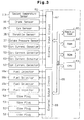
- the fuel injection amount controller has an electronic control unit (ECU) 61 to control the operating state of the engine 11.
- the ECU 61 is a logical operation circuit that includes a read only memory (ROM) 62, a central processing unit (CPU) 63, a random access memory (RAM) 64, and a backup RAM 65.
- the ROM 62 is a memory that stores control programs and maps used to execute the control programs.
- the RAM 64 is a memory that temporarily stores the computations of the CPU 63 and the data sent from the sensors.
- the backup RAM 65 is a nonvolatile memory, which keeps data stored when the engine 11 is not running.
- the ROM 62, the CPU 63, the RAM 64, and the backup RAM 65 are connected to one another by a bus 66.
- the bus 66 is also connected to an external input circuit 67 and an external output circuit 68.
- the external input circuit 67 is connected to the coolant temperature sensor 11b, the crank sensor 16, the cam sensor 26, the throttle sensor 36, the intake pressure sensor 37, and the ion current detectors 53 of the cylinder #1-#4.
- the external output circuit 68 is connected to the fuel injectors 18a and glow plugs 53 of the cylinders #1-#4.
- the control program executed by the ECU 61 will now be described with reference to the flowchart of Fig. 4.
- the flowchart illustrates a routine for computing the fuel injection amount. This routine is executed by the ECU 61 in an interrupting manner for every predetermined crank angle.
- the ECU 61 locates the cylinder in which fuel has just been injected based on the signals sent from the crank sensor 16 and the cam sensor 26. The ECU 61 then sets a cylinder number K that corresponds to the located cylinder. The ECU 61 sets K as one when determining that fuel has just been injected into cylinder #1. K is set to two when the located cylinder is #3, to three when the located cylinder is #4, and to four when the located cylinder is #2.
- Fuel is injected in the order of cylinder #1, cylinder #3, cylinder #4, and cylinder #2.
- K is changed from one, which corresponds to the cylinder #1, to two, which corresponds to the cylinder #3.
- the ions produced during the combustion of the fuel generate ion current between the core 54 of the associated glow plug 53 and the wall of the swirl chamber 52, as shown in Fig. 5(b).
- the ion current is sent to the ECU 61 by the associated glow plug (ion current detector) 53.
- the ECU 61 rectifies the waveform of the ion current, as shown in Fig. 5(c).
- the ECU 61 then proceeds to step S102 and computes the actual combustion time TACTL K of the fuel based on the rectified waveform of the ion current.
- the actual combustion time TACTL K varies in accordance with the amount of fuel injection.
- the ECU 61 determines the present cylinder average combustion time TAV K,i . More specifically, the ECU 61 subtracts the previous average combustion time for that cylinder TAV K,i-1 from the actual combustion time TACTL K obtained in step S102. The ECU 61 then divides the difference by n (n is a constant) and adds the previous average combustion time TAV K,i-1 to obtain the present cylinder average combustion time TAV K,i . Lower case i is used herein to indicate the cycle number for a given cylinder. Thus, each time fuel is injected into a given cylinder, i increases by one.
- the ECU 61 uses the present actual combustion time TACTL K for that cylinder as the previous cylinder average combustion time TAV K,i-1 to obtain the present cylinder average combustion time TAV K,i .
- the ECU 61 then proceeds to step S104.
- step S104 the ECU 61 determines whether or not the fluctuation of the engine speed NE and the depression angle of the acceleration pedal 35 are small based on the signals sent from the crank sensor 16, the cam sensor 26, and the throttle sensor 36. If it is determined that the engine speed fluctuation and the depression angle fluctuation are small, the ECU 61 proceeds to step S105.
- the ECU 61 adds the most recent cylinder average combustion time TAV K,i of each cylinder #1-#4 and divides the sum by the number of cylinders (in this case, four) to compute the total average combustion time TAV TOT ⁇
- the total average combustion time TAV TOT is the average value of the average combustion time TAV K,i for all cylinders #1-#4.
- the ECU 61 sets the total average combustion time TAV TOT as a target value. As the average combustion time TAV K,i of each cylinder #1-#4 approaches the target value, the combustion state in the combustion chamber 18 of each cylinder #1-#4 improves.
- step S106 the ECU 61 proceeds to step S106 and computes the compensation amount Q K,i of the fuel injection amount in each cylinder #1-#4.
- the present compensation amount Q K,i for the current cylinder is computed by subtracting the present cylinder average combustion time TAV K,i from the total average combustion time TAV TOT . The difference is multiplied by a predetermined value b and then added to the previous compensation amount Q K,i-1 for the same cylinder to obtain the present compensation amount Q K,i .
- the present compensation amount Q K,i will be used to compensate the fuel injection amount of the same cylinder in the next cycle (i+1).
- the ECU 61 proceeds to step S107.
- the predetermined value b determines how much the difference between the total average combustion time TAV TOT and the cylinder average combustion time TAV K,i affects the compensation amount Q K,i . If the predetermined value b is greater, the fuel injection compensation amount for the subsequent fuel injection increases in a sudden manner. If the predetermined value b is smaller, the fuel injection compensation amount for the subsequent fuel injection increases in a gradual manner. In a preferred example, the predetermined value b is set so that the fuel injection compensation amount does not increase in a relatively sudden manner.
- step S104 If it is determined that the fluctuation of the engine speed NE and the depression angle is great in step S104, the ECU 61 skips steps S105, S106 and proceeds to step S107. In this case, the ECU 61 uses the previous compensation amount Q K,i-1 to compensate the amount of fuel injected into the current cylinder.
- the ECU 61 obtains a basic fuel injection amount Q bse in correspondence with the operating state of the engine 11, which is based on characteristics such as the engine speed NE and the depression angle, by referring to a map stored in the ROM 62. The map is plotted in accordance with experimental results.
- the ECU 61 then proceeds to step S108 and computes the target fuel injection amount Q fin for the next cylinder in the injection order.
- the target fuel injection amount Q fin is computed by adding the compensation amount Q K,i , which was obtained during the next cylinder's previous fuel injection, to the basic fuel injection amount Q bse .
- Fuel is injected into each cylinder #1-#4 in accordance with its target fuel injection amount Q fin , which is computed as described above. Accordingly, the difference between the average combustion time TAV K,i of each cylinder #1-#4 and the total average combustion time TAV TOT is minimized. This prevents the average combustion time TAV K,i from becoming inappropriate due to an improper amount of fuel injection. As a result, satisfactory combustion of fuel takes place in the combustion chamber 18 of each cylinder #1-#4. Since the difference between the average combustion time TAV K,i of each cylinder #1-#4 and the total average combustion time TAV TOT is minimized, the cylinder average combustion time TAV K,i becomes substantially the same in each cylinder #1-#4. Consequently, the combustion states in all cylinders #1-#4 are substantially the same.
- the actual combustion time TACTL K which is computed based on the ion current sent from the associated glow plug (ion current detector) 53, becomes inappropriate.
- the ECU 61 compensates the fuel injection amount for the next injection cycle to minimize the difference between the cylinder average combustion time TAV K,i and the total average combustion time TAV TOT . Accordingly, the compensation of the amount of fuel injection keeps the cylinder average combustion time TAV K,i at an appropriate value and guarantees satisfactory combustion of fuel in the combustion chamber 18. As a result, the exhaust gas is free from fumes and engine emissions are improved.
- the difference between the average combustion time TAV K,i of each cylinder #1-#4 and the total average combustion time TAV TOT is minimized.
- the cylinder average combustion time TAV K,i becomes substantially the same in each cylinder #1-#4.
- the combustion state in each cylinder #1-#4 becomes substantially the same. This suppresses vibrations that would be produced by cylinders #1-#4 having different combustion states and enhances the driving performance of the engine 11.
- the present fuel injection compensation amount Q K,i s computed when the fluctuation of the engine speed NE and the depression angle of the acceleration pedal 35 is small, that is, when the engine 11 remains in the same operating state. Therefore, the present fuel injection compensation amount Q K,i remains appropriate despite sudden changes in the operating state of the engine 11.
- the previous fuel injection compensation amount Q K,i-I is used during the next fuel injection when the operating state of the engine 11 changes drastically. Thus, the fuel injection amount maintains an appropriate value.
- FIG. 6 A second example of a fuel injection amount controller according to an embodiment of the present invention will now be described with reference to Figs. 6 to 8.
- This example differs from the first example in only the program executed by the ECU 61.
- like or identical corresponding components will be denoted with the same reference numeral and will not be described.
- a small portion of the fuel injection amount is injected into each combustion chamber 18 before injecting the rest of the fuel injection amount.
- the engine 11 performs pilot injection to improve ignition of the main portion of the fuel injected (main injection) into the combustion chamber 18.
- Figs. 6(a) and 6(b) illustrate changes in the ignition timing of the fuel injected into each combustion chamber 18 in correspondence with the pilot injection amount.
- the ignition timing of fuel in each combustion chamber 18 is retarded.
- the timing at which ion current is generated between the core 54 of the associated glow plug 53 and the wall of the combustion chamber 18 is delayed from the desired timing, as shown by the uniformly dashed line in Fig. 6(a).
- the pilot injection amount is excessive as shown by the line made up of long and short dashes in Fig. 6(b)
- the ignition timing is advanced.
- the ion current generation timing is advanced from the desired timing, as shown by the line made up of long and short dashes in Fig. 6(a).
- the control program executed by the ECU 61 in this example will now be described with reference to the flowchart of Fig. 8.
- the flowchart illustrates a routine for computing the pilot fuel injection amount. This routine is executed by the ECU 61 in an interrupting manner for every predetermined crank angle.
- the ECU 61 locates the cylinder in which main injection has just been performed.
- the ECU 61 sets K, which corresponds to the located cylinder.
- the relationship between K and the cylinder number (#1-#4) is set the same way as in the first example.
- the order for performing injection in the cylinders #1-#4 is also the same as in the first example.
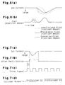
- K is changed from one, which corresponds to cylinder #1, to two, which corresponds to cylinder #3, as shown in Fig. 7(d).
- the ions produced during the combustion of the fuel injected into cylinder #3 generate ion current between the core 54 of the associated glow plug 53 and the wall of the swirl chamber 52, as shown in Fig. 7(a).
- the ion current is sent to the ECU 61 by the associated glow plug (ion current detector) 53.
- the ECU 61 rectifies the waveform of the ion current, as shown in Fig. 7(b).
- the ECU 61 then proceeds to step S202 and computes the actual ignition timing TMACTL K of the fuel in the current cylinder based on the rectified waveform of the ion current and the pulse signals from the crank sensor 16 (Fig. 7(c)).
- the actual ignition timing TMACTL K varies in accordance with the pilot injection amount.
- the ECU 61 determines the present average ignition timing TMAV K,i of the current cylinder. More specifically, the ECU 61 subtracts the previous average ignition timing TMAV K,i-1 of the current cylinder from the actual ignition timing TMACTL K . The ECU 61 then divides the difference by n (n is a constant) and adds the previous average ignition timing TMAV K,i-1 to obtain the present average ignition timing TMAV K,i of the current cylinder.
- the ECU 61 uses the present actual ignition timing TMACTL K as the previous average ignition timing TMAV K,i-1 to obtain the present average ignition timing TMAV K,i .
- the ECU 61 then proceeds to step S204.
- the ECU 61 determines whether or not the engine 11 is idling based on the signals sent from the crank sensor 16, the cam sensor 26, and the throttle sensor 36. If it is determined that the engine 11 is idling, the ECU 61 proceeds to step S205.
- the ECU 61 refers to a map, which is stored in the ROM 62, to obtain the target ignition timing T t in correspondence with the engine speed NE and the depression angle of the acceleration pedal 35.
- the map is plotted in accordance with experimental results.
- the target ignition timing T t is the timing that results in satisfactory combustion when fuel is ignited in the combustion chamber 18.
- the ECU 61 computes the compensation amount QP K,i of the pilot fuel injection amount in each cylinder #1-#4.
- the present compensation amount QP K,i for is computed by subtracting the present cylinder average ignition timing TMAV K,i of the current cylinder from the target ignition timing T t . The difference is multiplied by a predetermined value c and then added to the previous compensation amount QP K,i-1 to obtain the compensation amount QP K,i .
- the present pilot injection compensation amount QP K,i will be used to compensate the pilot injection amount of the current cylinder in the next cycle (i+1).
- the ECU 61 proceeds to step S207.
- the predetermined value c determines how much the difference between the target ignition timing T t and the average ignition timing TMAV K,i affects the compensation amount QP K,i . If the predetermined value c is greater, the fuel injection compensation amount for the subsequent pilot injection increases in a sudden manner. If the predetermined value c is smaller, the fuel injection compensation amount for the subsequent pilot injection increases in a gradual manner. In a preferred example, the predetermined value c is set so that the pilot fuel injection compensation amount does not increase in a relatively sudden manner.
- step S204 if it is determined that the engine 11 is not idling, the ECU 61 skips steps S205, S206 and proceeds to step S207. In this case, the ECU 61 uses the previous compensation amount QP K,i-1 to compensate the amount of fuel injected into the current cylinder during pilot injection.
- the ECU 61 obtains the basic pilot injection amount QP bse in correspondence with the operating state of the engine 11, which is determined by characteristics such as the engine speed NE and the depression angle, by referring to a map stored in the ROM 62. The map is plotted in accordance with experimental results.
- the ECU 61 then proceeds to step S208 and computes the target pilot injection amount QP fin for the next cylinder in the injection order.
- the target fuel injection amount QP fin is computed by adding the pilot injection compensation amount QP K,i of the next cylinder obtained during the next cylinder's previous fuel injection to the basic pilot injection amount QP bse .
- Pilot injection is performed in each cylinder #1-#4 in accordance with its target pilot injection amount QP fin , which is computed as described above. Accordingly, the difference between the average ignition timing TMAV K,i and the target ignition timing T t in each cylinder #1-#4 is minimized. This prevents the average ignition timing TMAV K,i of each cylinder #1-#4 from becoming inappropriate due to an improper pilot injection amount. As a result, satisfactory combustion of fuel takes place in the combustion chamber 18 of each cylinder #1-#4. Since the difference between the average ignition timing TMAV K,i and the target ignition timing T t in each cylinder #1-#4 is minimized, the target ignition timing T t is substantially the same in each cylinder #1-#4. Consequently, the combustion state in each cylinder #1-#4 is substantially the same.
- the ECU 61 compensates that cylinder's pilot injection amount during the next injection cycle to minimize the difference between the average ignition timing TMAV K,i and the target ignition timing T t . Accordingly, the compensation of the amount of pilot injection keeps the average ignition timing TMAV K,i at an appropriate timing and guarantees satisfactory combustion of fuel in the combustion chamber 18. As a result, the exhaust gas is free from fumes and the engine emissions are improved.
- the difference between the average ignition timing TMAV K,i and the target ignition timing T t is minimized in each cylinder #1-#4.
- the average ignition timing TMAV K,i becomes substantially the same in each cylinder #1-#4.
- the combustion state in each cylinder #1-#4 becomes substantially the same. This suppresses noise that would be produced by differing cylinders #1-#4 having different combustion states.
- the pilot injection compensation amount QP K,i is computed when the engine 11 is idling, that is, when the engine 11 remains in the same operating state. Therefore, the pilot injection compensation amount Q K,i is maintained at an appropriate value despite sudden changes in the operating state of the engine 11.
- a cylinder's previous pilot injection compensation amount QP K,i-1 is used during its next fuel injection when the operating state of the engine 11 changes drastically. Thus, the pilot injection amount is maintained at an appropriate value.
- the fuel injection amount compensation of the first example may be combined with the pilot injection amount compensation of the second example. This would further enhance the injection of the appropriate amount of fuel into each combustion chamber 18.
- each glow plug 53 incorporates the function of an ion current detector.
- the ion current detector need not be incorporated in the glow plug 53 and may be provided separately from the glow plug 53.
- the diesel engine 11 has four cylinders.
- the present invention may also be applied to a diesel engine having any number of cylinders.
- fuel injection amount compensation is carried out by setting the total average combustion time TAV TOT as a target and minimizing the difference between the average combustion time TAV K,i of each cylinder #1-#4 and the total average combustion time TAV TOT .
- the fuel injection amount compensation may also be carried out by referring to a map to obtain a target combustion time that corresponds to the operating state of the engine 11.
- the target combustion time is used to compensate the fuel injection amount and minimize the difference between the target combustion time and the average combustion time TAV K,i of each cylinder #1-#4.
- step S104 the ECU 61 determines whether or not the fluctuation of the engine speed NE and the depression angle of the acceleration pedal 35 are small. If the engine speed fluctuation and the depression angle fluctuation are small, the ECU 61 computes the fuel injection compensation amount Q K,i . However, the processing of step S104 may be eliminated so that the fuel injection compensation amount Q K,i is computed regardless of the engine speed NE or the depression angle. In this case, since step S104 need not be executed, the burden on the ECU 61 is reduced.
- step S204 the ECU 61 determines whether or not the engine 11 is idling. If the engine 11 is idling, the ECU 61 computes the pilot injection compensation amount QP K,i However, the processing of step S204 may be eliminated so that the pilot injection compensation amount QP K,i is computed regardless of whether or not the engine 11 is idling. In this case, since step S204 need not be executed, the burden on the ECU 61 is reduced.
Landscapes
- Engineering & Computer Science (AREA)
- Chemical & Material Sciences (AREA)
- Combustion & Propulsion (AREA)
- Mechanical Engineering (AREA)
- General Engineering & Computer Science (AREA)
- Oil, Petroleum & Natural Gas (AREA)
- Electrical Control Of Air Or Fuel Supplied To Internal-Combustion Engine (AREA)
- Ignition Installations For Internal Combustion Engines (AREA)
- Combined Controls Of Internal Combustion Engines (AREA)
Claims (10)
- Appareil destiné à commander une injection de carburant dans un moteur diesel, l'appareil comprenant :caractérisé en ce que l'unité de commande électronique (61) commande l'injecteur (18a) d'une manière telle qu'une petite partie de la quantité d'injection de carburant est injectée dans la chambre de combustion (18) avant d'injecter le reste de la quantité d'injection de carburant pour réaliser l'injection pilote, en ce que l'unité de commande électronique (61) calcule la quantité d'injection pilote (QPbse) depuis l'injecteur (18a) sur la base de l'état de fonctionnement du moteur, en ce que l'unité de commande électronique calcule un calage d'allumage cible (Tt) dans la chambre de combustion (18), dans lequel le calage auquel le détecteur (53) détecte le courant correspond au calage d'allumage réel (TMACTLk) dans la chambre de combustion (18), et en ce que l'unité de commande électronique (61) corrige la quantité d'injection pilote calculée d'une manière telle que le calage d'allumage réel approche le calage d'allumage cible.une chambre de combustion (18), dans lequel l'air délivré dans la chambre de combustion (18) est comprimé et chauffé ;un injecteur (18a) destiné à injecter le carburant dans la chambre de combustion (18) pour brûler le carburant par la chaleur générée dans la chambre de combustion (18), dans lequel des ions sont formés lorsque le carburant est brûlé dans la chambre de combustion (18) ;une unité de commande électronique (61) destinée à commander l'injecteur (18a), dans lequel l'unité de commande électronique (61) calcule la quantité de carburant (Qbse ; QPbse) devant être injecté depuis l'injecteur (18a) sur la base de l'état de fonctionnement du moteur ; etun détecteur (53) destiné à détecter un courant électrique, qui est produit sur la base des ions dans la chambre de combustion (18), dans lequell'unité de commande électronique (61) corrige la quantité d'injection de carburant calculée (Qbse ; QPbse) conformément au courant électrique détecté par ledit détecteur (53) pour optimiser la quantité réelle de carburant injecté depuis l'injecteur (18a),
- Appareil selon la revendication 1, dans lequel le moteur comprend une pluralité de cylindres (#1, #2, #3, #4), chaque cylindre (#1 à #4) comportant la chambre de combustion (18), dans lequel l'unité de commande électronique (61) corrige la quantité d'injection pilote calculée (QPbse) dans chaque chambre de combustion (18) d'une manière telle que tous les calages d'allumage réels (TMACTLk) dans toutes les chambres de combustion (18) sont pratiquement les mêmes sur la base du calage auquel le détecteur (53) détecte le courant dans chaque chambre de combustion (18).
- Appareil selon la revendication 1 ou 2, dans lequel l'unité de commande électronique (61) calcule le calage d'allumage cible (Tt) sur la base de l'état de fonctionnement du moteur.
- Appareil selon la revendication 1, dans lequel l'unité de commande électronique (61) calcule le calage d'allumage moyen le plus récent (TMAVk,i) dans la chambre de combustion (18) sur la base du calage d'allumage réel le plus récent (TMACTLk) et du calage d'allumage moyen précédent (TMAVk,i-1), et dans lequel l'unité de commande électronique (61) calcule la quantité de compensation la plus récente (KPk,i) utilisée pour corriger la quantité d'injection pilote cible (QPbse) sur la base de la différence entre le calage d'allumage cible (Tt) et le calage d'allumage moyen le plus récent (TMAVk,i) et de la quantité de compensation précédente (QPk,i-1).
- Appareil selon la revendication 4, dans lequel l'unité de commande électronique (61) calcule la quantité de compensation la plus récente (QPk,i) seulement lorsque la variation de l'état de fonctionnement du moteur est faible, et dans lequel l'unité de commande électronique (61) utilise la quantité de compensation précédente (QPk,i-1) pour corriger la quantité d'injection pilote (Qbse) lorsque l'état de fonctionnement du moteur change rapidement.
- Appareil selon l'une quelconque des revendications 1 à 5, dans lequel l'unité de commande électronique (61) calcule également un temps de combustion cible du carburant dans la chambre de combustion (18), dans lequel le temps pendant lequel le détecteur (53) détecte le courant correspond au temps de combustion réel (TACTLk)du carburant dans la chambre de combustion (18), et dans lequel l'unité de commande électronique (61) corrige la quantité d'injection de carburant calculée (Qbse) d'une manière telle que le temps de combustion réel approche le temps de combustion cible.
- Appareil selon la revendication 6, dans lequel le moteur comprend une pluralité de cylindres (#1, #2, #3, #4), chaque cylindre (#1 à #4) comportant la chambre de combustion (18), dans lequel l'unité de commande électronique (61) corrige la quantité d'injection de carburant calculée (Qbse) dans chaque chambre de combustion (18) d'une manière telle que les temps de combustion réels (TACTLk) du carburant dans toutes les chambres de combustion (18) sont pratiquement les mêmes sur la base du temps pendant lequel le détecteur (53) détecte le courant dans chaque chambre de combustion (18).
- Appareil selon la revendication 6, dans lequel le moteur comprend une pluralité de cylindres (#1, #2, #3, #4), chaque cylindre (#1 à #4) comportant la chambre de combustion (18), dans lequel l'unité de commande électronique (61) calcule le temps de combustion moyen le plus récent (TAVk,i) du carburant dans chaque chambre de combustion (18) sur la base du temps de combustion réel le plus récent (TACTLk) et du temps de combustion moyen précédent (TAVk,i-1) du carburant dans la chambre de combustion correspondante (18), et dans lequel l'unité de commande électronique (61) ajoute le temps de combustion moyen le plus récent (TAVk,i) du carburant dans chaque chambre de combustion (18) et divise la somme par le nombre de chambres de combustion (18) pour calculer le temps de combustion moyen total (TAVTOT) qui est utilisé comme temps de combustion cible.
- Appareil selon la revendication 8, dans lequel l'unité de commande électronique (61) calcule la quantité de compensation la plus récente (Qk,i) utilisée pour corriger la quantité d'injection de carburant (Qbse) dans chaque chambre de combustion (18) sur la base de la différence entre le temps de combustion cible (TAVTOT) et le temps de combustion moyen le plus récent (TAVk,i) du carburant et de la quantité de compensation précédente (Qk,i-1).
- Appareil selon la revendication 9, dans lequel l'unité de commande électronique (61) calcule la quantité de compensation la plus récente (Qk,i) seulement lorsque la variation de l'état de fonctionnement du moteur est faible, et dans lequel l'unité de commande électronique (61) utilise la quantité de compensation précédente (Qk,i-1) pour corriger la quantité d'injection de carburant (Qbse) lorsque l'état de fonctionnement du moteur change rapidement.
Priority Applications (1)
| Application Number | Priority Date | Filing Date | Title |
|---|---|---|---|
| EP04011112A EP1443194B1 (fr) | 1997-03-10 | 1998-03-09 | Commande d'injection de carburant pour moteurs diesel |
Applications Claiming Priority (3)
| Application Number | Priority Date | Filing Date | Title |
|---|---|---|---|
| JP54918/97 | 1997-03-10 | ||
| JP9054918A JPH10252542A (ja) | 1997-03-10 | 1997-03-10 | ディーゼルエンジンの燃料噴射量制御装置 |
| JP5491897 | 1997-03-10 |
Related Child Applications (1)
| Application Number | Title | Priority Date | Filing Date |
|---|---|---|---|
| EP04011112A Division EP1443194B1 (fr) | 1997-03-10 | 1998-03-09 | Commande d'injection de carburant pour moteurs diesel |
Publications (3)
| Publication Number | Publication Date |
|---|---|
| EP0864738A2 EP0864738A2 (fr) | 1998-09-16 |
| EP0864738A3 EP0864738A3 (fr) | 2000-05-10 |
| EP0864738B1 true EP0864738B1 (fr) | 2004-06-30 |
Family
ID=12984003
Family Applications (2)
| Application Number | Title | Priority Date | Filing Date |
|---|---|---|---|
| EP98104176A Expired - Lifetime EP0864738B1 (fr) | 1997-03-10 | 1998-03-09 | Commande d'injection de carburant pour moteurs diesel |
| EP04011112A Expired - Lifetime EP1443194B1 (fr) | 1997-03-10 | 1998-03-09 | Commande d'injection de carburant pour moteurs diesel |
Family Applications After (1)
| Application Number | Title | Priority Date | Filing Date |
|---|---|---|---|
| EP04011112A Expired - Lifetime EP1443194B1 (fr) | 1997-03-10 | 1998-03-09 | Commande d'injection de carburant pour moteurs diesel |
Country Status (3)
| Country | Link |
|---|---|
| EP (2) | EP0864738B1 (fr) |
| JP (1) | JPH10252542A (fr) |
| DE (1) | DE69824773T2 (fr) |
Families Citing this family (14)
| Publication number | Priority date | Publication date | Assignee | Title |
|---|---|---|---|---|
| WO1999061771A1 (fr) * | 1998-05-26 | 1999-12-02 | Mecel Ab | Systeme et procede permettant de commander l'injection de carburant de moteurs a combustion |
| DE19838222A1 (de) * | 1998-08-22 | 2000-02-24 | Daimler Chrysler Ag | Verfahren zur Auswertung eines Ionenstromsignales einer selbstzündenden Brennkraftmaschine |
| DE60022918T2 (de) * | 1999-01-13 | 2006-07-20 | Delphi Technologies, Inc., Troy | Steuerungsverfahren für eine selbstzündende Brennkraftmaschine |
| JP3915329B2 (ja) * | 1999-07-21 | 2007-05-16 | 日産自動車株式会社 | ディーゼルエンジンの燃料噴射制御装置 |
| JP4147710B2 (ja) * | 1999-11-29 | 2008-09-10 | 株式会社デンソー | 内燃機関の燃料噴射制御装置 |
| DE10159017A1 (de) * | 2001-12-01 | 2003-06-18 | Bosch Gmbh Robert | Verfahren und Vorrichtung zur Steuerung einer Brennkraftmaschine |
| DE10159016A1 (de) * | 2001-12-01 | 2003-06-18 | Bosch Gmbh Robert | Verfahren und Vorrichtung zur Steuerung einer Brennkraftmaschine |
| DE10221001A1 (de) * | 2002-05-11 | 2003-11-27 | Daimler Chrysler Ag | Verfahren und Vorrichtung zur Bestimmung einer Voreinspritzmenge |
| FR2846373B1 (fr) * | 2002-10-29 | 2006-06-16 | Peugeot Citroen Automobiles Sa | Moteur diesel muni d'un dispositif de controle du debit d'injection de carburant |
| DE102004042010A1 (de) * | 2004-08-31 | 2006-03-02 | Daimlerchrysler Ag | Verfahren zur Bestimmung des Zündverzugs nach einem Kraftstoff-Einspritzsignal |
| DE102007010339A1 (de) * | 2007-03-03 | 2008-09-04 | Deutz Power Systems Gmbh | Otto- oder Diesel-Gasmotor mit Anpassung an unterschiedliche Gasqualitäten |
| DE102008000916B4 (de) | 2007-04-02 | 2021-12-16 | Denso Corporation | Verbrennungssteuerungsvorrichtung für direkt einspritzende Kompressionszündungskraftmaschine |
| JP4706670B2 (ja) | 2007-06-25 | 2011-06-22 | 株式会社デンソー | ディーゼル機関の燃料噴射制御装置 |
| JP4941246B2 (ja) * | 2007-11-19 | 2012-05-30 | 株式会社デンソー | 燃料噴射制御装置およびそれを用いた燃料噴射システム |
Family Cites Families (8)
| Publication number | Priority date | Publication date | Assignee | Title |
|---|---|---|---|---|
| JPS59160046A (ja) * | 1983-03-03 | 1984-09-10 | Nippon Denso Co Ltd | 燃料噴射時期制御装置 |
| JPS61164055A (ja) * | 1985-01-16 | 1986-07-24 | Nippon Denso Co Ltd | デイ−ゼル機関用燃料噴射時期制御装置 |
| JPS61229947A (ja) * | 1985-04-02 | 1986-10-14 | Nippon Soken Inc | デイ−ゼルエンジンの燃料噴射制御装置 |
| JPS6318156A (ja) * | 1986-07-11 | 1988-01-26 | Nippon Denso Co Ltd | パイロツト噴射制御装置 |
| EP0358419A3 (fr) * | 1988-09-09 | 1990-08-16 | LUCAS INDUSTRIES public limited company | Système de commande pour moteur à combustion interne |
| US5121724A (en) * | 1989-11-16 | 1992-06-16 | Nissan Motor Company, Ltd. | Multi-cylinder internal combustion engine with individual port throttles upstream of intake valves |
| DE4326950C2 (de) * | 1993-08-11 | 1997-01-30 | Opel Adam Ag | Verfahren zur zylinderselektiven Kraftstoffzumessung bei Ottomotoren |
| GB2286888A (en) * | 1994-02-23 | 1995-08-30 | Cambridge Consultants | Capacitive combustion sensor |
-
1997
- 1997-03-10 JP JP9054918A patent/JPH10252542A/ja active Pending
-
1998
- 1998-03-09 EP EP98104176A patent/EP0864738B1/fr not_active Expired - Lifetime
- 1998-03-09 EP EP04011112A patent/EP1443194B1/fr not_active Expired - Lifetime
- 1998-03-09 DE DE69824773T patent/DE69824773T2/de not_active Expired - Fee Related
Also Published As
| Publication number | Publication date |
|---|---|
| EP0864738A2 (fr) | 1998-09-16 |
| EP0864738A3 (fr) | 2000-05-10 |
| EP1443194B1 (fr) | 2011-06-22 |
| DE69824773T2 (de) | 2005-08-04 |
| DE69824773D1 (de) | 2004-08-05 |
| JPH10252542A (ja) | 1998-09-22 |
| EP1443194A2 (fr) | 2004-08-04 |
| EP1443194A3 (fr) | 2006-10-25 |
Similar Documents
| Publication | Publication Date | Title |
|---|---|---|
| US5988137A (en) | Controller of in-cylinder injection spark ignition internal combustion engine | |
| US8646419B2 (en) | Control apparatus for internal combustion engine | |
| EP0864738B1 (fr) | Commande d'injection de carburant pour moteurs diesel | |
| EP2016271B1 (fr) | Systeme et procede de commande pour moteur a combustion interne | |
| JP5802229B2 (ja) | 内燃機関の点火制御装置 | |
| US6374798B1 (en) | Fuel injection controller for cylinder injection engine | |
| WO2005073548A1 (fr) | Regulateur de fonctionnement pour moteur, vehicule equipe de ce regulateur de fonctionnement, procede de calcul du centre de gravite de la combustion dans un moteur, procede de commande pour moteur | |
| US20090271098A1 (en) | Post-start controller for diesel engine | |
| US7168410B2 (en) | Idle speed controller for internal combustion engine | |
| US5975045A (en) | Apparatus and method for controlling direct injection engines | |
| JP4784467B2 (ja) | 予混合圧縮着火内燃機関 | |
| US5746182A (en) | Method of controlling fuel injection in engines | |
| US9995231B2 (en) | Apparatus and method for controlling cold starting of diesel engine vehicle | |
| EP0957253A1 (fr) | Dispositif de reglage de combustion pour moteur a combustion interne | |
| US7204215B2 (en) | Valve characteristic controller and control method for internal combustion engine | |
| US6651624B2 (en) | Method and device for quickly modifying the torque of an internal combustion engine | |
| JP2004197593A (ja) | 予混合圧縮着火内燃機関 | |
| JP4337247B2 (ja) | 内燃機関の制御装置 | |
| JP4123785B2 (ja) | 可変燃圧システム | |
| JP2005016446A (ja) | ノック判定装置付き内燃機関 | |
| EP1749999A2 (fr) | Système et procédé d'injection de combustible pour un moteur à combustion interne à allumage par compression | |
| JP4899772B2 (ja) | 内燃機関の制御装置 | |
| JP2002227685A (ja) | 筒内噴射火花点火式内燃機関の燃料噴射制御装置 | |
| JP3613658B2 (ja) | 多気筒内燃機関の燃料噴射制御装置 | |
| JPH08193530A (ja) | エンジン制御装置 |
Legal Events
| Date | Code | Title | Description |
|---|---|---|---|
| PUAI | Public reference made under article 153(3) epc to a published international application that has entered the european phase |
Free format text: ORIGINAL CODE: 0009012 |
|
| 17P | Request for examination filed |
Effective date: 19980309 |
|
| AK | Designated contracting states |
Kind code of ref document: A2 Designated state(s): DE FR GB |
|
| AX | Request for extension of the european patent |
Free format text: AL;LT;LV;MK;RO;SI |
|
| PUAL | Search report despatched |
Free format text: ORIGINAL CODE: 0009013 |
|
| AK | Designated contracting states |
Kind code of ref document: A3 Designated state(s): AT BE CH DE DK ES FI FR GB GR IE IT LI LU MC NL PT SE |
|
| AX | Request for extension of the european patent |
Free format text: AL;LT;LV;MK;RO;SI |
|
| AKX | Designation fees paid |
Free format text: DE FR GB |
|
| 17Q | First examination report despatched |
Effective date: 20021209 |
|
| GRAP | Despatch of communication of intention to grant a patent |
Free format text: ORIGINAL CODE: EPIDOSNIGR1 |
|
| GRAS | Grant fee paid |
Free format text: ORIGINAL CODE: EPIDOSNIGR3 |
|
| GRAA | (expected) grant |
Free format text: ORIGINAL CODE: 0009210 |
|
| AK | Designated contracting states |
Kind code of ref document: B1 Designated state(s): DE FR GB |
|
| REG | Reference to a national code |
Ref country code: GB Ref legal event code: FG4D |
|
| REF | Corresponds to: |
Ref document number: 69824773 Country of ref document: DE Date of ref document: 20040805 Kind code of ref document: P |
|
| ET | Fr: translation filed | ||
| PLBE | No opposition filed within time limit |
Free format text: ORIGINAL CODE: 0009261 |
|
| STAA | Information on the status of an ep patent application or granted ep patent |
Free format text: STATUS: NO OPPOSITION FILED WITHIN TIME LIMIT |
|
| 26N | No opposition filed |
Effective date: 20050331 |
|
| PGFP | Annual fee paid to national office [announced via postgrant information from national office to epo] |
Ref country code: GB Payment date: 20080305 Year of fee payment: 11 |
|
| PGFP | Annual fee paid to national office [announced via postgrant information from national office to epo] |
Ref country code: FR Payment date: 20080311 Year of fee payment: 11 Ref country code: DE Payment date: 20080306 Year of fee payment: 11 |
|
| GBPC | Gb: european patent ceased through non-payment of renewal fee |
Effective date: 20090309 |
|
| REG | Reference to a national code |
Ref country code: FR Ref legal event code: ST Effective date: 20091130 |
|
| PG25 | Lapsed in a contracting state [announced via postgrant information from national office to epo] |
Ref country code: DE Free format text: LAPSE BECAUSE OF NON-PAYMENT OF DUE FEES Effective date: 20091001 |
|
| PG25 | Lapsed in a contracting state [announced via postgrant information from national office to epo] |
Ref country code: GB Free format text: LAPSE BECAUSE OF NON-PAYMENT OF DUE FEES Effective date: 20090309 Ref country code: FR Free format text: LAPSE BECAUSE OF NON-PAYMENT OF DUE FEES Effective date: 20091123 |