EP0863639A1 - Système pour la transmission de données - Google Patents
Système pour la transmission de données Download PDFInfo
- Publication number
- EP0863639A1 EP0863639A1 EP98200340A EP98200340A EP0863639A1 EP 0863639 A1 EP0863639 A1 EP 0863639A1 EP 98200340 A EP98200340 A EP 98200340A EP 98200340 A EP98200340 A EP 98200340A EP 0863639 A1 EP0863639 A1 EP 0863639A1
- Authority
- EP
- European Patent Office
- Prior art keywords
- level
- wake
- signal
- bus
- stations
- Prior art date
- Legal status (The legal status is an assumption and is not a legal conclusion. Google has not performed a legal analysis and makes no representation as to the accuracy of the status listed.)
- Granted
Links
Images
Classifications
-
- H—ELECTRICITY
- H04—ELECTRIC COMMUNICATION TECHNIQUE
- H04L—TRANSMISSION OF DIGITAL INFORMATION, e.g. TELEGRAPHIC COMMUNICATION
- H04L12/00—Data switching networks
- H04L12/02—Details
- H04L12/12—Arrangements for remote connection or disconnection of substations or of equipment thereof
-
- H—ELECTRICITY
- H04—ELECTRIC COMMUNICATION TECHNIQUE
- H04L—TRANSMISSION OF DIGITAL INFORMATION, e.g. TELEGRAPHIC COMMUNICATION
- H04L12/00—Data switching networks
- H04L12/28—Data switching networks characterised by path configuration, e.g. LAN [Local Area Networks] or WAN [Wide Area Networks]
- H04L12/40—Bus networks
- H04L12/40006—Architecture of a communication node
- H04L12/40039—Details regarding the setting of the power status of a node according to activity on the bus
-
- B—PERFORMING OPERATIONS; TRANSPORTING
- B60—VEHICLES IN GENERAL
- B60R—VEHICLES, VEHICLE FITTINGS, OR VEHICLE PARTS, NOT OTHERWISE PROVIDED FOR
- B60R16/00—Electric or fluid circuits specially adapted for vehicles and not otherwise provided for; Arrangement of elements of electric or fluid circuits specially adapted for vehicles and not otherwise provided for
- B60R16/02—Electric or fluid circuits specially adapted for vehicles and not otherwise provided for; Arrangement of elements of electric or fluid circuits specially adapted for vehicles and not otherwise provided for electric constitutive elements
- B60R16/03—Electric or fluid circuits specially adapted for vehicles and not otherwise provided for; Arrangement of elements of electric or fluid circuits specially adapted for vehicles and not otherwise provided for electric constitutive elements for supply of electrical power to vehicle subsystems or for
- B60R16/0315—Electric or fluid circuits specially adapted for vehicles and not otherwise provided for; Arrangement of elements of electric or fluid circuits specially adapted for vehicles and not otherwise provided for electric constitutive elements for supply of electrical power to vehicle subsystems or for using multiplexing techniques
-
- H—ELECTRICITY
- H04—ELECTRIC COMMUNICATION TECHNIQUE
- H04L—TRANSMISSION OF DIGITAL INFORMATION, e.g. TELEGRAPHIC COMMUNICATION
- H04L12/00—Data switching networks
- H04L12/28—Data switching networks characterised by path configuration, e.g. LAN [Local Area Networks] or WAN [Wide Area Networks]
- H04L12/40—Bus networks
- H04L12/40006—Architecture of a communication node
- H04L12/40032—Details regarding a bus interface enhancer
-
- Y—GENERAL TAGGING OF NEW TECHNOLOGICAL DEVELOPMENTS; GENERAL TAGGING OF CROSS-SECTIONAL TECHNOLOGIES SPANNING OVER SEVERAL SECTIONS OF THE IPC; TECHNICAL SUBJECTS COVERED BY FORMER USPC CROSS-REFERENCE ART COLLECTIONS [XRACs] AND DIGESTS
- Y02—TECHNOLOGIES OR APPLICATIONS FOR MITIGATION OR ADAPTATION AGAINST CLIMATE CHANGE
- Y02D—CLIMATE CHANGE MITIGATION TECHNOLOGIES IN INFORMATION AND COMMUNICATION TECHNOLOGIES [ICT], I.E. INFORMATION AND COMMUNICATION TECHNOLOGIES AIMING AT THE REDUCTION OF THEIR OWN ENERGY USE
- Y02D30/00—Reducing energy consumption in communication networks
- Y02D30/50—Reducing energy consumption in communication networks in wire-line communication networks, e.g. low power modes or reduced link rate
Definitions
- the invention relates to a system for transmitting information between several stations connected by a bus consisting of at least one conductor are interconnected and the information by means of different Encoded signal levels are transmitted over the bus.
- the station is essentially in one of two different locations Conditions. Communication between everyone is in normal or active state Stations possible, that is, all stations can be any of any other Station correctly received telegram, whereby a sending station received the corresponding signal level by means of a bus driver on the bus. in the Quiet mode sets a quiescent level on the bus and the communication is off not possible, but a telegram sent by any station can from the other stations as a request to change the system to the Understand the normal state, causing the system to leave the bus Idle mode can be woken up and communication can be resumed can.
- the object of the invention is to enable subsystem operation in which part of the stations communicates with each other, while the remaining part of the Stations remain idle and the ongoing communication of one Some of the stations do not see it as an invitation to be woken up.
- the invention further relates to a station with at least one receiver for Receiving signals received over a bus, the station through a Wake-up signal with a voltage level outside the signal level in the normal or active state.
- the wake-up level in the stations can be logically identical to a signal level be interpreted so that during normal operation a telegram which from a station using a bus driver that accidentally works with wake-up levels working bus driver was sent correctly by all stations is received as if the bus driver had used the normal signal levels.
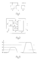
- Each station contains a receiver for those on the bus transmitted signals and usually also a bus driver through which signals from the station in question via the bus to all other stations can be.
- each station for example in station 14 at least one bus driver 21, which is connected to the bus 11, a circuit 22 to process a protocol for the secure transmission of the individual Telegrams and at least one control circuit 23 for processing application-related tasks.
- the bus driver converts the line 24 from the protocol circuit 22 coming serial data in signal level or Wake up level on bus 11 around.
- the bus driver 21 can be connected via lines 26 and 27 in idle mode with very low power consumption, normal operation or to wake up the alarm.
- Signals received from the bus 11 are from the receiver in the bus driver 21 as data via line 25 to the other Processing to the protocol circuit 22, which transfers the data to the Control circuit 23 passes on.
- the protocol circuit 22 also receives data from the control circuit 23 for forwarding to the bus driver 21.
- the bus driver can signal a detected wake-up request via line 28. This will the station is put into an active state, for example parts of the station such as the bus driver or parts of the control circuit are connected to the Supply voltage connected.
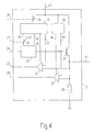
- Fig. 4 shows the structure of the bus driver 21 in principle.
- a voltage converter 31 provides voltages V1 as signal level and V2 from a supplied voltage V7 available as wake-up level for the control circuit 32, which in turn at a logic 1 on line 24 coming from control circuit 23 in Fig. 2, switches the transistor 37 as a voltage follower such that the Set level V1 or V2. Via the control circuit 23 coming line 27, the switch 35 from V1 to V2 and thus from normal operation switched to sending an alarm level.
- transistor 37 remains off and turns on the quiescent level predetermined by resistor 38 occurs on the bus.
- the receiver in the bus driver 21 is essentially controlled by the comparators 33 and 34 formed.
- the voltage converter 31 also provides the Reference voltage V3 for receiving the data by means of comparator 33 and the Supply voltage V5 for supplying the comparator 33 is available. Regardless of whether a station transmits with signal levels or wake-up levels, the data is based on the reception threshold V3 effective for both levels always received correctly and via the line 25 of the protocol circuit 22 in FIG. 2 fed.
- the circuit 39 provides reference voltage V4 and Supply voltage V6 for receiving the wake-up signals by means of comparator 34 Available, which are supplied via line 28 to the control circuit 23 in FIG. 2 will.
- the bus driver can be switched via switch 36 by means of line 26 from the control circuit be put into idle mode by the voltage converter 31 and thus the Voltages V1, V2, V3, V5 and V8 are switched off and only the circuit 39 and so that the comparator 34 remains active by an incoming wake-up level evaluate and be able to output a signal on line 28.
- About the Line 26 can also switch off further circuits of the stations the protocol circuit.
Landscapes
- Engineering & Computer Science (AREA)
- Computer Networks & Wireless Communication (AREA)
- Signal Processing (AREA)
- Small-Scale Networks (AREA)
- Communication Control (AREA)
- Power Sources (AREA)
Applications Claiming Priority (2)
| Application Number | Priority Date | Filing Date | Title |
|---|---|---|---|
| DE19704862A DE19704862A1 (de) | 1997-02-10 | 1997-02-10 | System zum Übertragen von Daten |
| DE19704862 | 1997-02-10 |
Publications (2)
| Publication Number | Publication Date |
|---|---|
| EP0863639A1 true EP0863639A1 (fr) | 1998-09-09 |
| EP0863639B1 EP0863639B1 (fr) | 2005-07-06 |
Family
ID=7819737
Family Applications (1)
| Application Number | Title | Priority Date | Filing Date |
|---|---|---|---|
| EP98200340A Expired - Lifetime EP0863639B1 (fr) | 1997-02-10 | 1998-02-05 | Système pour la transmission de données |
Country Status (4)
| Country | Link |
|---|---|
| US (1) | US6674762B2 (fr) |
| EP (1) | EP0863639B1 (fr) |
| JP (1) | JP4455681B2 (fr) |
| DE (2) | DE19704862A1 (fr) |
Cited By (4)
| Publication number | Priority date | Publication date | Assignee | Title |
|---|---|---|---|---|
| EP1081898A2 (fr) | 1999-09-04 | 2001-03-07 | Adam Opel Ag | Véhicule automobile avec une unité de commande en modes multiples |
| WO2002003618A1 (fr) * | 2000-06-30 | 2002-01-10 | Robert Bosch Gmbh | Procede, appareil et gestionnaire de bus pour le fonctionnement d'un appareil raccorde a un reseau de communication automobile |
| WO2003104037A1 (fr) | 2002-06-10 | 2003-12-18 | Philips Intellectual Property & Standards Gmbh | Procede et systeme pour le passage d'un mode de fonctionnement sous-reseau a un mode de fonctionnement reseau complet |
| DE102005013375A1 (de) * | 2005-03-23 | 2006-09-28 | Bayerische Motoren Werke Ag | Datenbussystem für Kraftfahrzeuge und Verfahren zum Betreiben eines Datenbussystems |
Families Citing this family (10)
| Publication number | Priority date | Publication date | Assignee | Title |
|---|---|---|---|---|
| US6484082B1 (en) * | 2000-05-24 | 2002-11-19 | General Motors Corporation | In-vehicle network management using virtual networks |
| US7170949B2 (en) | 2002-03-14 | 2007-01-30 | Intel Corporation | Methods and apparatus for signaling on a differential link |
| KR100498340B1 (ko) * | 2003-02-04 | 2005-07-01 | 엘지전자 주식회사 | 이동 통신 단말기의 데이터 수신 방법 |
| KR100584446B1 (ko) * | 2004-02-11 | 2006-05-26 | 삼성전자주식회사 | 광대역 무선 접속 통신 시스템에서 단말의 동작 모드 제어방법 |
| US20090213915A1 (en) * | 2004-06-30 | 2009-08-27 | Koninklijke Philips Electronics N.V. | Method for the non-bitrate-dependent encoding of digital signals on a bus system |
| EP2309677B1 (fr) * | 2009-10-06 | 2012-09-05 | Nxp B.V. | Détecteur de réveil d'un émetteur-récepteur de bus |
| DE102015102352A1 (de) | 2015-02-19 | 2016-08-25 | Dr. Ing. H.C. F. Porsche Aktiengesellschaft | Verfahren und Vorrichtung zum Überwachen eines Ruhezustandes bei einem Kraftfahrzeug |
| DE102020110984A1 (de) * | 2020-04-22 | 2021-10-28 | Infineon Technologies Ag | Bus-transceiver |
| DE102020209346A1 (de) * | 2020-07-24 | 2022-01-27 | Robert Bosch Gesellschaft mit beschränkter Haftung | Einrichtungen für eine Teilnehmerstation eines seriellen Bussystems und Verfahren zur Kommunikation in einem seriellen Bussystem |
| CN116632982A (zh) * | 2023-07-19 | 2023-08-22 | 宁德时代新能源科技股份有限公司 | 唤醒电路和电池管理系统 |
Citations (3)
| Publication number | Priority date | Publication date | Assignee | Title |
|---|---|---|---|---|
| US4965550A (en) * | 1989-10-30 | 1990-10-23 | Chrysler Corporation | Automatic wake-up circuit arrangement for a single wire multiplex switch monitoring system |
| JPH0774763A (ja) * | 1993-09-03 | 1995-03-17 | Furukawa Electric Co Ltd:The | 多重伝送システムの動作状態遷移方法 |
| DE19523031A1 (de) * | 1995-06-08 | 1996-12-12 | Philips Patentverwaltung | System zum Übertragen von Daten über einen differentiellen Bus |
Family Cites Families (8)
| Publication number | Priority date | Publication date | Assignee | Title |
|---|---|---|---|---|
| DE3636317A1 (de) * | 1985-10-25 | 1987-04-30 | Yamatake Honeywell Co Ltd | Datenuebertragungssystem mit ueber eine uebertragungsschleife uebermittelten senderechtsanforderungssignalen |
| EP0235648B1 (fr) * | 1986-02-17 | 1990-12-27 | Siemens Aktiengesellschaft | Montage pour la transmission de données en série entre plusieurs terminaux |
| JP2805151B2 (ja) * | 1989-02-15 | 1998-09-30 | 古河電気工業株式会社 | 故障診断装置 |
| JP2752030B2 (ja) * | 1993-04-16 | 1998-05-18 | 沖電気工業株式会社 | ローカルエリアネットワーク回線における信号送受信装置 |
| US5790946A (en) * | 1993-07-15 | 1998-08-04 | Rotzoll; Robert R. | Wake up device for a communications system |
| DE4342036C2 (de) * | 1993-12-09 | 2002-10-24 | Conti Temic Microelectronic | Datenbussystem |
| US5463658A (en) * | 1994-03-23 | 1995-10-31 | Intel Corporation | Low impact collision detection method |
| US5650757A (en) * | 1996-03-27 | 1997-07-22 | Hewlett-Packard Company | Impedance stepping for increasing the operating speed of computer backplane busses |
-
1997
- 1997-02-10 DE DE19704862A patent/DE19704862A1/de not_active Withdrawn
-
1998
- 1998-02-05 DE DE59812904T patent/DE59812904D1/de not_active Expired - Lifetime
- 1998-02-05 EP EP98200340A patent/EP0863639B1/fr not_active Expired - Lifetime
- 1998-02-09 JP JP02719698A patent/JP4455681B2/ja not_active Expired - Fee Related
- 1998-02-09 US US09/020,608 patent/US6674762B2/en not_active Expired - Lifetime
Patent Citations (3)
| Publication number | Priority date | Publication date | Assignee | Title |
|---|---|---|---|---|
| US4965550A (en) * | 1989-10-30 | 1990-10-23 | Chrysler Corporation | Automatic wake-up circuit arrangement for a single wire multiplex switch monitoring system |
| JPH0774763A (ja) * | 1993-09-03 | 1995-03-17 | Furukawa Electric Co Ltd:The | 多重伝送システムの動作状態遷移方法 |
| DE19523031A1 (de) * | 1995-06-08 | 1996-12-12 | Philips Patentverwaltung | System zum Übertragen von Daten über einen differentiellen Bus |
Cited By (12)
| Publication number | Priority date | Publication date | Assignee | Title |
|---|---|---|---|---|
| EP1081898A2 (fr) | 1999-09-04 | 2001-03-07 | Adam Opel Ag | Véhicule automobile avec une unité de commande en modes multiples |
| DE19942368A1 (de) * | 1999-09-04 | 2001-03-08 | Opel Adam Ag | Kraftfahrzeug mit in verschiedenen Modi betreibbaren Steuergeräten |
| EP1081898A3 (fr) * | 1999-09-04 | 2004-04-14 | Adam Opel Ag | Véhicule automobile avec une unité de commande en modes multiples |
| DE19942368B4 (de) * | 1999-09-04 | 2010-04-29 | Adam Opel Ag | Kraftfahrzeug mit in verschiedenen Modi betreibbaren Steuergeräten |
| WO2002003618A1 (fr) * | 2000-06-30 | 2002-01-10 | Robert Bosch Gmbh | Procede, appareil et gestionnaire de bus pour le fonctionnement d'un appareil raccorde a un reseau de communication automobile |
| US7158869B2 (en) | 2000-06-30 | 2007-01-02 | Robert Bosch Gmbh | Method,device and bus manager for operating a device that is connected to a motor vehicle communications network |
| WO2003104037A1 (fr) | 2002-06-10 | 2003-12-18 | Philips Intellectual Property & Standards Gmbh | Procede et systeme pour le passage d'un mode de fonctionnement sous-reseau a un mode de fonctionnement reseau complet |
| WO2003104036A1 (fr) * | 2002-06-10 | 2003-12-18 | Philips Intellectual Property & Standards Gmbh | Procede et systeme pour le passage d'un mode de fonctionnement sous-reseau a un mode de fonctionnement reseau complet |
| CN100414915C (zh) * | 2002-06-10 | 2008-08-27 | Nxp股份有限公司 | 在子网运行和总网运行之间切换的方法和系统 |
| US8566466B2 (en) | 2002-06-10 | 2013-10-22 | Nxp B.V. | Method and system for switching between subnetwork operation and full network operation |
| DE102005013375A1 (de) * | 2005-03-23 | 2006-09-28 | Bayerische Motoren Werke Ag | Datenbussystem für Kraftfahrzeuge und Verfahren zum Betreiben eines Datenbussystems |
| DE102005013375B4 (de) * | 2005-03-23 | 2014-10-30 | Bayerische Motoren Werke Aktiengesellschaft | Datenbussystem für Kraftfahrzeuge und Verfahren zum Betreiben eines Datenbussystems |
Also Published As
| Publication number | Publication date |
|---|---|
| DE19704862A1 (de) | 1998-08-13 |
| US6674762B2 (en) | 2004-01-06 |
| EP0863639B1 (fr) | 2005-07-06 |
| JPH10233793A (ja) | 1998-09-02 |
| DE59812904D1 (de) | 2005-08-11 |
| JP4455681B2 (ja) | 2010-04-21 |
| US20030208700A1 (en) | 2003-11-06 |
Similar Documents
| Publication | Publication Date | Title |
|---|---|---|
| DE3300262C2 (fr) | ||
| EP0863639B1 (fr) | Système pour la transmission de données | |
| DE10145722A1 (de) | Konzept zur sicheren Datenkommunikation zwischen elektronischen Bausteinen | |
| EP0345493A1 (fr) | Dispositif de surveillance, de commande et de régulation d'une installation technique de systèmes d'automation de bâtiments | |
| DE2165667A1 (de) | Zeitmultiplex Übertragungseinrichtung | |
| DE3300260A1 (de) | Schaltungsanordnung zur zuteilung des zugriffs zu einer auf anforderungsbasis gemeinsam benutzten sammelleitung | |
| DE19708979B4 (de) | System zur Datenkommunikation über einen optischen Bus und Verfahren zur Steuerung des Systems | |
| DE10339887B4 (de) | Geräte mit gegenseitiger Aufweckfunktion aus dem Bereitschaftsmodus | |
| DE19750317A1 (de) | Empfangsschaltung für ein CAN-System | |
| DE19629868A1 (de) | Verfahren zur Übertragung binärer Daten und Schnittstellenbausteine zur Durchführung des Verfahrens | |
| DE69524320T2 (de) | Digitale Kommunikationsein- und ausgangsschnittstelle | |
| DE4226704A1 (de) | Verfahren zum Betreiben einer Anlage mit mehreren an ein Bus-System angeschlossenen Komponenten und Schnittstellen-Schaltungsanordnung zur Durchführung des Verfahrens | |
| DE3545293C2 (fr) | ||
| DE19705365A1 (de) | Vorrichtung zur zeitmultiplexen Übertragung von Informationen | |
| DE3687047T2 (de) | Uebertragungsschaltung. | |
| DE102006060081B3 (de) | Kommunikationsvorrichtung zur Kommunikation nach einer Master-Slave-Kommunikationsvorschrift | |
| DE2423195A1 (de) | Wartungsvorrichtung | |
| DE69733510T2 (de) | Datenübertragungssystem zwischen Master und Slave und Slave zur Verwendung desselben | |
| EP0840229B1 (fr) | Dispositif et méthode de sélection de mots d'adresse | |
| EP1408415B1 (fr) | Circuit pour déterminer le contrôleur ayant envoyé un signal de réveil à un bus comportant plusieurs autres contrôleurs | |
| EP0183998A2 (fr) | Reconnaissance de collisions d'informations | |
| DE10306973A1 (de) | Einrichtung zur Datenübertragung zwischen einem ortfesten und mindestens einem mobilen Teilnehmer oder zwischen mobilen Teilnehmern | |
| DE102017113538A1 (de) | Steuereinrichtung für einen Leistungshalbleiterschalter | |
| EP0480331A2 (fr) | Système de traitement de données avec terminaux d'affichage | |
| EP1248987A2 (fr) | Systeme a bus multi-maitre |
Legal Events
| Date | Code | Title | Description |
|---|---|---|---|
| PUAI | Public reference made under article 153(3) epc to a published international application that has entered the european phase |
Free format text: ORIGINAL CODE: 0009012 |
|
| AK | Designated contracting states |
Kind code of ref document: A1 Designated state(s): DE FR GB IT |
|
| AX | Request for extension of the european patent |
Free format text: AL;LT;LV;MK;RO;SI |
|
| 17P | Request for examination filed |
Effective date: 19990309 |
|
| AKX | Designation fees paid |
Free format text: DE FR GB IT |
|
| RBV | Designated contracting states (corrected) |
Designated state(s): DE FR GB IT |
|
| RAP3 | Party data changed (applicant data changed or rights of an application transferred) |
Owner name: KONINKLIJKE PHILIPS ELECTRONICS N.V. Owner name: PHILIPS CORPORATE INTELLECTUAL PROPERTY GMBH |
|
| RAP1 | Party data changed (applicant data changed or rights of an application transferred) |
Owner name: KONINKLIJKE PHILIPS ELECTRONICS N.V. Owner name: PHILIPS CORPORATE INTELLECTUAL PROPERTY GMBH |
|
| RAP1 | Party data changed (applicant data changed or rights of an application transferred) |
Owner name: KONINKLIJKE PHILIPS ELECTRONICS N.V. Owner name: PHILIPS INTELLECTUAL PROPERTY & STANDARDS GMBH |
|
| 17Q | First examination report despatched |
Effective date: 20040212 |
|
| GRAP | Despatch of communication of intention to grant a patent |
Free format text: ORIGINAL CODE: EPIDOSNIGR1 |
|
| GRAS | Grant fee paid |
Free format text: ORIGINAL CODE: EPIDOSNIGR3 |
|
| GRAA | (expected) grant |
Free format text: ORIGINAL CODE: 0009210 |
|
| AK | Designated contracting states |
Kind code of ref document: B1 Designated state(s): DE FR GB IT |
|
| REG | Reference to a national code |
Ref country code: GB Ref legal event code: FG4D Free format text: NOT ENGLISH |
|
| REF | Corresponds to: |
Ref document number: 59812904 Country of ref document: DE Date of ref document: 20050811 Kind code of ref document: P |
|
| GBT | Gb: translation of ep patent filed (gb section 77(6)(a)/1977) |
Effective date: 20050912 |
|
| ET | Fr: translation filed | ||
| PLBE | No opposition filed within time limit |
Free format text: ORIGINAL CODE: 0009261 |
|
| STAA | Information on the status of an ep patent application or granted ep patent |
Free format text: STATUS: NO OPPOSITION FILED WITHIN TIME LIMIT |
|
| 26N | No opposition filed |
Effective date: 20060407 |
|
| REG | Reference to a national code |
Ref country code: GB Ref legal event code: 732E |
|
| REG | Reference to a national code |
Ref country code: FR Ref legal event code: TP |
|
| PG25 | Lapsed in a contracting state [announced via postgrant information from national office to epo] |
Ref country code: IT Free format text: LAPSE BECAUSE OF NON-PAYMENT OF DUE FEES Effective date: 20080205 |
|
| PGFP | Annual fee paid to national office [announced via postgrant information from national office to epo] |
Ref country code: FR Payment date: 20120316 Year of fee payment: 15 |
|
| PGFP | Annual fee paid to national office [announced via postgrant information from national office to epo] |
Ref country code: DE Payment date: 20120123 Year of fee payment: 15 |
|
| PGFP | Annual fee paid to national office [announced via postgrant information from national office to epo] |
Ref country code: IT Payment date: 20120121 Year of fee payment: 15 Ref country code: GB Payment date: 20120131 Year of fee payment: 15 |
|
| GBPC | Gb: european patent ceased through non-payment of renewal fee |
Effective date: 20130205 |
|
| REG | Reference to a national code |
Ref country code: FR Ref legal event code: ST Effective date: 20131031 |
|
| REG | Reference to a national code |
Ref country code: DE Ref legal event code: R119 Ref document number: 59812904 Country of ref document: DE Effective date: 20130903 |
|
| PG25 | Lapsed in a contracting state [announced via postgrant information from national office to epo] |
Ref country code: IT Free format text: LAPSE BECAUSE OF NON-PAYMENT OF DUE FEES Effective date: 20130205 |
|
| PG25 | Lapsed in a contracting state [announced via postgrant information from national office to epo] |
Ref country code: FR Free format text: LAPSE BECAUSE OF NON-PAYMENT OF DUE FEES Effective date: 20130228 Ref country code: DE Free format text: LAPSE BECAUSE OF NON-PAYMENT OF DUE FEES Effective date: 20130903 Ref country code: GB Free format text: LAPSE BECAUSE OF NON-PAYMENT OF DUE FEES Effective date: 20130205 |